manuals.online logo
Brands
  1. Home
  2. •
  3. Brands
  4. •
  5. Hi-Par
  6. •
  7. Control Unit
  8. •
  9. Hi-Par HP600E Control User manual

Hi-Par HP600E Control User manual

Data is based on operation of a standard HPS/MH lamp.
Supply power is based on typical commercial 240V,50/60Hz.
Note: When the controller is connected the CONTROL indicator LED ashes 2 times every 2
seconds - indicating controller is functioning correctly. However, if the Connect Link Cable is
removed during operation the ballast will shut down after 3 minutes. When operating
ballast without a HI-PAR Control Station the CONTROL indicator LED will be o. Turn power
o and on to reset the ballast when either connecting or disconnecting the Control Station.
BOX CONTENT:
1 x 600w Digital Ballast
1 x Power Cord
1 x Connect Link Cable
4 x Rubber Feet
1 x User Manual
1. Digital Ballast
E40 and DE
lamp compatible
5. OUTPUT to
HPS or MH lamp
2. Power Cord
3. Magnet Ring
4. Power Input
8. Connect
Link Cable 7. Dimming Knob
Performance
Model
HP600E
Control
Model
Voltage
(V)
Max Input
Power
(W)
Maximum
Current
(A)
Power
Factor
(COSθ)
Working
Voltage
(V)
Ignitor
Voltage
(kV)
240V 711
THD
<10% 3.0 .99 216-264 4.0
USER MANUAL
HP600E Control for HPS and MH lamps
Installation Directions
6. Rubber Feet
STATUS LED
Output lock down
Output errors
Low input voltage
Over temperature
High input
1 Flash
2 Flash
3 Flash
4 Flash
5 Flash
MIN
MAINS POWER
669
615
456
361
MAX
711
657
498
402
BOOST
100%
75%
60%
MIN
LAMP POWER
639
579
429
339
MAX
681
621
471
381
BOOST
100%
75%
60%
Physical Data
Length (mm)Model Width (mm) High (mm) Colour Material Weight (kgs)
314HP600E Control 112 77 Black Aluminium 3.0
WARNING: This manual contains important safety that should be followed
during the installation and maintenance of the product. Please read this manual
thoroughly before attempting to install or operate this product.
1. Before any assembly or maintenance, make sure the power supply is turned o.
2. To ensure safe system operation, only use certied light shades, cords, and
lamp sockets which match a national or international safety standard.
3. Lamp must be operated a distance away from any ammable substance.
4. Do not cover the digital ballast without proper heat sinking; doing so may aect
the normal case temperature (tc) of the digital ballast. Improper heat dissipation
may shorten ballast life and void the warranty. tc=70oC/158oF.
5. Product is for indoor/enclosed use only; it must be protected from water/liquids.
6. Ensure proper mounting and installation of the digital ballast; it must be securely
fastened to a xed substrate to protect it from detachment, impact and excessive
vibrations. If not secured, damage to the unit or persons may result.
7. Please ensure the input power matches with the specications of the digital
Ballast. If you are not clear about the electrical source, please contact your power
utility company, an electrician or your local distributor.
8. Install the power cord so it can not be pinched, stepped on or tripped over;
secure cord and digital ballast properly to avoid lighting interruptions/hazards.
9. If the power cord needs to be extended, please make sure it meets the standard
electrical safety requirement; the wire diameter should be at least 1.5mm² or 16AWG. Not
following electrical code may result in re or other accidents.
10. To avoid the risk of shock or re, and as to not void the Warranty, do
not open or disassemble the digital ballast.
11. If you have any questions on the installation of the digital ballast, or should you
experience any trouble please contact your local authorised HI-PAR dealer.
Connecting the Ballast
- Please refer to the included wiring diagram for proper wiring connection.
- Only use the provided cables to connect the ballast to the power supply/socket.
- Insert recommended HPS/MH lamp into lamp socket.
- Ensure lamp type is correct orientation.
- Do not use an external ignitor.
- Lamps with auto-ignitor will not work with the digital ballast.
- Connect the ballast into the Hi-PAR Control Station.
Ignitor Safe Protection
The Digital Ballast will ignite automatically. During this period, the ballast can protect
itself without manual intervention. If HPS lamp does not work after 5 minutes (For MH, at
most 15 min), please check the connection or change the lamp.
User Guide
This product must be equipped with the right High Pressure Sodium
lamp (HPS) or Metal Halide lamp (MH) to get the highest eciency,
safety, and luminance output from the lamp.
Connecting the Ballast to the HI-PAR‘Control Station’ (controller - sold separately)
- Control Station communicates with ballast via TRS (Stereo) cable
- Multiple ballasts can be installed in‘daisy-chain’arrangement
- Up to 200 Ballasts per zone, two zones per Control Station
- Control Station and Thermo Sensors regulate timing and dimming control
CONTROL STATION Compatible - Plug and Play Linkable 400 Fixture - 200 Ballast on each channel
ZONE A
THERMO SENSOR
POWER
THERMO SENSOR
UP TO
200
BALLASTS
UP TO
200
BALLASTS ZONE B
www.hi-par-horticulture.comwww.hi-par-horticulture.com
Other Hi-Par Control Unit manuals

Hi-Par HP1000E Control User manual

Hi-Par

Hi-Par HP1000E Control User manual

Hi-Par HP315E Control User manual

Hi-Par

Hi-Par HP315E Control User manual

Popular Control Unit manuals by other brands

Comelit 20004605 Technical manual

Comelit

Comelit 20004605 Technical manual

Datasensor BWS-T2 Series instruction manual

Datasensor

Datasensor BWS-T2 Series instruction manual

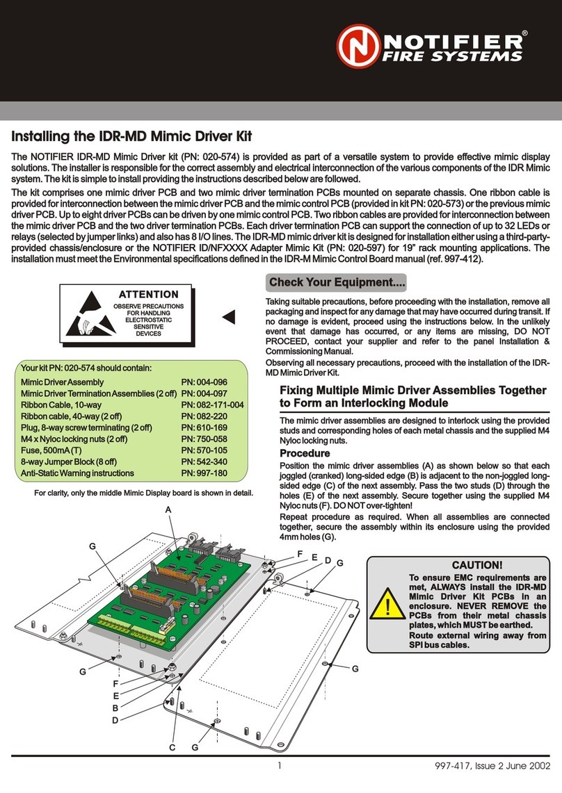
Notifier IDR-MD quick start guide

Notifier

Notifier IDR-MD quick start guide

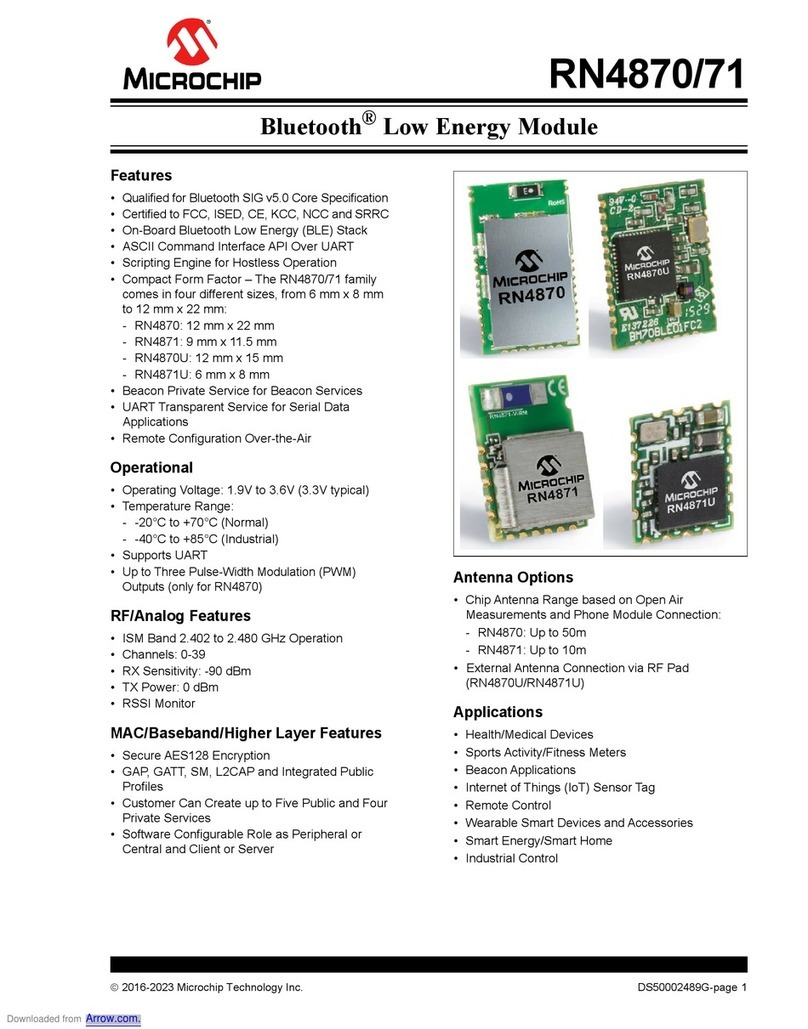
Microchip Technology RN4870 manual

Microchip Technology

Microchip Technology RN4870 manual

GatesAir Intraplex DS-64NC Installation and operation manual

GatesAir

GatesAir Intraplex DS-64NC Installation and operation manual

ICP DAS USA tPET-P6 quick start guide

ICP DAS USA

ICP DAS USA tPET-P6 quick start guide

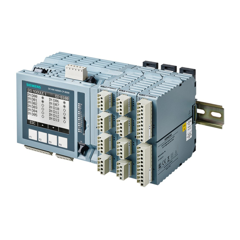
Siemens SICAM A8000 Series quick start guide

Siemens

Siemens SICAM A8000 Series quick start guide

EOS Farblichtmodul Assembly instruction

EOS

EOS Farblichtmodul Assembly instruction

GRASS VALLEY KAMELEON Series instruction manual

GRASS VALLEY

GRASS VALLEY KAMELEON Series instruction manual

Texas Instruments DRV8601 user guide

Texas Instruments

Texas Instruments DRV8601 user guide

HP HPE FlexNetwork 7500 quick start guide

HP

HP HPE FlexNetwork 7500 quick start guide

Rockwell Automation Allen-Bradley FLEX Ex 1797-IRT8 user manual

Rockwell Automation

Rockwell Automation Allen-Bradley FLEX Ex 1797-IRT8 user manual

Ebyte E104-BT02 user manual

Ebyte

Ebyte E104-BT02 user manual

MADDALENA Arrow WAN 2 Instructions for installation, use and maintenance

MADDALENA

MADDALENA Arrow WAN 2 Instructions for installation, use and maintenance

Siemens SIRIUS 3SF5811 A Series Original operating instructions

Siemens

Siemens SIRIUS 3SF5811 A Series Original operating instructions

Locomarine NMEA0183 TO ETHERNET CONVERTER installation manual

Locomarine

Locomarine NMEA0183 TO ETHERNET CONVERTER installation manual

Denon RC-7000CI - Remote Control - Infrared/radio owner's manual

Denon

Denon RC-7000CI - Remote Control - Infrared/radio owner's manual

Harvia C150 manual

Harvia

Harvia C150 manual

manuals.online logo
manuals.online logoBrands
  • About & Mission
  • Contact us
  • Privacy Policy
  • Terms and Conditions

Copyright 2025 Manuals.Online. All Rights Reserved.