manuals.online logo
Brands
  1. Home
  2. •
  3. Brands
  4. •
  5. Notifier
  6. •
  7. Control Unit
  8. •
  9. Notifier IDR-MD User manual

Notifier IDR-MD User manual

997-417, Issue 2 June 2002
EE
FFDDGG
GG
GG
GG
CCGG
BB
FF
DD
EE
AA
Check Your Equipment....Check Your Equipment....
The NOTIFIER IDR-MD Mimic Driver kit (PN: 020-574) is provided as part of a versatile system to provide effective mimic display
solutions. The installer is responsible for the correct assembly and electrical interconnection of the various components of the IDR Mimic
system. The kit is simple to install providing the instructions described below are followed.
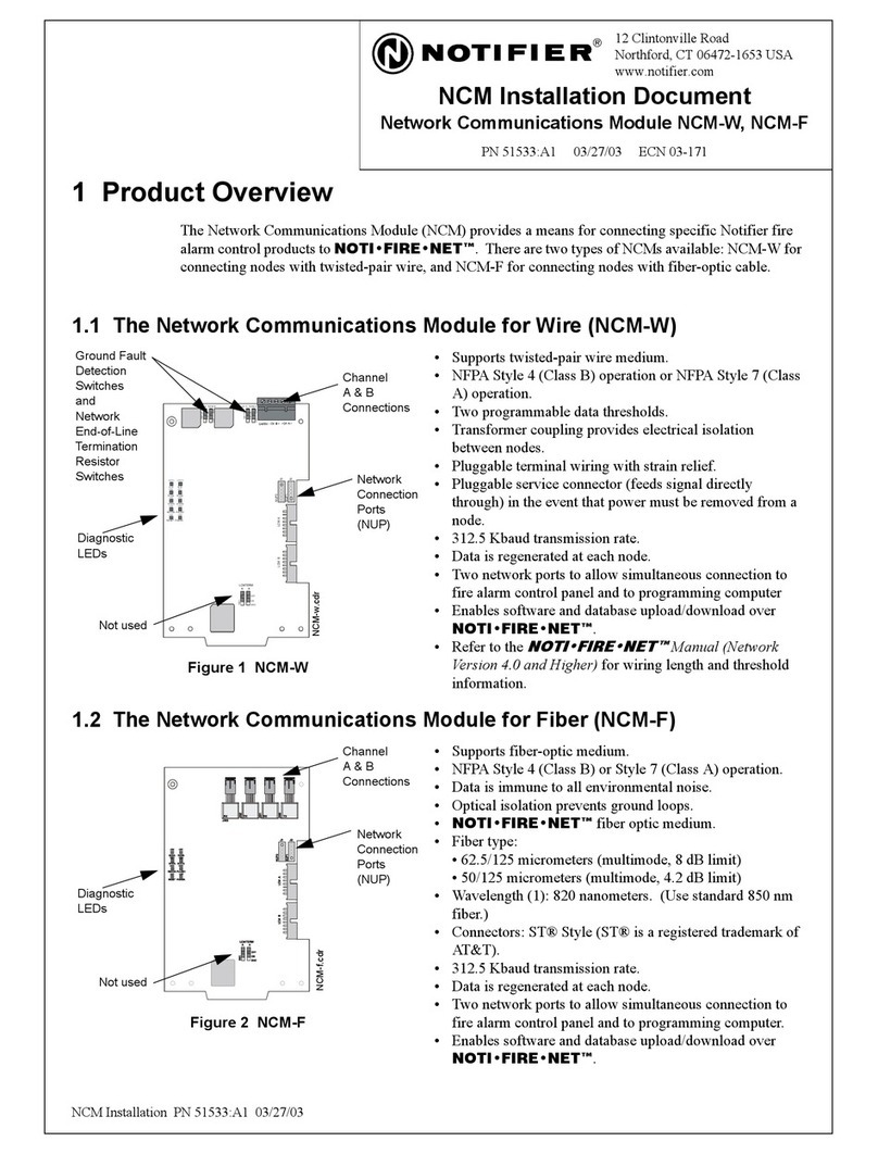
The kit comprises one mimic driver PCB and two mimic driver termination PCBs mounted on separate chassis. One ribbon cable is
provided for interconnection between the mimic driver PCB and the mimic control PCB (provided in kit PN: 020-573) or the previous mimic
driver PCB. Up to eight driver PCBs can be driven by one mimic control PCB. Two ribbon cables are provided for interconnection between
the mimic driver PCB and the two driver termination PCBs. Each driver termination PCB can support the connection of up to 32 LEDs or
relays (selected by jumper links) and also has 8 I/O lines. The IDR-MD mimic driver kit is designed for installation either using a third-party-
provided chassis/enclosure or the NOTIFIER ID/NFXXXX Adapter Mimic Kit (PN: 020-597) for 19” rack mounting applications. The
installation must meet the Environmental specifications defined in the IDR-M Mimic Control Board manual (ref. 997-412).
Taking suitable precautions, before proceeding with the installation, remove all
packaging and inspect for any damage that may have occurred during transit. If
no damage is evident, proceed using the instructions below. In the unlikely
event that damage has occurred, or any items are missing, DO NOT
PROCEED, contact your supplier and refer to the panel Installation &
Commissioning Manual.
Observing all necessary precautions, proceed with the installation of the IDR-
MD Mimic Driver Kit.
OBSERVE PRECAUTIONS
FOR HANDLING
ELECTROSTATIC
SENSITIVE
DEVICES
OBSERVE PRECAUTIONS
FOR HANDLING
ELECTROSTATIC
SENSITIVE
DEVICES
ATTENTIONATTENTION
Your kit PN: 020-574 should contain:
Mimic Driver Assembly PN: 004-096
Mimic Driver TerminationAssemblies (2 off) PN: 004-097
Ribbon Cable, 10-way PN: 082-171-004
Ribbon cable, 40-way (2 off) PN: 082-220
Plug, 8-way screw terminating (2 off) PN: 610-169
M4 x Nyloc locking nuts (2 off) PN: 750-058
Fuse, 500mA (T) PN: 570-105
8-way Jumper Block (8 off) PN: 542-340
Anti-Static Warning instructions PN: 997-180
The mimic driver assemblies are designed to interlock using the provided
studs and corresponding holes of each metal chassis and the supplied M4
Nyloc locking nuts.
Procedure
Position the mimic driver assemblies (A) as shown below so that each
joggled (cranked) long-sided edge (B) is adjacent to the non-joggled long-
sided edge (C) of the next assembly. Pass the two studs (D) through the
holes (E) of the next assembly. Secure together using the supplied M4
Nyloc nuts (F). DO NOT over-tighten!
Repeat procedure as required. When all assemblies are connected
together, secure the assembly within its enclosure using the provided
4mm holes (G).
The mimic driver assemblies are designed to interlock using the provided
studs and corresponding holes of each metal chassis and the supplied M4
Nyloc locking nuts.
Position the mimic driver assemblies (A) as shown below so that each
joggled (cranked) long-sided edge (B) is adjacent to the non-joggled long-
sided edge (C) of the next assembly. Pass the two studs (D) through the
holes (E) of the next assembly. Secure together using the supplied M4
Nyloc nuts (F). DO NOT over-tighten!
Repeat procedure as required. When all assemblies are connected
together, secure the assembly within its enclosure using the provided
4mm holes (G).
Procedure
Fixing Multiple Mimic Driver Assemblies Together
to Form an Interlocking Module
Fixing Multiple Mimic Driver Assemblies Together
to Form an Interlocking Module
For clarity, only the middle Mimic Display board is shown in detail.For clarity, only the middle Mimic Display board is shown in detail.
!!
CAUTION!
To ensure EMC requirements are
met, ALWAYS install the IDR-MD
Mimic Driver Kit PCBs in an
enclosure. NEVER REMOVE the
PCBs from their metal chassis
plates, which MUST be earthed.
Route external wiring away from
SPI bus cables.
CAUTION!
To ensure EMC requirements are
met, ALWAYS install the IDR-MD
Mimic Driver Kit PCBs in an
enclosure. NEVER REMOVE the
PCBs from their metal chassis
plates, which MUST be earthed.
Route external wiring away from
SPI bus cables.
1
Installing the IDR-MD Mimic Driver KitInstalling the IDR-MD Mimic Driver Kit

997-417, Issue 2 June 2002
Jumper LinksJumper Links
The 64 output channels are arranged in two banks of 32. Each bank is
arranged in four groups of 8 outputs. Each group is provided with a
jumper link which configures the group to drive either LEDs or relays:
JUMPER LINK FITTED = GROUP DRIVES RELAYS
JUMPER LINK NOT FITTED = GROUP DRIVES LEDs
The groups can be configured independently, i.e. within a bank some
groups may drive relays and others may drive LEDs.
CAUTION:
Ensure that jumper links are configured correctly. If an LED is
connected to an output for which the link is fitted, the LED will
have a short life expectancy. Conversely, if a relay is connected
to an output for which the link is not fitted, the relay will not
operate.
The 64 output channels are arranged in two banks of 32. Each bank is
arranged in four groups of 8 outputs. Each group is provided with a
jumper link which configures the group to drive either LEDs or relays:
JUMPER LINK FITTED = GROUP DRIVES RELAYS
JUMPER LINK NOT FITTED = GROUP DRIVES LEDs
The groups can be configured independently, i.e. within a bank some
groups may drive relays and others may drive LEDs.
CAUTION:
If an LED is
connected to an output for which the link is fitted, the LED will
have a short life expectancy. Conversely, if a relay is connected
to an output for which the link is not fitted, the relay will not
operate.
Ensure that jumper links are configured correctly.
Procedure for Fitting a Mimic Driver
Assembly (typical)
Procedure for Fitting a Mimic Driver
Assembly (typical)
Procedure for Fitting a Mimic Driver
Termination Assembly (typical)
Procedure for Fitting a Mimic Driver
Termination Assembly (typical)
Proceed as follows:
1Find a suitable location to install the mimic driver PCB assembly
(H), such as a third-party-supplied enclosure. Four fixing holes (I)
are provided. Mark and drill the surface where the assembly is to
be mounted to take suitable 4mm-sized screws (not supplied).
2Fit the assembly and secure with the 4mm screws. The assembly
can be mounted vertically or horizontally.
3Refer to the section at the bottom of this page for all required
cable and wiring connections.
Proceed as follows:
Find a suitable location to install the mimic driver PCB assembly
(H), such as a third-party-supplied enclosure. Four fixing holes (I)
are provided. Mark and drill the surface where the assembly is to
be mounted to take suitable 4mm-sized screws (not supplied).
Fit the assembly and secure with the 4mm screws. The assembly
can be mounted vertically or horizontally.
Refer to the section at the bottom of this page for all required
cable and wiring connections.
1
2
3
Proceed as follows:
1Find a suitable location to install the mimic driver termination PCB
assembly (J). To keep the LED wiring as short as possible, locate
the mimic driver termination board(s) close to the LEDs. An
option of four ‘flat-mounting’ holes (K) and/or two ‘edge-on-
mounting’ holes (L) are provided for fitting convenience. Mark
and drill the surface where the assembly is to be mounted to take
suitable 4mm-sized screws (not supplied).
2Fit the assembly and secure with the 4mm screws. The assembly
can be mounted vertically or horizontally.
3Refer to the next section for wiring and LED connections.
Proceed as follows:
Find a suitable location to install the mimic driver termination PCB
assembly (J). To keep the LED wiring as short as possible, locate
the mimic driver termination board(s) close to the LEDs. An
option of four ‘flat-mounting’ holes (K) and/or two ‘edge-on-
mounting’ holes (L) are provided for fitting convenience. Mark
and drill the surface where the assembly is to be mounted to take
suitable 4mm-sized screws (not supplied).
Fit the assembly and secure with the 4mm screws. The assembly
can be mounted vertically or horizontally.
Refer to the next section for wiring and LED connections.
1
2
3
HH
II
MM
II
II
II
JJ
K (x4)K (x4)
L (x2)L (x2)
2
Installing the IDR-MD Mimic Driver Kit (Continued)
MIMIC DRIVER PCBMIMIC DRIVER PCB
124-320124-320
ININ
OUTOUT
JP5JP5
BANK 1
OUTPUTS
1-8
BANK 1
OUTPUTS
1-8
Mimic Driver BoardMimic Driver Board
JP8JP8
JP1JP1
JP4JP4
JP6JP6
JP7JP7
JP2JP2
JP3JP3
BANK 1
OUTPUTS
9-16
BANK 1
OUTPUTS
9-16
BANK 1
OUTPUTS
17-24
BANK 1
OUTPUTS
17-24
BANK 1
OUTPUTS
25-32
BANK 1
OUTPUTS
25-32
BANK 2
OUTPUTS
1-8
BANK 2
OUTPUTS
1-8
BANK 2
OUTPUTS
9-16
BANK 2
OUTPUTS
9-16
BANK 2
OUTPUTS
17-24
BANK 2
OUTPUTS
17-24
BANK 2
OUTPUTS
25-32
BANK 2
OUTPUTS
25-32
!!
997-417, Issue 2 June 2002
3
Installing the IDR-MD Mimic Driver Kit (Continued)
Cabling and Wiring ConnectionsCabling and Wiring Connections
Up to eight mimic driver boards can be driven by one control board.
Connection between each ‘daisy-chained’ mimic driver board, and
between the control board and the first mimic driver, is via a Serial to
Parallel Interface (SPI) bus. A 10-way ribbon cable is supplied for the
interconnection (using the connector marked IN) of:
i) The first mimic driver board and the control board (ZE), or
ii) The mimic driver board and the previous ‘daisy-chained’
mimic driver board connector (marked OUT).
Two 40-way ribbon cables are supplied for interconnection between
the mimic driver board and two mimic termination boards, using
connectors J4 (first group of 32 zones) and J3 (second group of 32).
Note: If the supplied 40-way ribbon cables are not long enough for
your site application, use a suitable alternative, up to a
maximum length of 10m. The system uses standard
specification ribbon cable: 28AWG, 0.050” pitch. Connectors
used are 40-way, bump-polarised, female plugs.
For the discrete wiring between the Mimic Termination board and the
LEDs (maximum of 10m): 7/0.2 wire is recommended.
Each mimic driver board chassis plate is provided with an M4 earth
stud (M), one of which MUST be connected to earth - earthing of the
other units is provided through the interlocking-chassis arrangement.
A simple schematic diagram showing all required power and signal
connections is shown at left. For more details, refer to the IDR-M
Mimic Installation and Commissioning Manual (ref. 997-412).
Up to eight mimic driver boards can be driven by one control board.
Connection between each ‘daisy-chained’ mimic driver board, and
between the control board and the first mimic driver, is via a Serial to
Parallel Interface (SPI) bus. A 10-way ribbon cable is supplied for the
interconnection (using the connector marked IN) of:
i) The first mimic driver board and the control board (ZE), or
ii) The mimic driver board and the previous ‘daisy-chained’
mimic driver board connector (marked OUT).
Two 40-way ribbon cables are supplied for interconnection between
the mimic driver board and two mimic termination boards, using
connectors J4 (first group of 32 zones) and J3 (second group of 32).
If the supplied 40-way ribbon cables are not long enough for
your site application, use a suitable alternative, up to a
maximum length of 10m. The system uses standard
specification ribbon cable: 28AWG, 0.050” pitch. Connectors
used are 40-way, bump-polarised, female plugs.
For the discrete wiring between the Mimic Termination board and the
LEDs (maximum of 10m): 7/0.2 wire is recommended.
Each mimic driver board chassis plate is provided with an M4 earth
stud (M), one of which MUST be connected to earth - earthing of the
other units is provided through the interlocking-chassis arrangement.
A simple schematic diagram showing all required power and signal
connections is shown at left. For more details, refer to the IDR-M
Mimic Installation and Commissioning Manual (ref. 997-412).
Note:
MIMIC DRIVER PCBMIMIC DRIVER PCB
124-320124-320
ININ
OUTOUT
28V/0V to next
Mimic Driver/next station
28V/0V to next
Mimic Driver/next station
MIMIC TERMINATION PCB
124-321
1111
3232
J5J5
3232
Typical 32
positions
(10m max.)
Typical 32
positions
(10m max.)
BANK 1BANK 1
Typical 32
positions
(10m max.)
Typical 32
positions
(10m max.)
MIMIC TERMINATION PCB
124-321
11
11
3232
3232
Pins 1-4 (28V)Pins 1-4 (28V)
Pins 5-8 (0V)Pins 5-8 (0V)
11
To next Mimic DriverTo next Mimic Driver
To last Mimic DriverTo last Mimic Driver
MIMIC DRIVER PCB
ININ J5J5
J3J3
JP5JP5
J4J4
28V/0V28V/0V
SPI BUSSPI BUS
CONTROL PCB
124-318
CONTROL PCB
124-318
JP5
JP6
JP1 JP3
JP2 JP4
TERM OFF
TERM ON
TERMINATION
PCB 124-318
TERMINATION
PCB 124-318
ZEZE
Mimic Control BoardMimic Control Board
Mimic Driver BoardMimic Driver Board
40-way ribbon cable40-way ribbon cable
Mimic Termination
boards
Mimic Termination
boards
JP8JP8
JP1JP1
JP4JP4
BANK 2BANK 2
To Drive LEDs...To Drive LEDs...
There are restrictions on the types of
LED that can be driven by the IDR-M
Mimic. The IDR-M Mimic Installation
and Commissioning Manual (ref. 997-
412) defines the requirements.
There are restrictions on the types of
LED that can be driven by the IDR-M
Mimic. The IDR-M Mimic Installation
and Commissioning Manual (ref. 997-
412) defines the requirements.
!!
Continued overleaf.....Continued overleaf.....
997-417, Issue 2 June 2002
Installing the IDR-MD Mimic Driver Kit (Continued)
4
Additional I/O relay connections are provided at J6 on the Mimic
Driver Board; these are shown in the simple schematic diagram at left.
Additional I/O relay connections are provided at J6 on the Mimic
Driver Board; these are shown in the simple schematic diagram at left.
Mimic Driver BoardMimic Driver Board
ININ
OUTOUT
JP5
JP6
JP1 JP3
JP2 JP4
TERM OFF
TERM ON
Mimic Control BoardMimic Control Board
++
--
++
--
A,BA,B
++
--
Mimic adjacent to PanelMimic adjacent to Panel
Aux
Supply
Aux
Supply
Fire
Control
Panel
Fire
Control
Panel
--++A,BA,B RS485RS485
++
--
++
--
++
--
UP TO 8 RELAYS
DRIVEN BY HIGH
CURRENT I/O
UP TO 8 RELAYS
DRIVEN BY HIGH
CURRENT I/O
J6J6
Mimic Driver BoardMimic Driver Board
ININ
OUTOUT
SPI
BUS
SPI
BUS
40-way ribbon cable40-way ribbon cable
113232
Mimic
Termination
board
Mimic
Termination
board
++
--
++
--
JP5
JP6
JP1 JP3
JP2 JP4
TERM OFF
TERM ON
Mimic Control BoardMimic Control Board
++
--
++
--
A,BA,B
++
--
External PSU
(not supplied)
External PSU
(not supplied)
--
++++
--
++
--
++
--
++
--
TYPICAL RELAYSTYPICAL RELAYS
APPROPRIATE
CUSTOMER-SUPPLIED
FUSE
APPROPRIATE
CUSTOMER-SUPPLIED
FUSE
Mimic remote from PanelMimic remote from Panel
Fire
Control
Panel
Fire
Control
Panel
A,BA,B RS485RS485
SPI
BUS
SPI
BUS
40-way ribbon cable40-way ribbon cable
113232
Mimic
Termination
board
Mimic
Termination
board
++
--
++
--
Mimic Driver BoardMimic Driver Board
ININ
OUTOUT
JP5
JP6
JP1 JP3
JP2 JP4
TERM OFF
TERM ON
Mimic Control BoardMimic Control Board
++
--
++
--
A,BA,B
++
--
TYPICAL RELAYS
(E.G. DIN-MOUNT)
TYPICAL RELAYS
(E.G. DIN-MOUNT)
MAXIMUM NUMBER OF RELAYS IS LIMITED BY THE SUPPLY FROM THE PANELMAXIMUM NUMBER OF RELAYS IS LIMITED BY THE SUPPLY FROM THE PANEL
Mimic adjacent to PanelMimic adjacent to Panel
Aux
Supply
Aux
Supply
Fire
Control
Panel
Fire
Control
Panel
--++A,BA,B RS485RS485
++
--
++
--
++
--
++
--
MAXIMUM
SUPPLY
CURRENT
LIMITED
BY PANEL
MAXIMUM
SUPPLY
CURRENT
LIMITED
BY PANEL
Note: To reduce EMI and prevent damage to the drive circuit, diodes
should be connected across each relay coil as illustrated.
The method of ‘daisy-chaining’ Mimic Driver Boards, and of earthing
them, is identical to that described above for LED connections.
Simple schematic diagrams showing all required power and signal
connections are shown at left. These examples cover the possibilities
that the Mimic is located adjacent to the panel and that it is located
remote from the panel. Both examples show only one Mimic Driver
Board and one Termination board for simplicity.
Further details are given in the IDR-M Mimic Installation and
Commissioning Manual (ref. 997-412).
The discrete wiring between the Mimic Termination board and the
relays must be suitable for the purpose.
To Drive Relays...To Drive Relays...
There are restrictions on the types of
relay that can be driven by the IDR-M
Mimic. The IDR-M Mimic Installation
and Commissioning Manual (ref. 997-
412) defines the requirements and
provides recommendations.
There are restrictions on the types of
relay that can be driven by the IDR-M
Mimic. The IDR-M Mimic Installation
and Commissioning Manual (ref. 997-
412) defines the requirements and
provides recommendations.
!!

This manual suits for next models

1

Other Notifier Control Unit manuals

Notifier FMM-1 FlashScan User manual

Notifier

Notifier FMM-1 FlashScan User manual

Notifier 020-553 Instruction Manual

Notifier

Notifier 020-553 Instruction Manual

Notifier FZM-1 User manual

Notifier

Notifier FZM-1 User manual

Notifier NCM-W Operator's manual

Notifier

Notifier NCM-W Operator's manual

Notifier TM-4 Technical manual

Notifier

Notifier TM-4 Technical manual

Notifier FDM-1 User manual

Notifier

Notifier FDM-1 User manual

Notifier XP6-R User manual

Notifier

Notifier XP6-R User manual

Notifier FDM-1 User manual

Notifier

Notifier FDM-1 User manual

Notifier XP10-M User manual

Notifier

Notifier XP10-M User manual

Notifier NAM-232 User manual

Notifier

Notifier NAM-232 User manual

Notifier XP6-MA User manual

Notifier

Notifier XP6-MA User manual

Notifier LDM-32 Assembly instructions

Notifier

Notifier LDM-32 Assembly instructions

Popular Control Unit manuals by other brands

Pro-face GP4000 SERIES Replacement  guidebook

Pro-face

Pro-face GP4000 SERIES Replacement guidebook

System air Topvex Series installation manual

System air

System air Topvex Series installation manual

Texas Instruments OPT8241-CDK-EVM quick start guide

Texas Instruments

Texas Instruments OPT8241-CDK-EVM quick start guide

Avitech Sequoia 2H2U user manual

Avitech

Avitech Sequoia 2H2U user manual

Telit Wireless Solutions GE866-QUAD Hardware user's guide

Telit Wireless Solutions

Telit Wireless Solutions GE866-QUAD Hardware user's guide

Honeywell 7800 SERIES installation instructions

Honeywell

Honeywell 7800 SERIES installation instructions

Hawle HAWIDO 1402 manual

Hawle

Hawle HAWIDO 1402 manual

SMC Networks VQZ 1000 Installation and maintenance manual

SMC Networks

SMC Networks VQZ 1000 Installation and maintenance manual

HAUTAU LSF 24 operating instructions

HAUTAU

HAUTAU LSF 24 operating instructions

Dynamic Engineering PMC-BiSerial-III HW2 user manual

Dynamic Engineering

Dynamic Engineering PMC-BiSerial-III HW2 user manual

AzureWave AW-NM230NF-H user guide

AzureWave

AzureWave AW-NM230NF-H user guide

Flame DUALKEY EURO MODUL manual

Flame

Flame DUALKEY EURO MODUL manual

ABB 88TK50-E/R1210 Module and Application Description

ABB

ABB 88TK50-E/R1210 Module and Application Description

AMX DG DVI MTP quick start guide

AMX

AMX DG DVI MTP quick start guide

Viessmann SDIO Installation and service instructions for contractors

Viessmann

Viessmann SDIO Installation and service instructions for contractors

StrongLink SL030 user manual

StrongLink

StrongLink SL030 user manual

Beckhoff KS2502 Documentation

Beckhoff

Beckhoff KS2502 Documentation

GMV VC 3006 Instruction

GMV

GMV VC 3006 Instruction

manuals.online logo
manuals.online logoBrands
  • About & Mission
  • Contact us
  • Privacy Policy
  • Terms and Conditions

Copyright 2025 Manuals.Online. All Rights Reserved.