Hidral PH-300 User manual

ASSEMBLY INSTRUCTIONS
IM-560en
Vers. 05
22/09/2021
PH-300
VERTICAL LIFTING PLATFORM
ORIGINAL INSTRUCTIONS


ASSEMBLY INSTRUCTIONS
PH-300 VERTICAL LIFTING PLATFORM
IM-560en
Vers. 05
Page 1
Contents
1. Tools and equipment............................................................................................................... Page 2
2. Shaft check............................................................................................................................. Page 3
3. Guide assembly...................................................................................................................... Page 12
4. Assembly of the machine cabinet ........................................................................................... Page 15
5. Hydraulic installation............................................................................................................... Page 16
6. Electrical installation ............................................................................................................... Page 17
6.1. Guide electrical installation........................................................................................ Page 17
6.2. Machine cabinet electric installation.......................................................................... Page 17
7. Vehicle installation .................................................................................................................. Page 18
8. Landing push button panels.................................................................................................... Page 24
9. Upper landing door assembly................................................................................................. Page 26
10. Protective bellows (optional)................................................................................................. Page 35
11. Electrical adjustment............................................................................................................. Page 36
11.1. Adjustment of the circuit breaker ............................................................................. Page 36
11.2. Adjustment of the stop nal limit switches ............................................................... Page 36
11.3. Adjustment of the opening angle of the automatic door........................................... Page 37
12. Hydraulic adjustment ........................................................................................................... Page 38
12.1. Description of the group .......................................................................................... Page 38
12.2. Hydraulic diagram.................................................................................................... Page 38
12.3. Adjustment of the descent speed ............................................................................ Page 39
13. Adjustment of the overload detection system ....................................................................... Page 39
14. Final tests ............................................................................................................................. Page 40

IM-560en
Vers. 05
Page 2
ASSEMBLY INSTRUCTIONS
VERTICAL LIFTING PLATFORM PH-300
1. Tools and equipment
●Safety goggles
●Gloves
●Safety boots
●Drill with several bore bits for concrete Ø6, Ø10 and Ø16
●Manual resin aplicator HILTI HDM330 for the supplied anchorages
●Spirit level
●Bob plumb
● Complete at spanner or star spanner set
●Torque wrench for 5 Nm
●Star screwdriver
●Slot head screwdriver
●Funnel
●Ruler with a 1.5 m aproximate length
Personal protection
Tools and equipment

ASSEMBLY INSTRUCTIONS
PH-300 VERTICAL LIFTING PLATFORM
IM-560en
Vers. 05
Page 3
2. Shaft check
1 Install suitable protections to prevent risks of falling during assembly.
2 Check that the supplied anchorages are appropriate for the type of wall the guide
shall be xed upon. The chemical anchorages are appropriate for walls made of
structural concrete, solid bricks or hollow brick.
3 Verify the characteristics of the wall to which the guide shall be xed. The guide is
designed to be xed to the oor, to the slab of the upper landing level and on the
upper end of the guide. In case a resistant enough support is not available for the
xation on the upper end of the guide the two upper xations may be moved to the
central xation plate to the slab. The reaction forces of the guide assembly on the
oor and xation wall are indicated in the following drawing.
With xation on the upper
end of the guide
Only with xation to the slab
of the upper landing level
2.5 kN
2 kN
2 kN
0.6 kN
2 kN
0.6 kN
2 kN
R 1100
2.5 kN
2 kN
2 kN
20 kN
20 kN
R 1100
20 kN
20 kN
IM-560en
Vers. 05
Page 4
ASSEMBLY INSTRUCTIONS
VERTICAL LIFTING PLATFORM PH-300
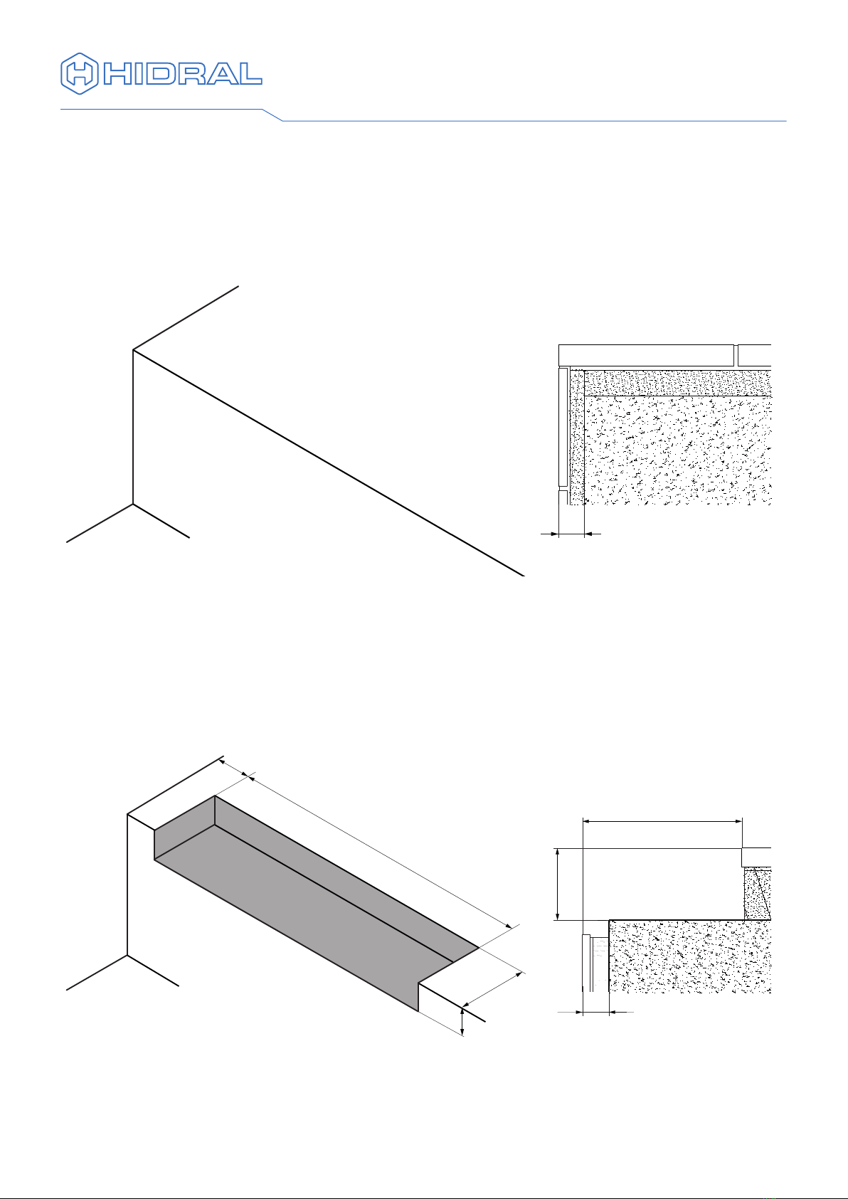
4 Check that the following dimensions are within the specied limits. Should this not
be case, get in touch with our aftersales department.
- R Platform travel. Permissible deviation of ± 50 mm
- E0 Minimum space for access on lower level: ≥2040
Upper
level
Lower
level
R
E0
- E1 Minimum space on upper level with 180º access: ≥1200
Upper levelLower level
E1
d
- E1 Minimum space on upper level with 90º access: ≥1200
Upper level
Lower level
E1
d

ASSEMBLY INSTRUCTIONS
PH-300 VERTICAL LIFTING PLATFORM
IM-560en
Vers. 05
Page 5
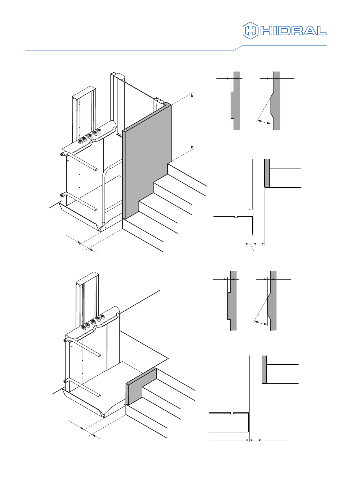
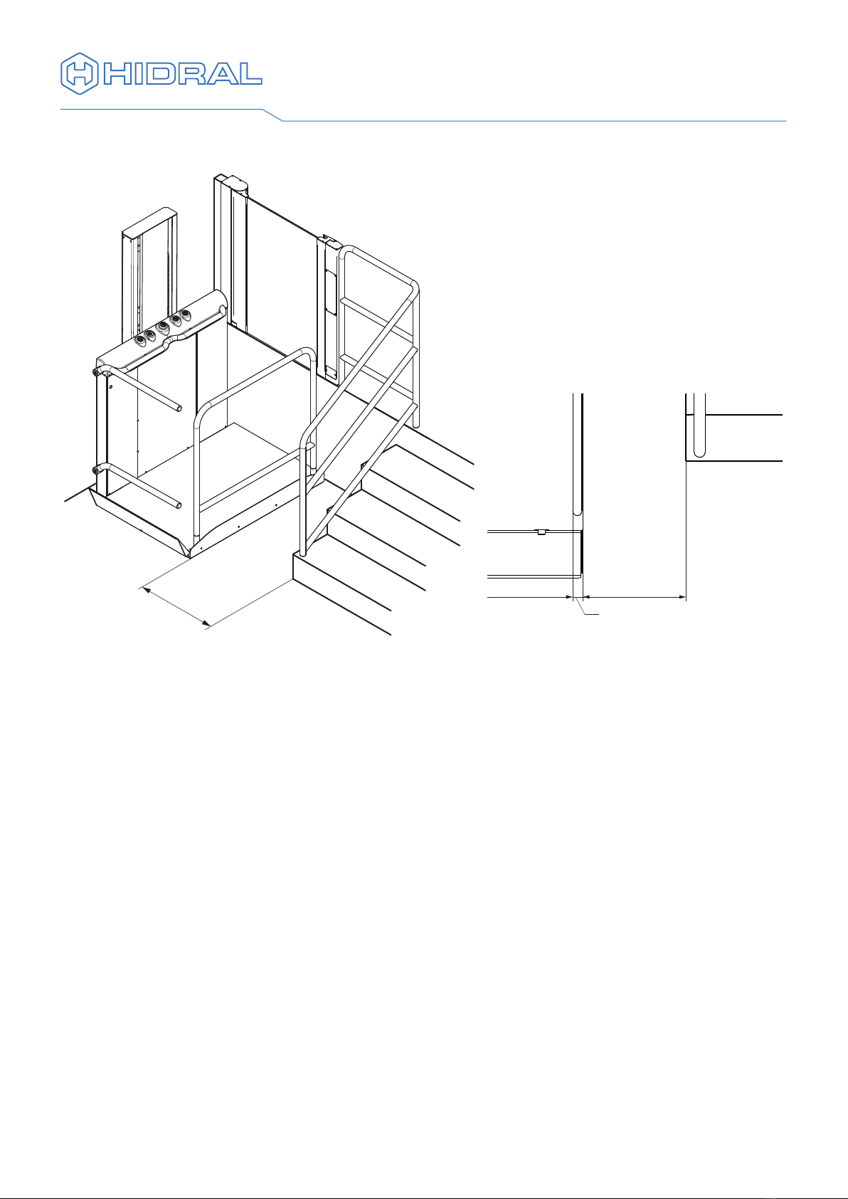
5 Check adjacent surface requirements:
- Upper access side. Vertical, continuous, solid and without projections; throughout
the dimension of the platform
- Guide side. Vertical, continuous, solid and without projections
- Side without access. According to the value of the travel (R) and the distance to the
platform (d):
R≤500 R>500 Surface
- d=20 Vertical, continuous, solid and without projections;
throughout the dimension of the platform
20≤d<120 80≤d<120 Vertical, continuous, solid and without projections
120≤d<400 Vertical, continuous and solid
d≥400 No specic requirements
Vertical, continuous and solid, throughout the dimension of the platform, for R>500 (d=20)
Permitted projection dimensions for
wall without projections
d=20A
1100
d=20
1.5÷5≤1.5
≤15º
IM-560en
Vers. 05
Page 6
ASSEMBLY INSTRUCTIONS
VERTICAL LIFTING PLATFORM PH-300
Vertical, continuous and solid, for R>500 (d= 80÷400)
1.5÷5≤1.5
≤15º
d=80÷400A
40
d=80÷400
1100
Permitted projection dimensions
for wall without projections
(for d=80÷120 only)
Vertical, continuous and solid, for R≤ 500 (d= 20÷400)
1.5÷5≤1.5
≤15º
Permitted projection dimensions
for wall without projections
(for d=20÷120 only)
d=20÷400
d=20÷400A
ASSEMBLY INSTRUCTIONS
PH-300 VERTICAL LIFTING PLATFORM
IM-560en
Vers. 05
Page 7
No specific requirements (d≥400)
d≥400A
40 (for R>500 only)
d≥400
IM-560en
Vers. 05
Page 8
ASSEMBLY INSTRUCTIONS
VERTICAL LIFTING PLATFORM PH-300
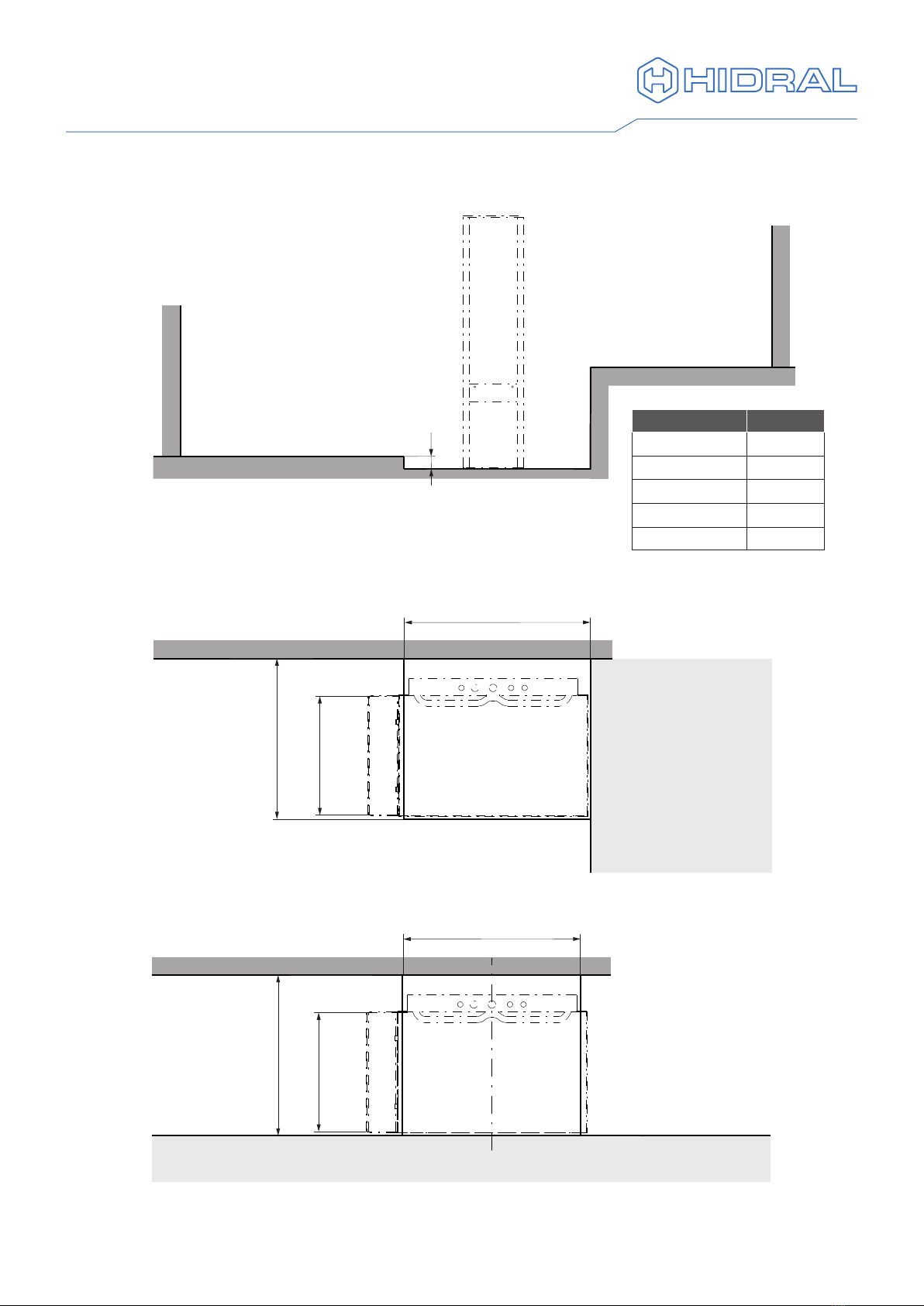
6 For the lower protection option, check that the pit dimensions are correct.
- F Pit depth
R (mm) F (mm)
≤ 400 ≥30
400< ≤ 700 ≥45
700< ≤1000 ≥60
1000< ≤1300 ≥75
1300< ≤1500 ≥90
Upper
level
Lower
level
F
- Pit dimensions for 180º access: (A+255) x 1220
Upper levelLower level
1220
A+255
A
- Pit dimensions for 90º access: (A+255) x 1150
Upper level
Lower level
1150
A+255
A
ASSEMBLY INSTRUCTIONS
PH-300 VERTICAL LIFTING PLATFORM
IM-560en
Vers. 05
Page 9
7 Check that the existing construction meets the necessary requirements for the
assembly of the upper-level doors, according to alternative Ⓐfor the option of
direct attachment to ooring or Ⓑfor the option of attachment by means of a built-
in plate.
Ⓐ Direct attachment to ooring
- Maximum wall plastering or covering thickness of 35 mm.
≤35
ⒷAttachment by means of a built-in plate
- Gap at the edge of the upper-level measuring at least 210 mm in width and
clearance plus 320 mm in length, centred with the position of the door.
- Structural concrete surface to attach the plate at a maximum distance from
oor level of 100 mm.
- Maximum wall plastering or covering thickness of 35 mm.
PL+320
210
75
≤100
≤100
210
≤35
IM-560en
Vers. 05
Page 10
ASSEMBLY INSTRUCTIONS
VERTICAL LIFTING PLATFORM PH-300
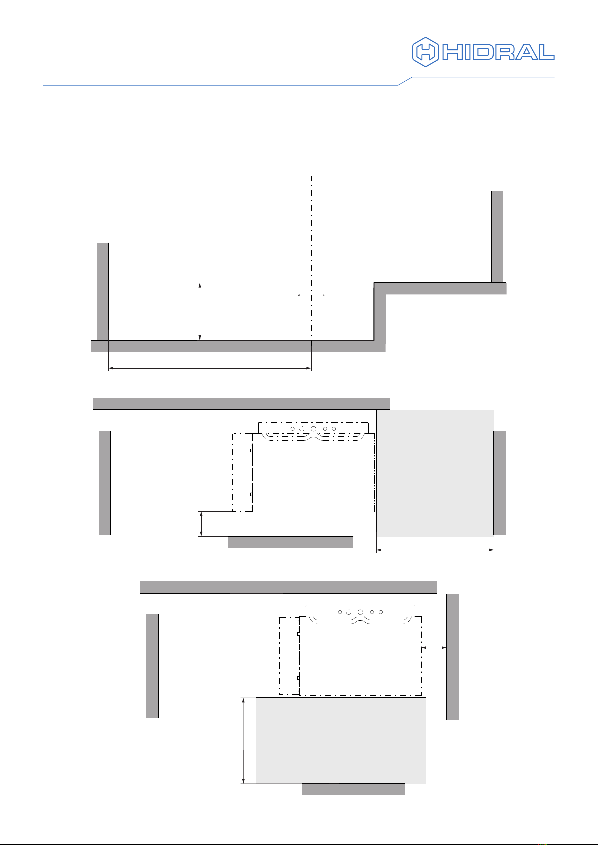
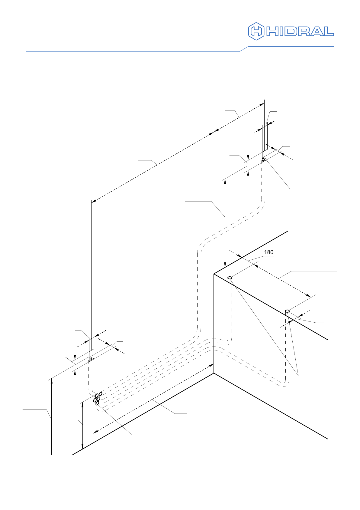
8 For the built-in push button panel option, check that the channels made begin
and end approximately as indicated for alternative Ⓐwith a cabinet on the lower
landing or Ⓑwith a cabinet on the upper landing.
ⒶCabinet on lower landing
910 for PL=800
1010 for PL=900
850÷1050
55
55
130
2050
30
Electrical inlet
600
850÷1050
55
55
130
750
1900
For upper
landing door
Without upper
landing door

ASSEMBLY INSTRUCTIONS
PH-300 VERTICAL LIFTING PLATFORM
IM-560en
Vers. 05
Page 11
ⒷCabinet on upper landing
600
180
910 for PL=800
1010 for PL=900
850÷1050
55
55
130
2050
30
850÷1050
55
55
130
750
For upper
landing door
Without upper
landing door
600
IM-560en
Vers. 05
Page 12
ASSEMBLY INSTRUCTIONS
VERTICAL LIFTING PLATFORM PH-300
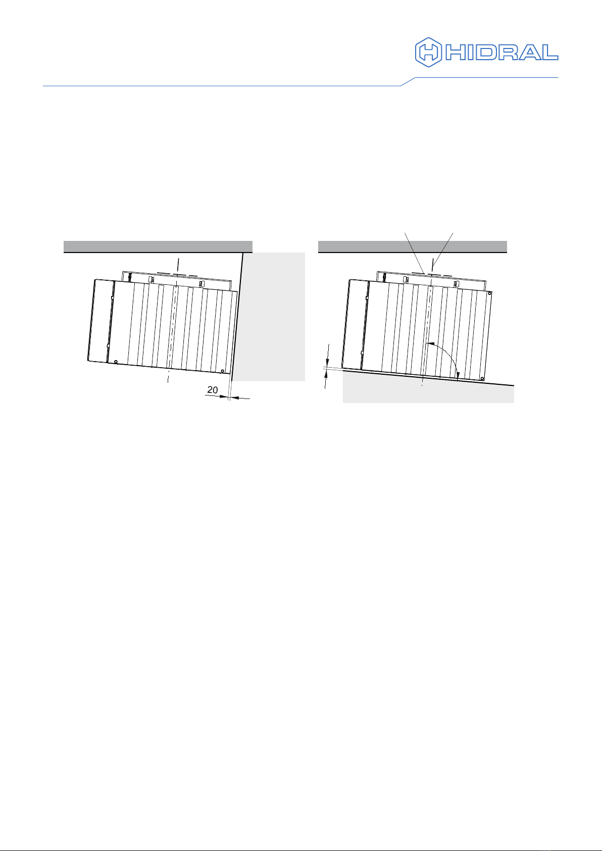
3. Guide assembly
1 Draw the guides axis on the ground. This must be perfectly parallel to the surface
of the upper access side, in the case of a 180º access, or at right angles to the
surface of the upper access side, in the case of a 90º access. To secure this
position, use the oor as a template, placing it on the ground 20 mm from the upper
access side and parallel to it. Draw a line on the ground, along the guide side,
using the oor as a reference and mark the centre of the oor. Remove the oor
from the ground.
20
90°
Guide axis markingLine paralell to the guide
2 Remove the front cover of the guide from the guide assembly.
3 Position the guide assembly on the wall and on the mark of the guide axis drawn
on the ground. Ensure that the guide and the line drawn in the previous section are
parallel.
4 Plumb the guide rail in both directions and adjust with the supports if necessary.
ASSEMBLY INSTRUCTIONS
PH-300 VERTICAL LIFTING PLATFORM
IM-560en
Vers. 05
Page 13
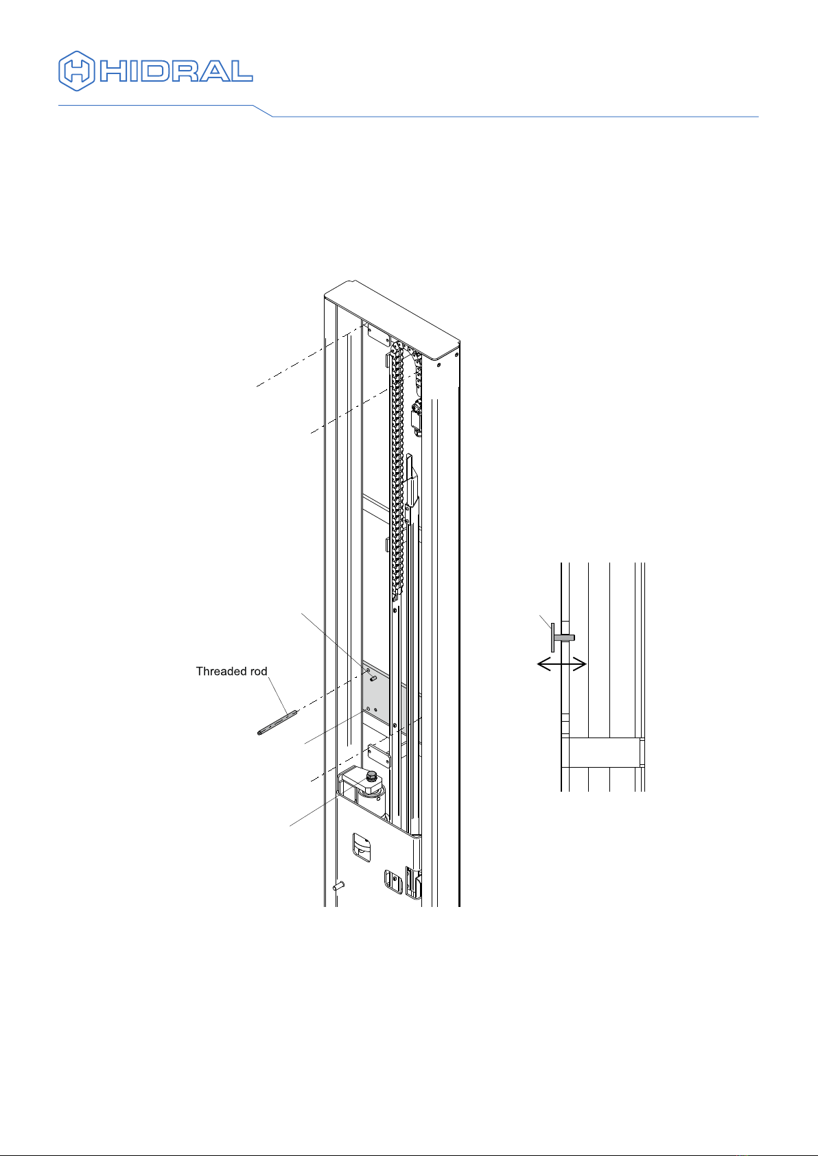
5 Using the guide as a template, make two Ø10 holes on the upper end of the guide
and another two on the upper section of the central plate. Once the rst hole is
drilled, insert a threaded rod to avoid the guide from deviating while the remaining
holes are made. In case an appropriate support for the upper part of the guide is
not available (see point 3 in section "2. Shaft check"), substitute the upper xation
anchorages for two additional xations in the lower holes of the central plate. In
case this plate is difcult to access, remove the bolt that xes the cylinder to the car
and move the car upwards; x the car securely in order to avoid accidents.
Adjustment
supports Adjustment
supports
Lower holes of the
fixation plate
Joint bolt between the
cylinder and the car
IM-560en
Vers. 05
Page 14
ASSEMBLY INSTRUCTIONS
VERTICAL LIFTING PLATFORM PH-300
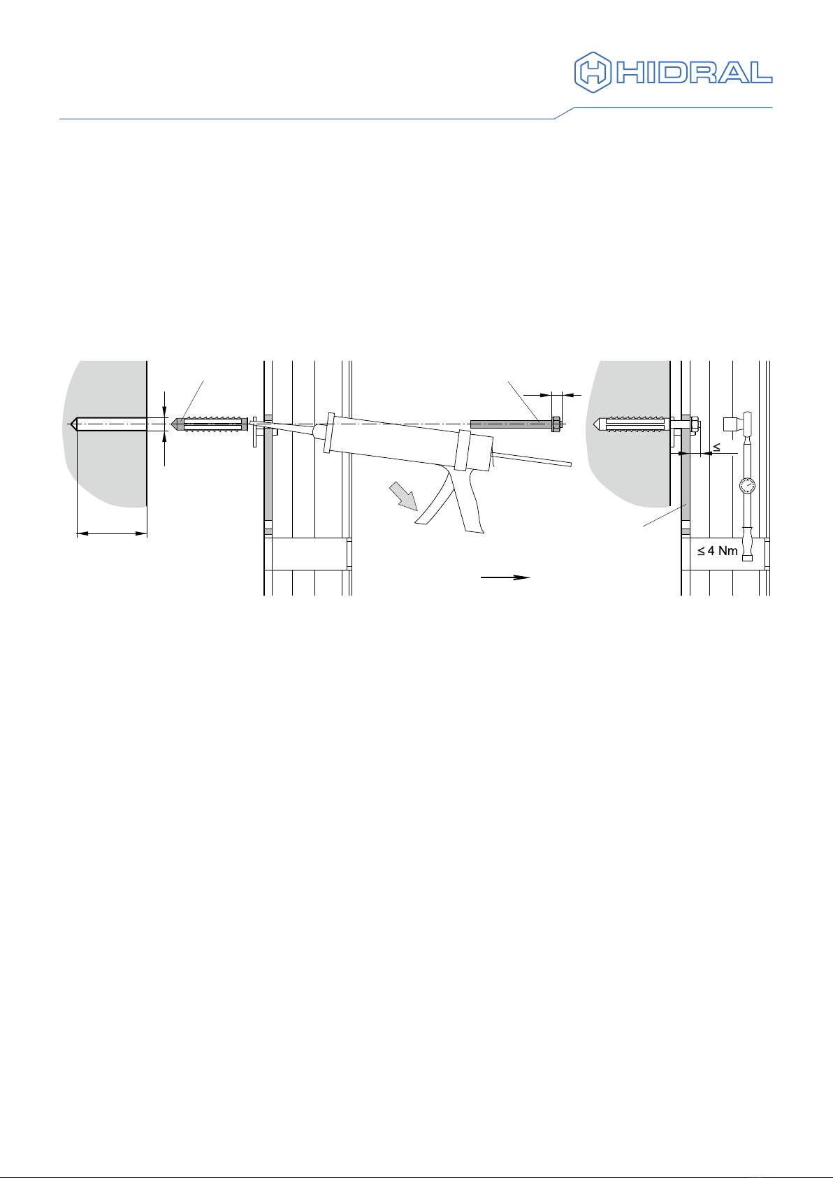
6 Separate the guide from the wall and redrill to Ø16 for a depth of 100 mm.
7 Insert the sheaves; previously, blow the holes.
8 Place the guide again in place.
9 Fill the holes starting from the bottom and making way towards the outside, with
5 strokes of the applicator. Immediately insert the threaded rods together with the
corresponding nuts and washers, to prevent the resin from hardening. The rod
shall be inserted fully and in such a way that it does not protrude more than 20 mm
from the crossbeams, to avoid interferences.
10 Wait for an hour without touching the threaded rods until the resin hardens
denitely. Tighten the nuts with a maximum torque of 4 Nm.
20
Rod, washer and nut
x5
> 1h
17
Crossbeam
100
Ø16
Sheave
ASSEMBLY INSTRUCTIONS
PH-300 VERTICAL LIFTING PLATFORM
IM-560en
Vers. 05
Page 15
4. Assembly of the machine cabinet
Access to the cabinet shall be suitable lighted and shall not be blocked in any way.
It shall be installed in a dry environment, and may not be installed outdoors.
The cabinet is foreseen for installation in a position adjacent to the guide assembly,
either on the lower level or on the upper level. Plastic channels are supplied to install
the hydraulic piping and electric connection cables so that these may be hidden,
taken the foreseen position into account. If the cabinet is installed in a different
position not adjacent to the guide, the hydraulic piping and the electric connection
cables shall be installed in appropriate conduits or channels (not supplied).
A working area of 550x700x2000 mm in front of the cabinet shall be guaranteed.
The machine cabinet shall be installed protected from high temperatures and
radiations to ensure that the temperature inside is between +5ºC and +40ºC.
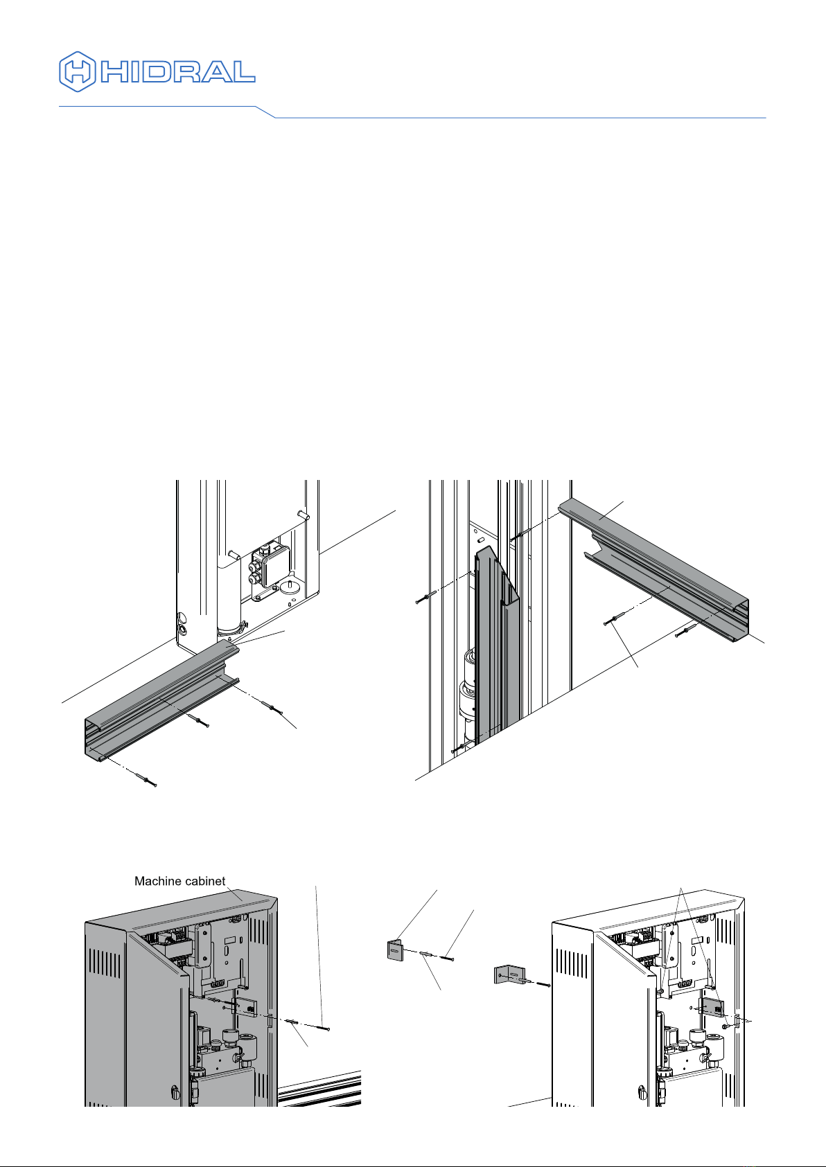
1 Attach the supplied conduit to hide the hydraulic and electrical connections
between the guide rail and the machine cabinet at the upper or lower end of the
guide rail, according to alternative Ⓐwith a cabinet on the lower landing or Ⓑwith
a cabinet on the upper landing. Use the supplied anchors.
60x110 conduit
Anchor for
Ø6 conduit
Ⓑ
Ⓐ
60x110 conduit
Anchor for
Ø6 conduit
2 Place the machine cabinet adjacent to the conduit and x it denitely to the wall.
Two additional xation brackets are supplied for the xation that allow the cabinet
to be installed slightly separated from the wall.
Fixation brackets Bolt M5x12
Screw ST 5.5x45
Plug Ø8
Screw ST 5.5x45
Plug Ø8
Location of the cabinet

IM-560en
Vers. 05
Page 16
ASSEMBLY INSTRUCTIONS
VERTICAL LIFTING PLATFORM PH-300
5. Hydraulic installation
1 Insert the bent end of the exible pipe through the lower opening in the machine
cabinet and the straight end of the pipe through the lower hole in the guide rail.
2 Screw the bent end of the pipe to the shut off valve and screw the straight end of
the pipe to the oil inlet of the cylinder. Reject the protection plugs.
Flexible pipe
Bent end
3 Fill the hydraulic power unit with the supplied oil.
Funnel

ASSEMBLY INSTRUCTIONS
PH-300 VERTICAL LIFTING PLATFORM
IM-560en
Vers. 05
Page 17
6. Electrical installation
6.1. Guide electrical installation
1 Plug in the guide rail connection cable to the control board in the machine
cabinet and bring the cable through the channel towards the guide rail. Open the
connection box in the guide rail assembly and plug in the connectors in this end.
2 Fix the cable to the guide using a cord to the upper section of the travelling cord
support.
Control board
Guide connection
cable
Fixation
6.2. Machine cabinet electric installation
1 Using an allen key, remove the knob in the main switch and the embellisher to gain
access to the protection outer casing and connect the supply of the machine to the
electric board.
Embelisher
Protection
IP switch
IM-560en
Vers. 05
Page 18
ASSEMBLY INSTRUCTIONS
VERTICAL LIFTING PLATFORM PH-300
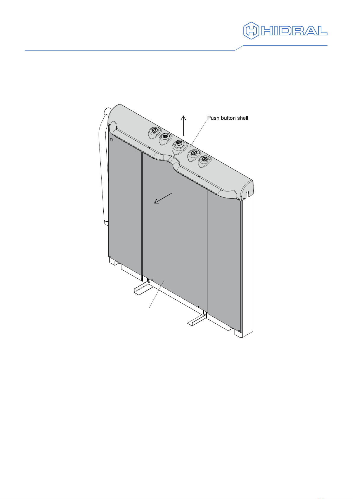
7. Vehicle installation
1 Remove the xation bolts for the push button shell, unplug the connector and
remove the shell.
2 Remove the lower bolts in the front vehicle cover and remove it.
Cover
3 Position the vertical structure next to the cart enough to insert the cables from the
guide rail and position the cable support plate.
4 Bring the vertical structure towards the guide and insert the rods in the cart in the
vertical structure, until they are in contact with the holes. Fix the vertical structure
with the four M12 biaseled ring nuts.
5 Fix the cable support plate to the vertical structure with four M4 nuts.
Table of contents
Popular Lifting System manuals by other brands

TOOL WAREHOUSE
TOOL WAREHOUSE HMWT-1000 quick start guide

BraunAbility
BraunAbility 02 Series Service manual

Braun
Braun FMVSS No. 403 Quick reference installation sheet

morse
morse 520-115 Operator's manual

Aqua Creek Products
Aqua Creek Products REVOLUTION F-702RLNA manual

Altrex
Altrex MiTower Assembly guide

Aqua Creek Products
Aqua Creek Products Scout Excel F-SCTXL manual

Tractel Group
Tractel Group pakrol 1 Operating and maintenance instructions

HAMACO
HAMACO ML-150-45V-D12 user manual

CASCOS
CASCOS TV2000H user guide

Harbor Freight Tools
Harbor Freight Tools PITTSBURGH 56617 Owner's manual & safety instructions

SINOLIFT
SINOLIFT ETM Series operating manual


