HIDROCONTROL WATER DRIVE W-Drive2M2M/08 User manual
MANUAL DE INSTALACIÓN / USER MANUAL
VARIADOR DE FRECUENCIA PARA SUMINISTRO DE AGUA
A PRESIÓN CONSTANTE
SERIE WATER DRIVE

2
CONTENIDO
ADVERTENCIA WARNING 3
GUÍA DEL COMPRADOR GUIDE TO PURCHASE 4
1. Selección de bombas 1. How to choose pump 4
2. Adaptador para conexiones con largas distancias (ACL) 2. Long Connecon Adapter (LCA) 4
3. Filtro EMI 3. EMC lter 4
SUMINISTRO Y CONTENIDO PACKAGE CONTENTS 5
GUÍA RÁPIDA DE ARRANQUE START UP PROCEDURE 5
Instalación hidráulica Hydraulic installaon 5
Instalación eléctrica Electrical installaon 5
DESCRIPCIÓN DE LA PANTALLA DEL WATER DRIVE SCREEN DESCRIPTION OF WATER DRIVE 6
Descripcion de cada botón Keyboard use 7
CONFIGURACIÓN INICIAL PROCEDURE 7
GENERALIDADES GENERAL REMARKS 8
Descripción del producto Product descripon 8
Sistemas de Presurización Pressurizaon groups 9
Condiciones de uso Usage condion 9
CARACTERÍSTICAS TÉCNICAS TECHNICAL FEATURES 9
Protección Protecons 10
FUNCIONAMIENTO Y USO FUNCTIONING AND USE 11
Conexión eléctrica Electrical connecon 11
Selección del cable de alimentación en función de la
distancia
Secon power supply cable linked to cable
length.
12
Conexiónes adicionales Addional connecons 12
Como conectar un switch otador externo How to connect a dry running oat 13
Conectar una segunda bomba a plena carga (ON/OFF): How to connect a second pump ON/OFF (xed
rate)
13
Conguración Relay Relay Conguraon 13
Conguración Booster(Bomba ON/OFF) Booster Conguraon (ON/OFF pump) 13
Booster Operaon Booster Operaon 13
Ejemplo de conexión para el Modo Booster
(bomba ON / OFF - versión MM / MT)
Connecon example for Mode Booster
(pump ON / OFF – MM/MT version)
14
Conguración Mulbomba Mulpump Conguraon 14
Menú Soware Menu 15
Conguración Conguraon: 16
Calibración del sensor de presión Sensor calibraon 16
Comunicación Communicaon 16
Conexión hidráulica Hydraulic Connecon 16
Notas de instalación Installaon Notes 17
Diagrama de instalación hidráulica Hereaer a typical system diagram with surface
pump sucon head
17
SOLUCIÓN DE PROBLEMAS Y MANTENIMIENTO TROUBLESHOOTING AND MAINTENANCE 18
MENÚ AVANZADO EXTENDED MENU 21
TABLA DE PARÁMETROS PARAMETER TABLE 22
ES EN
3
SERIE WATER DRIVE
ADVERTENCIA WARNING
PELIGRO DANGER
Riesgo de lesiones personales y pérdidas materiales.
DESCARGA ELÉCTRICA
Riesgo de lesiones por descargas eléctricas.
Risk of personal injury and property if not complied with
the requirements.
ELECTRIC SHOCK
Risk of damage to property or the environment if not
complied with the requirements.
ADVERTENCIA WARNING
Riesgo de daños a la propiedad o el medio ambiente. Risk of damage to property or the environment
if not complied with the requirements.
ADVERTENCIA WARNING
Antes de instalar y de usar el producto lea este manual de
instalación en su totalidad. La instalación y mantenimiento deben
ser realizados por personal calicado.
HIDROCONTROL no se hace responsable de los daños causados
por un uso inadecuado del variador WATER DRIVE, por una mala
instalación, manipulación no autorizada, el uso de refacciones no
orginales, lo cual anularía automácamente la garana.
Before installing and using the product read this book
in all its parts. Installaon and maintenance must be
performed by qualied personnel in accordance with
current regulaons.
HIDROCONTROL will not be held responsible for any
damage caused by improper or prohibited use and is
not responsible for any damages caused by a not correct
installaon or maintenance.
The use of non-original spare parts, tempering or
improper use, make the product warranty null.
ADVERTENCIA WARNING
El variador WATER DRIVE debe ser instalado de acuerdo con el
apartado tulado como “funcionamiento y ulización”.
En la instalación del variador WATER DRIVE enfriado por agua,
la red hidráulica debe estar diseñada para evitar una presión
excesiva, como la provocada por los golpes de ariete. Los
disposivos instalados para proteger contra el exceso de presión
deben ser revisados periódicamente.
El WATER DRIVE es un disposivo eléctrico, si su estructura
mecánica es dañada por la presión excesiva, las fugas de agua
pueden ser perjudiciales para los componentes eléctricos.
WATER DRIVE must be installed as described in the
paragraph “Funconing and Use” You must project
correctly the hydraulic connecon of WATER DRIVE to
avoid pressure shocks. The shock absorber, installed to
avoid pressure shocks, must be keep under a correct
maintenance.
WATER DRIVE is an electric device, if the case will be
damage by pressure shocks a possible water inltraon
could be dangerous due to the contact between electric
components and the water ow.
PELIGRO DANGER
El variador WATER DRIVE está cercado bajo la CE, pero en el
caso de una incorrecta instalación puede causar interferencias
electromagnécas.
En el caso de interferencia electromagnéca,
antes de cada procedimiento, asegúrese de que el variador WATER
DRIVE esté desconectado de la fuente de alimentación.
No lleve a cabo ninguna maniobra con el variador WATER DRIVE
encendido.
La puesta en marcha del variador WATER DRIVE debe ser realizada
por personal calicado.
El variador WATER DRIVE debe estar protegido por un interruptor
térmico y conectado a un sistema de erras.
WATER DRIVE is CE labelled but in the case of wrong
installaon can cause electromagnec interference.
Verify the correct operaon of other electronic devices
with WATER DRIVE on and running.
Malfuncon of equipment can be harmful to people and
property.
In the case of electromagnec interference contact
technical support and stop the plant.
Before any intervenon censure that the WATER DRIVE is
disconnected from the electricity supply.
Do not aempt operaons with the WATER DRIVE open
The connecon of the WATER DRIVE to the electric panel
must be carried out by qualied personnel in accordance
with current norms
WATER DRIVE must be protected by a thermal switch.
WATER DRIVE must be connected to an ecient earthing
system.
ES EN
4
GUÍA DEL COMPRADOR GUIDE TO PURCHASE
Gracias por su preferencia hacia nuestros productos, y por
elegir nuestro equipo WATER DRIVE que gracias a su alta calidad
y eciencia permite controlar equipos con un alto grado de
exactud. Considere la siguiente infomación para ulizar e
instalar correctamente su variador WATER DRIVE.
Thanks to have bought WATER DRIVE! We would
like to noce some useful informaon to correctly
use and install WATER DRIVE and the available
accessories.
1. Selección de bombas 1. How to choose pump
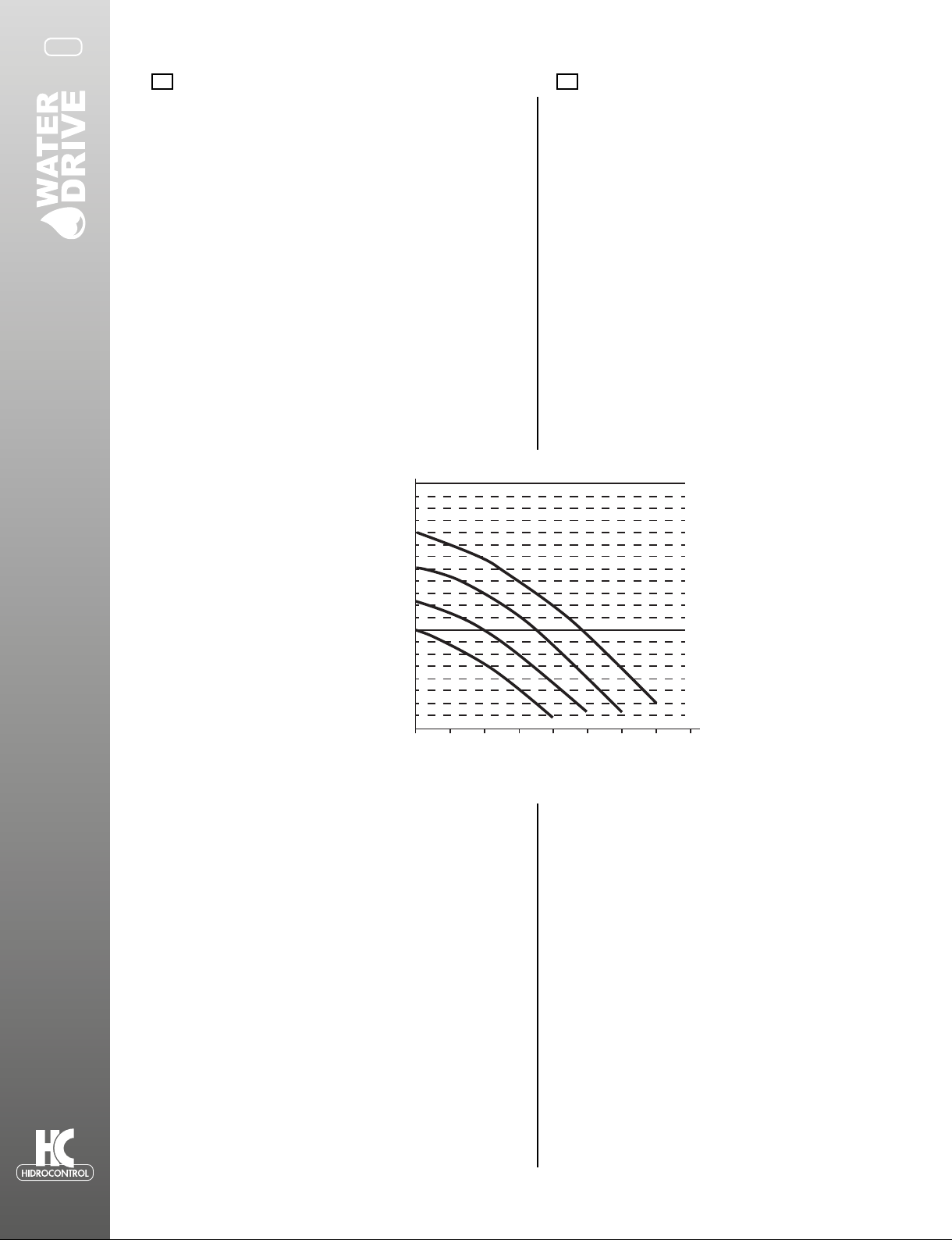
Con el n de aprovechar adecuadamente el funcionamiento
del variador WATER DRIVE debe tener especial cuidado en
la selección de la motobomba. Un variador WATER DRIVE
por su propia naturaleza acciona la motobomba a diferentes
frecuencias con diferentes ujos de demanda, logrando así
alcanzar un alto ahorro energéco y un incremento en la vida úl
de la motobomba. Para obtener el mejor comportamiento, debe
elegir la curva correcta y una motobomba con caracteríscas
adecuadas (ver g.1), por lo general las bombas centrífugas
están diseñadas para poder trabajar a diferentes frecuencias
(bajo el mandato de un variador WATER DRIVE). La carga y
caudal de la bomba debe ser adecuados a las necesidades del
sistema.
to take advantage of performance of WATER DRIVE
it is essenal to choose the correct pump. The
inverter pilots the pump on several frequencies
depending on the variaon of ow. This is why it
is possible to save energy and to increase life me
of the pump. For having correct behaviours it is
essenal to choose a
pump with slope characterisc curve (see g.1),
usually centrifugal pumps; this kind of pump
permits the WATER DRIVE to pilots pump at
variables speed. The head and capacity of the pump
must correct for request of the plant.
2. Adaptador para conexiones de largas
distancias (ACL)
2. Long Connection Adapter (LCA)
El cable de conexión entre el variador WATER DRIVE y una
motobomba, puede crear un efecto capacivo que afecte el
correcto funcionamiento entre el variador WATER DRIVE y la
motobomba. Para cancelar la distorsión creada por el cable,
HIDROCONTROL ofrece un adaptador para las conexiones de
gran longitud L> 15m, hasta 80 metros. Este accesorio se uliza
generalmente en aplicaciones con bombas sumergibles y se
debe cozar por separado.
The connecon cable creates, between WATER
DRIVE and pump, a capacive eect. For removing
the disturbance Hidrocontrol produces an adapter
forlong connecon L>15mt (50 feet), up to 80 mt
(260feet) of cable.
This device is normally used with submersible
pumps in well applicaons and should be quoted
separately.
3. Filtro EMI 3. EMC lter
Los variadores WATER DRIVE están cercados con la EMI para
uso domésco. Cuando se instala en un ambiente especialmente
sensible a las interferencias electromagnécas, HIDROCONTROL
ene a su disposición ltros EMI, los cuales se deben instalar
entre el suministro de voltaje y el variador WATER DRIVE con
el n de eliminar cualquier interferencia (se debe cozar por
separado).
Hidrocontrol inverters have domesc use EMC
approval. If inverter is installed in enviroments
parcularly sensive to electromagnec
interference Hidrocontrol makes available addional
EMI lters, to be installed between the supply
and inverter, so as to eliminate (should be quoted
separately).
100
80
65
50
40
20
0 2.2 3.8
60 Hz
40 Hz
45 Hz
50 Hz
5 6.5 7 7.5 Q(lps)
H(m)
3
ES EN
Fig.1
5
GUÍA RÁPIDA DE ARRANQUE START UP PROCEDURE
Instalación hidráulica Hydraulic Installation
A connuación se presenta un diagrama a modo de ejemplo sobre
la correcta conexión del WATER DRIVE en la red hidráulica, para
obtener más detalles e instrucciones, consulte el apartado de “Uso y
Funcionamiento”
Here aer a scheme, as example, for more details and
warnings see the secon “Funconing and Use”
Instalación eléctrica Electrical Installation
Enseguida usted puede observar el diagrama pico de conexiones
para la alimentación al WATER DRIVE y a la motobomba. Para
una información más detalla consulte el apartado de “Uso y
Funcionamiento”.
Here aer a scheme, as example, for more details and
warnings see the secon “Funconing and Use”.
SUMINISTRO Y CONTENIDO PACKAGE CONTENTS
WATER DRIVE está integrado a un tubo de 1.25” y cuenta con
terminales de fácil montaje y cableado.
WATER DRIVE is provided on metal pipe 1 ¼ “and easily
accessible terminals for wiring.
U
BOMBA
POWER
V W L N
J1
F
BOMBA
BOMBA
ALIMENTACIÓN
ALIMENTACIÓN
ES EN
6
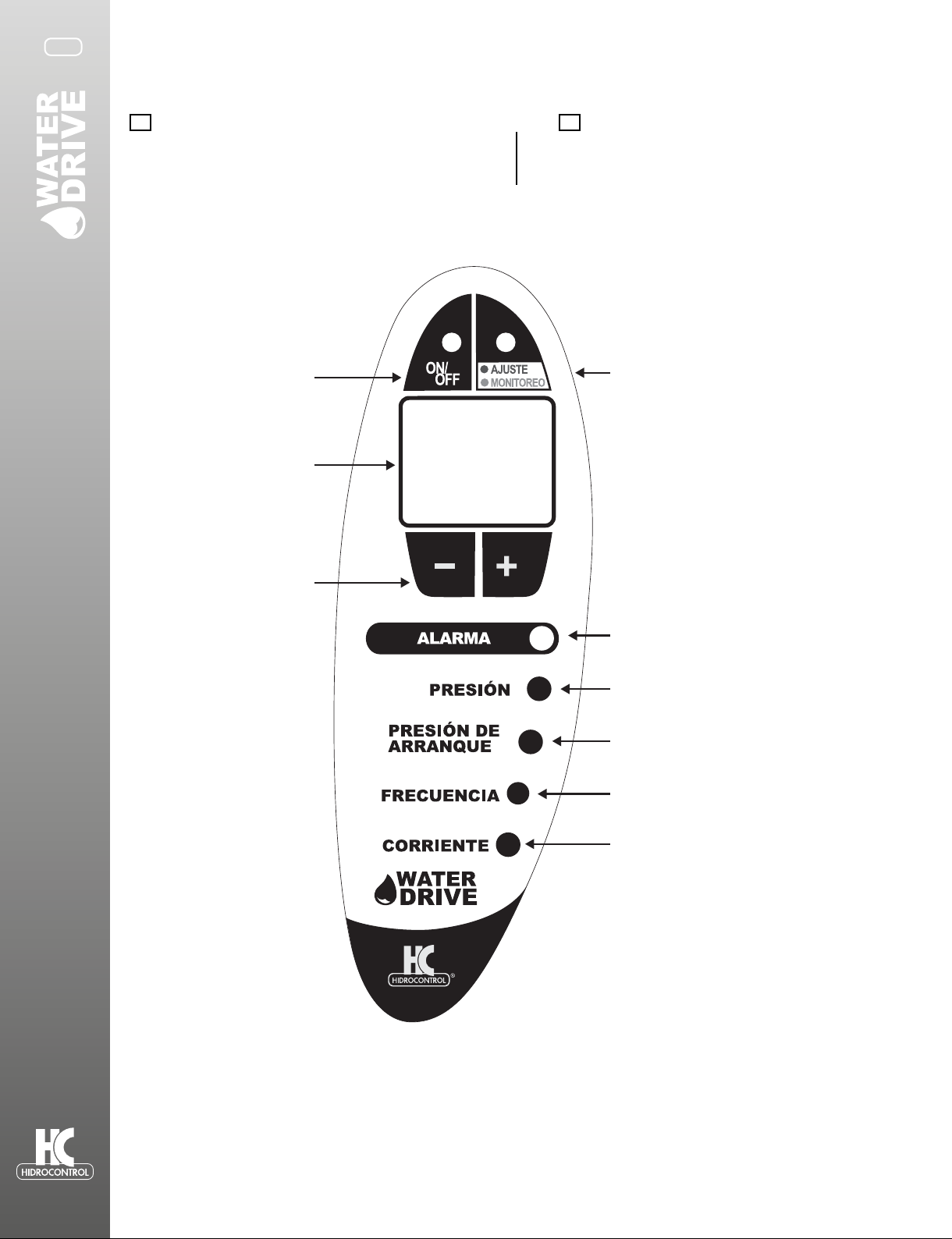
DESCRIPCIÓN DE LA PANTALLA
DEL WATER DRIVE SCREEN DESCRIPTION OF
WATER DRIVE
Botón ON / OFF: para encender O
apagar el Water-Drive.
ON/OFF button: to put on standby
the Water-Drive.
Botón AJUSTE/MONITOREO: para
modificar o visualizar algún parámetro.
SAVE/DISPLAY Button: to change and to
save the set value.
Indicadores leds para cada valor mostrado en el
display.
Led indicators for the value shown on the display.
Led parpadeando de color rojo: indica alarma.
Led flashing red: indicates alarm.
Presión de la red.
Restart pressure.
Presión de arranque.
Restart pressure.
Frecuencia actual.
Frequency.
Corriente de la motobomba.
Motor Current.
Botones de navegación “+” y
“-“ para desplazarse sobre los
parámetros.
Keys + and – scroll the
parameters and change the set
values-
Display
ES EN

7
Botón/Buon Acción Eect
ON/OFF
Permite encender o apagar la operación del WATER
DRIVE sobre la motobomba.
- Mantener presionado por 5 segundos.
- Luz encendida: El WATER DRIVE está en operación.
- Luz apagada: El WATER DRIVE está apagado.
To set the device in stand by and switch o the pump.
- Keep pressed for 5 seconds.
- Light on= device is operang.
- Light o= device in stand by.
AJUSTE /
MONITOREO
Permite pasar del modo ajuste al modo de supervision
(Monitoreo).
-Mantener presionado por 1 segundo para entrar al
modo de monitoreo.
-Mantener presionado por 5 segundos para entrar en el
modo de ajuste.
-Presione una segunda vez para grabar algún valor y
regresar al modo monitoreo.
It allows to switch from display mode to set mode:
-Press for 1 second to see the value set.
-Press for 5 second to enter into set mode.
-Press a second me to save the value and return to display
mode.
+/-
Si el led del botón AJUSTE/MONITOREO está encendido
de color verde, al presionar estos botones podemos
visualizar los valores de operación en empo real de la
motobomba.
Si está encendido en color rojo, podemos modicar el
valor seleccionado.
If LED SAVE / DISPLAY green= it allows to scroll through the
parameters.
If LED SAVE / DISPLAY red= it allows to change the selected
parameter value.
Descripción de cada botón Keyboard use
CONFIGURACIÓN INICIAL PROCEDURE
Al energizar el variador WATER DRIVE, después de 2 segundos
mostrará la siguiente pantalla.
Power the WATER DRIVE in 2 seconds it will be displayed the
version of the soware and the model of the device.
MM
01
Muestra el valor de corriente que usted podrá ajustar. Presione
el botón “+” para aumentar y “–” para disminuir hasta obtener el
valor deseado.Presione el botón AJUSTE/MONITOREO para grabar
el valor deseado y para pasar al siguiente parámetro.
Displayed the value of current to be set. Press the + buon to
increase the value and - to decrease.
Press the SAVE key to save the value and move to the next.
6.8
Muestra el valor de la presión del sistema que usted podrá ajustar.
Presione el botón “+” para aumentar y “–” para disminuir
hasta obtener el valor desado. Presione el botón AJUSTE/
MONITOREO para grabar el valor deseado y para pasar al siguiente
parámetro.
Displayed the value of System Pressure to be set. Press the +
buon to increase the value and - to decrease.
Press the SAVE key to save the value and move to the next.
3.0
Muestra el valor de presión de arranque que usted podrá ajustar.
Presione el botón “+” para aumentar y “–” para disminuir hasta
obtener el valor deseado. Presione el botón AJUSTE/MONITOREO
para grabar el valor deseado.
La conguración inicial ha terminado.
Displayed the value of Restart Pressure to be set. Press the +
buon to increase the value and - to decrease.
Press the SAVE key to save the value. The installaon
procedure is nished.
ES EN
8
2.6
El WATER DRIVE graba los valores y muestra la palabra “OF”
para indicar que la motobomba no está energizada.
The device saves the parameters and displays OF (OFF). the
pump is not powered. Acvates the pump.
OF
Para acvar la motobomba presione el botón ON/OFF hasta
que el display muestre la palabra “ON”.
To acvate the pump push the ON/OFF buon ll the led
display shows ON.
ON
El display muestra el valor de presión actual en el sistema. The LED display shows the value of the measured pressure
of system.
3.0
Durante la operación del WATER DRIVE podemos visualizar
los valores sensados en los parámetros (presión del
sistema, presión de arranque, corriente consumida por
el motor y frecuencia a la cual el motor esta operando)
presionando los botones “+” y “-” .
Para leer los valores de los parámetros, presione el botón
AJUSTE/MONITOREO por un segundo. El led indica a que
parámetro corresponde el valor visualizado.
During operaon, you can read the measured values of
the parameters (pressure in the system, restart pressure,
current consumpon of the pump and frequency at which
the pump is running) by pressing the + / - keys.
To read the values set of the parameters press the SAVE /
DISPLAY buon for 1 second. The link between the value
displayed and the parameter is idened accordingly by
the LED ashing.
Sendo de rotación: Rotaon sense:
En caso de necesitar que el motor invierta su sendo de
giro es posible hacerlo a través del menú extendido o
invirendo 2 de las 3 fases de conexión de la motobomba.
In case of need to reverse the rotaon sense of the pump
is possible to do so via soware, entering the extended
menu (see paragraph) or reverse the connecon of two
wires on WATER DRIVE terminal or on the pump.
GENERALIDADES GENERAL REMARKS
Este manual ofrece la información esencial para la correcta
instalación, uso y mantenimiento del
WATER DRIVE.
Es muy importante que el usuario y/o instalador lea
cuidadosamente este manual antes de realizar cualquier
operación del equipo. Una instalación incorrecta puede
causar fallas o la anulación de la garana.
This manual intends to provide essenal informaon for
the installaon, use and maintenane of the WATER DRIVE.
It is important that the user and/or installer carefully
reads the manual before installing and using the product.
Incorrect use may cause faults and result in the annulment
of the
guarantee terms.
Descripción del producto Product Description
El WATER DRIVE es un variador de frecuencia enfriado por
agua para sistemas de presión constante.
WATER DRIVE regula automácamente la velocidad de una
motobomba en función de la necesidad de agua.
The WATER DRIVE is a variable frequency drive (inverter)
for liing units under constant pressure.
WATER DRIVE, according to the actual water requirements
undertakes the automac regulaons of the number of
revs of the electro-pump whilst maintaining the system
pressure constant.
WATER DRIVE está disponible en los siguientes modelos: The WATER DRIVE is available in the following versions:
W-Drive2M2M/08: Alimentación monofásica al variador y
alimentación monofásica para la motobomba.
W-Drive2M2M/08: inverter water coooled, single-phase
line for single-phase pump.
W-Drive2M2T/10: Alimentación monofásica al variador y
alimentación trifásica para la motobomba.
W-Drive2M2T/10: inverter water coooled, single-phase line
for three-stage pump.
ES EN
9
Sistemas de Presurización Pressurization groups
Es posible congurar el WATER DRIVE para controlar un segundo
motor a plena carga, en este modo el WATER DRIVE controlará el
arranque y paro de una bomba a plena carga controlada por un
arrancador externo, para lograr esto se debe interrumpir la señal de
marcha del arrancador externo mediante el rele del WATER DRIVE.
Para esta aplicación se deben seleccionar bombas con las mismas
caracteríscas hidráulicas.
*Una conguración mulbomba (modo ADVANCED) está disponible
para trabajar hasta con 8 bombas.
En una conguración de un variador maestro (MASTER) y 7
variadores esclavos (Slaves). Siendo el inversor maestro el que
determina la operación de los esclavos
• The WATER DRIVE allows to drive a second pump ON/OFF
at a xed rate (booster pump). For correct installaon, follow
the wiring diagram and instrucons refer to paragraph
“Addional connecons”.
• A mulpump conguraon (ADVANCED model) is available
for running ll 8 pumps.
The ADVANCED version is composed by a Master that
pilots ll 7 Slaves.
The inverter Master determines the funcon of the
system.
*La instalación debe ser realizadas por personal calicado
IMPORTANTE: Para esta aplicción se deben seleccionar bombas con
las mismas caracteríscas: potencia motor (hp), prevalencia (Hmax).
Installaon must be performed by qualied personnel
IMPORTANT: The pumps used must be of the same
characteriscs: power engine (hp), head (Hmax).
Condiciones de uso Usage Condition
Temperatura de operación: 0°C + 40°C.
Máxima humedad: 50% a 40°C (sin condensación).
Temperatura del líquido: 1°C a 40°C.
Tipo de líquido a bombear: Agua libre de productos químicos o
residuos (pH entre 5 a 9).
Operaonal temperature: 0°C to +40°C
Max.humidity: 50% at 40°C (no condensate)
Temperature of uid: +1°C +40°C
Nature of uid: water with no chemical add (ph 5 to 9) and
no debris.
ADVERTENCIA WARNING
WATER DRIVE debe ser instalado en ambientes que estén protegidos
contra la congelación e intemperie.
Se deben dimensionar correctamente las conexiones hidráulicas del
WATER DRIVE y su ubicación para evitar golpes de presión. El tanque
precargado, así como elementos de protección de la red hidráulica
deben ser revisados periódicamente.
El WATER DRIVE no debe trabajar con líquidos abrasivos, sustancias
sólidas o brosas, así como líquidos inamables o explosivos.
WATER DRIVE must be installed in environments that are
protected from freezing and weather-proof.
You must project correctly the hydraulic connecon of
WATER DRIVE to avoid pressure shocks. The shock absorber,
installed to avoid pressure shocks, must be keep under a
correct maintenance.
WATER DRIVE cannot be used on pipes containing abrasive
liquids, brous solid substances or inammable liquids or
explosives.
CARACTERÍSTICAS TÉCNICAS TECHNICAL FEATURES
Frecuencia de salida 5-100 hz Output frequency 5-100 hz
Tiempo de aceleración 1.5 - 5 s Acceleraon me 1.5 - 5 s
Seguridad eléctrica,
compabilidad
electromagnéca
EN60730
EN61000-6-3
EN61000-6-4
Electrical safety
Electromagnec
compability
EN60730
EN61000-6-3
EN61000-6-4
Display 2 dígitos alfanuméricos Display 2 digit alphanumeric
Posición de montaje Cualquiera Assembly posion Any
Presión de regulación 4-116 psi Pressure to be set 0.3-8 bar
Máxima sobrepresión 174 psi Max overpressure 12 bar
Temperatura ambiente de
funcionamiento 5 - 40 °C Operaonal Ta 5 - 40 °C
Grado de protección IP65 Protecon category IP65
Conexión entrada / salida 1 ¼” macho Input/output 1 ¼” male
Dimensiones 33 x 22 x 15 cm Dimension 33 x 22 x 15 cm
Peso 2kg Weight 2kg
ES EN

10
W-DRIVE2M2M/08
Alimentación 1x230 VCA (170 a 270
VCA) Power supply 1x230 VAC (170 ÷ 270
VAC)
Potencia máxima (P2) 230V 1.1 kw (1.5 hp) Max pump power (P2)
230VAC single phase 1.1 kw (1.5 hp)
Amperaje máximo 8 Phase current 8
W-DRIVE2M2T/10
Alimentación 1x230VCA (170 a
270VCA) Monophase power supply 1x230 VAC (170 ÷ 270
VAC)
Potencia máxima (P2) 230V 2.2 kw (3 hp) Max pump power (P2) 230Vac
three-phase 2.2 kw (3 hp)
Máxima corriente de fase 10 Max. phase current 10
Protección Protections
En caso de alguna anomalía el WATER DRIVE apaga la
motobomba y realiza intentos automácos o programados
para el restablecimiento del sistema.
In the event of anomaly condions WATER DRIVE protects
the autoclave by switching o, but to ensure water,
aempts automac or programmed reset operaons.
Protección Restablecimiento Type of
protecon Reset
Bajo voltaje
Automáco (ver apartado
de Solución de Problemas y
Mantenimiento)
Power voltage
too low
Automac (see “Troubleshoong &
maintenance”).
Alto voltaje
Automáco (ver apartado
de Solución de Problemas y
Mantenimiento)
Power voltage
too high
Automac (see “Troubleshoong &
maintenance”).
Cortocircuito
Intentos automácos (candad
programable de fábrica: 5
intentos) después de estos
intentos es necesario el
restablecimiento manual.
Short circuit
Automac aempts (n°
programmable - factory default 5);
on exhausng the reset aempts you
need to restart manually*.
Voltaje de salida mayor
al umbral permido
durante más de un
minuto
Intentos automácos (candad
programable de fábrica: 5
intentos) después de estos
intentos es necesario el
restablecimiento manual.
Output voltage
above threshold
for over 1 min.
Automac aempts (n° threshold for
over 1 min. programmable - factory
default 5);
on exhausng the reset aempts you
need to restart manually*.
Temperatura del agua
por encima de 75°C
Automáco (ver apartado
de Solución de Problemas y
Mantenimiento)
Water
temperature
above 75 °C
Automac (see “Troubleshoong &
maintenance”).
Presión insuciente Intentos de arranques
automácos.
Insucient
pressure in Automac restart aempts *
Falta de agua o aire en
la tubería
Intentos de arranques
programables.
Lack of water or
air in the pump n° programmable aempts**
Fallo del sensor Restablecimiento manual. Pressure sensor
fault ---
Golpe de ariete Intentos de arranques
automácos. Pressure shock Automac
Anbloqueo (sólo
versión 2M2M)
Si la bomba es detenida por más
de 24 horas, el WATER DRIVE
reinicia la bomba elevando la
presión en 0.5 bares.
An-lock (only
vers MM)
If the pump is stopped for more than
24 hours, the device restarts the
pump raising the pressure of 0.5 bar.
ES EN
11
*Número programable de intentos para el restablecimiento del
sistema (programado de fábrica a 5 intentos).
Si al terminar los intentos programados no se restablece el servicio, es
necesario hacer lo siguiente:
* programmable number of automac restart aempts.
(factory default 5).
On exhausng the reset aempts you need to:
1. Desenergizar el WATER DRIVE. 1. disconnect power
2. Espere a que la pantalla se apague. 2. wait for display to switch o
3. Energice de nuevo el WATER DRIVE. 3. re-power
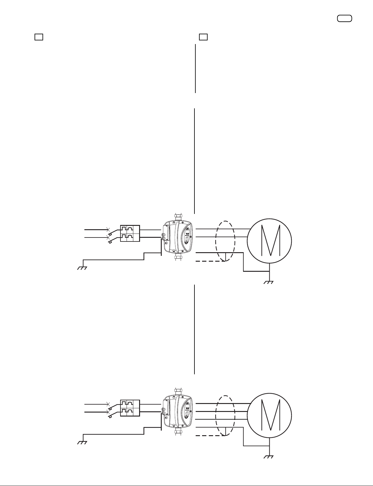
FUNCIONAMIENTO Y USO FUNCTIONING AND USE
Conexión eléctrica Electrical connection
(Modelo W-Drive2M2M)
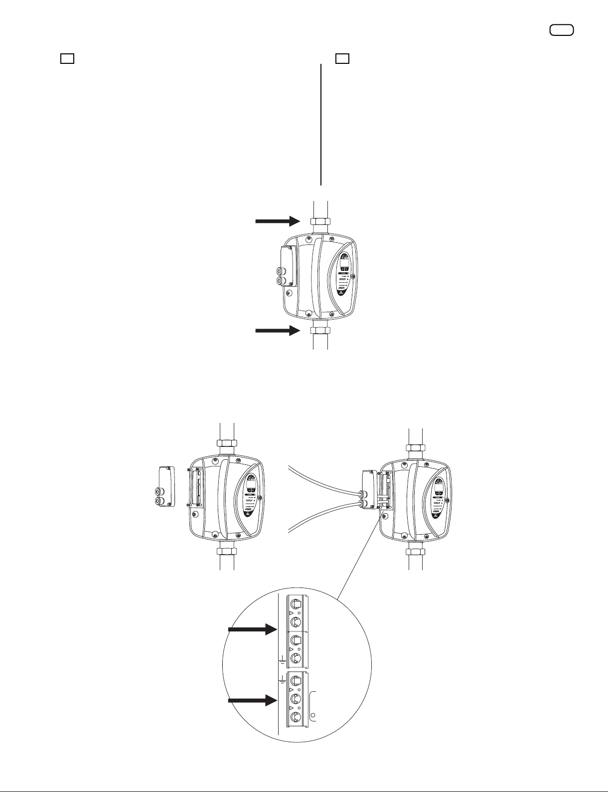
El WATER DRIVE esta provisto de 2 terminales (línea / bomba) las
cuales están disponibles al desatornillar la tapa de conexiones, pase
cada uno de los cables a través de los prensacables provistos en esta
tapa.
The device is provided with two terminals (line / pump)
accessible through a door with built-in cable glands, which
is connected to the device with screws.
Remove the door, exposing the terminal and passing the
cables in their cable glands:
- Conecte el cable de salida (pump) a la motobomba (2 fases y
erra). Ulice los terminales que se muestran como V y W para la
línea monofásica hacia la bomba.
- Connect the output cable (ground, single phase) use the
terminals V and W to connect the pump.
- Conecte el cable de entrada (alimentación-2 fases y erra) a través
de un interruptor de 2 polos de acuerdo a la máxima corriente de la
motobomba.
- Connect the input cable (phase, neutral, ground) to the
single-phase line through a circuit breaker sized according
to the pump rang.
A connuación un diagrama, a modo de ejemplo: Here aer a schema just for example:
(Modelo W-Drive2M2T)
El WATER DRIVE esta provisto de 2 terminales (línea / bomba) las
cuales están disponibles al desatornillar la tapa de conexiones, pase
cada uno de los cables a través de los prensacables provistos en esta
tapa.
The device is provided with two terminals (line / pump)
accessible through a door with built-in cable glands, which
is connected to the device with screws.
Remove the door, exposing the terminal and passing the
cables in their cable glands:
-Conecte el cable de salida (pump) a la motobomba (3 fases y
erra).
- Connect the output cable (ground, triple-phase, screen)
to the three-phase pump with (Δ) triangle conguraon
230 VAC.
-Conecte el cable de entrada (alimentación-3 fases y erra) a través
de un interruptor de 2 polos de acuerdo a la máxima corriente del
variador.
- Connect the input cable with three wires (phase, neutral
and ground) to the power supply through a single-phase
230VAC circuit breaker sized in funcon of the WATER
DRIVE rang.
A connuación un diagrama, a modo de ejemplo: Hereaer a schema just for example:
N
L
PI PI
N
L
PI PI
ES EN
12
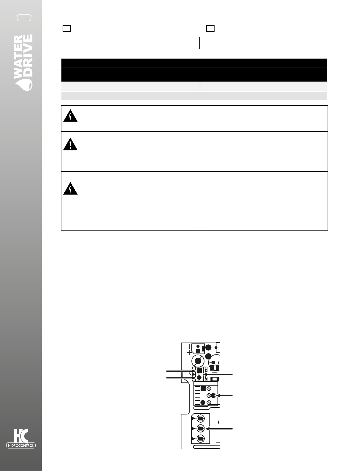
Todas las partes internas del WATER DRIVE están
energizadas, en caso de contacto puede sufrir
lesiones.
All internal parts of the drive are unde power supply. In
case of contact may sussit risk of death.
Toda instalación y/o mantenimiento deberá ser
efectuada por personal calicado, ulizando las
herramientas correctas y los equipos de seguridad
adecuados. En caso de algún fallo desenergice el
WATER DRIVE.
All installaon and maintenance work ,must
be performed by qualied sta using suitable
instruments! Sta must use suitable protecve
equipment. In the event of a fault, disconnect or
switch o the power supply.
Antes de realizar cualquier modicación en el
cableado del WATER DRIVE espere al menos 5
minutos para que el capacitor interno se descargue.
Before performing repairs on the drive wait at least 5
minutes to allow the capacitor to discharge.
Peligro de electrocución, se corre el riesgo de
sufrir lesiones severas en caso de no seguir esta
precaución.
Danger of electrocuon, burning or death if this
precauon is not observed.
Conexiones adicionales Additional connections
El WATER DRIVE está provisto de: The internal terminals are provided of:
-Terminal de entrada para la conexión de un otador
externo o un arranque remoto, si esta terminal está
programada, el WATER DRIVE permanecerá en stand by.
-Input for dry running oang or remote control. If this
input is enable, WATER DRIVE is set in stand by.
-Terminal de salida para: controlar una segunda bomba a
plena carga o acvar una alarma externa.
-Output relay to pilot a second pump at xed rate or to
acvate an external alarm.
- Conexión con otros WATER-DRIVE (modo multibombeo) -Connection with other WATER DRVE (multipumps mode)
La tapa de conexiones está diseñada para la perforación
y la inserción del cable para conexiones adicionales.
Para acvar estas funciones ingrese al menú avanzado
“extended menu”, en el parámetro 50 acve la operación
de la segunda bomba y en el parámetro 55 acve el uso de
otador.
The terminal cover is designed for drilling and inseron
of the cable for the addional links. (To set these
opons enter in extended menu.(param. 50 for 2nd
pump and 55 for oang).
Selección del cable de alimentación en
función a la distancia
Section power supply cable linked to
cable length.
MODELOS MM- MT
AWG Longitud máxima en metros - Maximum length in
meters
12 20
10 50
Flotador J11
J20
J10
FAN CAN
H L COM
RELAY RUN
NC C NO
REM.EN
1
1 3
J12
C74
+12
J11J20
J10
GND
ES EN

13
Conectar un switch otador externo How to connect a dry running oat
Es posible ulizar un switch otador externo para detener la bomba
al llegar a un nivel mínimo de agua. Para habilitar esta función:
You can use a oat switch stop the pump at the minimum water
level. To enable this funcon:
-Conecte el switch otador en la terminal “remote enable” (ver la
imagen de arriba).
-Connect the oatswitch on the terminals REMOTE ENABLE (see
picture above).
-Habilite la función de control remoto “remote control”
en el menú extendido (parámetro 55).
-Enable “remote control” funcon on extended menu paragraph
Extended Menu. (par.55)
Conectar una segunda bomba a plena carga
(ON/OFF):
How to connect a second pump ON/OFF (xed
rate)
Es posible ulizar la terminal “relay run” para controlar el arranque
de una segunda bomba a plena carga (ON/OFF).
-La terminal puede ser usada para controlar un contactor o un
relevador del arrancador que gobierna la bomba a plena carga.
-Para habilitar esta función vea los parámetros 50 y 51 del menú
extendido.
You can use the RELAY RUN to pilot a second pump ON/OFF.
-The relay can be used to operate a contactor or a relay, with
adequate power to drive the pump.
-Enable Booster funcon (see parameters 50 and 51 in the
Extended Menu).
Conguración Relay Relay Conguration
Es posible ulizar el relé (J10) en la placa madre como una señal
de alarma, de bomba acva, o para construir el sistema con una
segunda bomba en frecuencia ja. Las funciones pueden ser
habilitado por el menú ampliado (par.50).
It’s possible to use the relay (J10 ) on the mother board as a
warning signal, run pump, or to build boosng system with a
second pump at xed rate.The funcons can be enabled by the
extended menu (par.50).
Conguración Booster(Bomba ON/OFF) Booster Conguration (ON/OFF pump)
- Conecte el control de BOOSTER en el terminal J10 entre “C” y
“NO”. (Mira gura in párrafo “Conexiones adicionales”).
- Ajuste el parámetro 50: “Conguraon.Relay” = “BO”
- Ajuste el parámetro 51 “Inc Pres Booster” para aumentar el
valor de la presión (estandard = 0,2 bar). Este valor determina el
aumento en la presión del sistema requerida después de arranque
la bomba ON / OFF.
- Connect the control of booster on J10 between “C” and “NO”.
- Set parameter 50 : ”Conguraon Relay” = “BO”
- Set the parameter 51 “Inc Pres Booster” the value of pressure
rise (default = 0.2 bar). This value determines the increase of the
system pressure required aer the starng of the pump ON / OFF.
ES EN
Booster Operation Booster Operation
Modalidad de alimentación de la segunda bomba ON / OFF: How to start second pump ON / OFF:
Cada vez que NO se alanza la presión del sistema y la frecuencia del
inversor ha llegado a la frecuencia máxima de funcionamiento de
la bomba (es.50Hz/60Hz), se acciona el comando para arrancar la
bomba ON / OFF.
Con la puesta en marcha de la segunda bomba se incrementa la
presión del sistema de un valor igual a la jada en el parámetro 51
“Inc Pres Booster” (por defecto 0,2 bar). Este parámetro determina
el aumento en la presión del sistema para evitar la oscilación. En
caso de necesidad se puede aumentar hasta un máximo de 1,5 bar
(por defecto = 0,2 bar)
If the rst pump cannot reach pressure system and the frequency is
at the maximum working value (es.50Hz/60Hz), the drive switch on
the command to start the second pump ON / OFF.
As soon the second pump is started, the drive increase the system
pressure value by an amount equal to the parameter 51 “Inc Pres
Booster” (default 0.2bar [2.9psi]). This parameter determines the
increase of the system pressure to avoid oscillaon. In case of need
can be increased up to a maximum of 1.5 bar [21.75 psi] (default =
0.2 bar [2.9psi]).
Modo de parada de la bomba Segunda ON / OFF: How to stop the second pump ON / OFF:
El parámetro que desacvación a la segunda bomba es: The parameter that switches o the control for the second pump is:
- parámetro 64 “umbral mínimo” (de fábrica =60%) -parameter 64 “MinTresholdPar” (default = 50%)
Cuando el porcentaje de la potencia suministrada por el variador
está por debajo del umbral mínimo (par.64) y la presión medida
es mayor que la presión del sistema, a connuación el comando
desacva la segunda bomba.
When the percentage of power is lower than the threshold and the
measured pressure is higher than the system pressure, then the
drive switches o the second pump.
Parámetro 47 “Potencia del motor” = 1000 was
parámetro 64 “Umbral Mínimo” = 50%
parámetro 72 “Press. del sistema” = 2.5 bar
Parameter 47 “Motor Power” = 1000 was
parameter 64 “MinTresholdPar” = 50%
parameter 72 “System Pressure” = 2.5 bar [36.26 psi]
Teniendo en cuenta los datos anteriores, la potencia para desacvar
la segunda bomba es ‘igual a 50% de 1000 was osea 500 was.
Si la presión medida es “mayor o igual a 2.5 bar y la potencia
medida es menor a 500 was, está, apaga la segunda bomba.
The power value to switch o the second pump is equal to 50% of
1000 was then: 500 was. So that if pressure is greater or equal to
2.5 bar [36.26 psi] and power is less than 500 wa the drive switch
o the second pump.
N.B. El Booster Conguración se acva sólo cuando el modo
de funcionamiento del inverter es AUTOMÁTICO (consulte el
parámetro 28 en el menú ampliado)
N.B. The Booster conguraon is only acve when the operang
mode of the inverter is AUTOMATIC (see parameter 28 in the
Extended Menu)
14
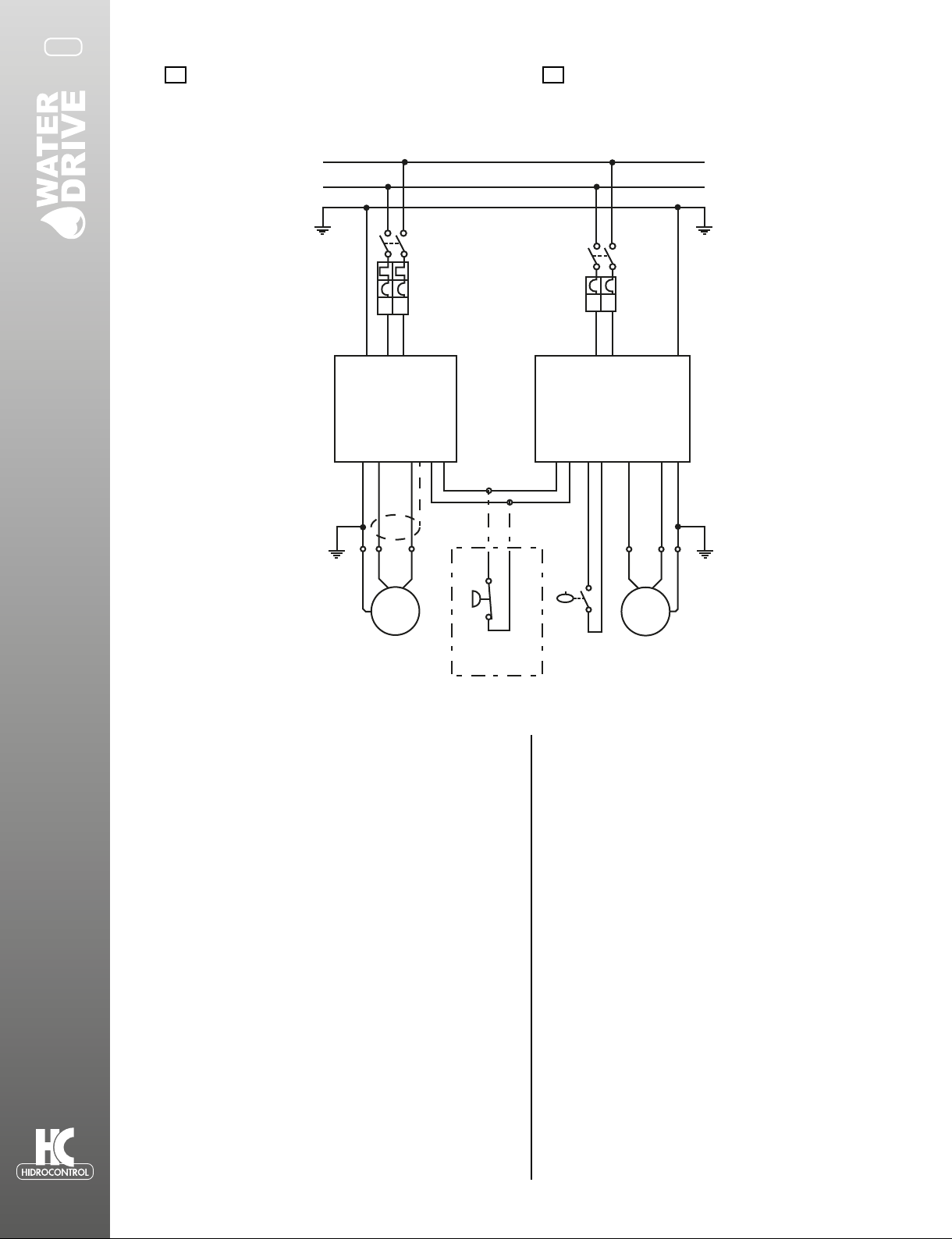
Id
PE
N
L
Id Id
INTERRUPTOR
AUXILIAR
DE PRESIÓN
BOMBA
BOMBA
Id
PANEL DE CONTROL
Ejemplo de conexión para el Modo Booster
(bomba ON / OFF - versión MM / MT)
Connection example for Mode Booster
(pump ON / OFF – MM/MT version)
ES EN
En caso de mantenimiento
del Variador se puede
conector un presostato
auxiliar que permite
garanzar la connuidad del
servicio en el sistema con la
segunda bomba.
Se recomiendo preveer
el uso de una tanque de
expancion adecuado para
esta apicacion.
Atencion: El
presostatoauxiliar no debe
ser conectado cuando se usa
el variador.
In case of
maintenance of the
inverter, an auxiliary
pressure switch can
be connected to
guarantee connuity
of service to the
system with the on-
o pump.
It is advisable to
provide in this
case the use of
an expansion
tank correctly
dimensioned.
Beware the auxiliary
switch should not be
connected when the
inverter.
Conguración Multibomba Multipump Conguration
Es posible conectar WATER- DRIVE en conguración mulbomba
(sólo modelo AVANCED) compuesto de un variador Maestro que
controla hasta 7 variadores esclavos.
It’s possible to connect ePower in mulpumps
conguraon (ADVANCED model only) composed from
an inverter Master that can drive 7 inverter Slave.
Para habilitar la conguración mulbomba es necesario: To enable mupump mode is needed:
- quitar la tapa y abra uno de los agujeros colocados en la cubierta.
Ulizar un prensacable adecuado sobre el cable para la conexión.
Uliza el terminal J20 terminal como en “Ejemplo de conexión modo
Maestro/Esclavo”
- Congure el parámetro 28 “Próximo OpMode” con el valor “MP”:
mulbomba.
- Congure el parámetro 4 “Cong red ID” con un número entre 0
y 7. El inverter con el valor numérico más bajo es el del Master del
grupo.
- Establecer el parámetro 47 “potencia nominal” con el valor de
la potencia nominal de la bomba (P1). (sección Menú extendido
parámetro 47). En el caso que en la placa de la bomba solo se
encuentra la potencia de salida P2, insertar como potencia nominal
el valor del cálculo P2/0.7. Ambos valores de potencia (P1 y P2) de la
unidad de medida se expresa en vaos.
- Después de salir del menú extendido, la unidad principal muestra
“MA” y la unidad Slave muestra “Ux” (donde x es el número asignado
al variador con el parámetro 4).
- Remove the lid and open one of the holes located in
the area of pre-drilling. Apply a cable gland of adequate
size for the type of cable used for the connecon
between Master and Slave and connect them using the
terminals J20 see “Connecon between Master/Slave”.
- Set the parameter 28 “Next OpMpde” with the value
“MP”: Mulpump.
- Set the parameter 4 “Net Cong ID” with a number
between 0 and 7. The inverter with lowest numerical
value is the Master of the group.
- Set the parameter N. 47 “Motor Power” with the
nominal power value of the pump (P1). (See parameter
47 in Extended Menu secon). If in the pump is shown
only the useful power P2, the nominal power is given
by P2/0.7. For both the power values (P1 and P2), the
unit of measurement is expressed in was.
- Aer exing from extended menu, the Master unit
displays “MA”, while the Slave unit displays “Ux”
(where x is the number assigned to the inverter with
parameter 4).

15
FLOATING
OUT RELAY
PUMP
J20
WD1
WD2
WD8
FAN CAN
H L COM
RELAY RUN
NC C NO
REM.EN
1
1 3
J12
C74
+12
J11J20
J10 GND
UV
U
W
J1
NL
J20
FAN CAN
HL COM
RELAY RUN
NC C NO
REM.EN
1
1 3
J12
C74
+12
J11J20
J10 GND
UV
U
W
J1
NL
J20
FAN CAN
H L COM
RELAY RUN
NC C NO
REM.EN
1
1 3
J12
C74
+12
J11J20
J10 GND
UV
U
W
J1
NL
Ejemplo de conexión Mulbomba Connecon MULTIPUMPS
Es posible ulizar sólo un otador para controlar el grupo en el
modo mulbombas:
It’s possible to use only one oatswitch to control the mulpump group:
Menú Software Menu
Ulice los botones de “+” y — para posicionarte en el parámetro
deseado, de acuerdo a la siguiente tabla. Para cambiar el parámetro
seleccionado, presiona el botón de SAVE/DISPLAY por 5 segundos
hasta que la luz encienda en color rojo. Cambia el valor del parámetro
ulizando los botones de “+” y - . Guarde eI valor deseado presionando
el botón de SAVE/DISPLAY por 5 segundos. Se recomienda consultar la
siguiente sección para solucionar problemas.
Use the + and – to select the desired parameter, among those listed in
the table, and read its value.
To change the selected parameter, press the SAVE / DISPLAY buon for
5 seconds, unl the LED turns red. Change the value of the parameter
using the + and -.
Save the value by pressing for 5 seconds, the buon SAVE / DISPLAY.
You should consult also the next secon for troubleshoong.
Param DESCRIPCIÓN Descripon
PRESIÓN Muestra la presión de la red. Displays the in pipe pressure.
Se establece la presión de trabajo del sistema. Sets the required system pressure
PRESIÓN DE
ARRANQUE
Muestra la presión de arranque. Displays the restart pressure.
Se establece la presión de re-arranque del sistema.* Sets the required restart pressure
FRECUENCIA
Muestra la frecuencia a la cual gira la bomba. Displays the instant pump frequency.
Valor máximo de frecuencia del motor (no es posible
modicar este valor desde este menú).
Max value set for the frequency (not changeable in this
menu)
CORRIENTE Muestra la corriente consumida por la bomba. Displays the current absorbed by the pump.
Se establece la corriente máxima de la bomba. Set the max rms value of the phase current
La presión de arranque es denida por el WATER DRIVE The restart pressure is calculated from WATER DRIVE .
Presión de arranque = Presión de trabajo x 0.8. Press. Restart = Press. System x 0.8.
Para modicarla, establezca el nuevo valor después de ajustar la
presión de trabajo del sistema.
To change it, please set the new value aer seng the system
pressure.

16
Conguración Conguration:
Rere la tapa y perfore los oricios marcados en la tapa de
conexiones. Ulice un cable de tamaño adecuado para la
conexión entre maestro y esclavo ulizando las terminales J10
y J11.
• Ajuste el parámetro No.50 "Congurar el Relay " con el valor
" MA" para el variador maestro y "SL" para el variador esclavo.
• Ajuste el parámetro No. 47 " Potencia del motor" con el valor
de la potencia nominal de la bomba
(valor considerado en was).
•Ajuste el parámetro No. 64 " Frecuencia mínima BOOSTER"
con el valor umbral en % de la potencia absorbida. El variador
se apaga si la potencia absorbida de la unidad secundaria está
por debajo del umbral.
Remove the lid and open one of the holes located in the area
of pre-drilling. Apply a cable gland of adequate size for the
type of cable used for the connecon between Master and
Slave and connect them using the terminals J10 and J11.
• Set the parameter N. 50 “Conguraon Relay” with the value
"MA" for the Master unit and "SL" for the Slave unit. (See
parameter 50 in Extended Menu secon)
• Set the parameter N. 47 “Motor Power” with the nominal
power value of the pump (P1). (See parameter 47 in Extended
Menu secon). If in the pump is shown only the useful power
P2, the nominal power is given by P2/0.7. For both the power
values (P1 and P
• Set the parameter N. 64 “Minimum threshold” with the
threshold in % of the absorbed power. The inverter is turned
o if the absorbed power of the Slave unit is below the
threshold (See parameter 64 in Extended Menu secon).
Nota: Los parámetros que intervienen en la conguración del
modo Maestro / Esclavo deben establecerse en los mismos
valores para ambos inversores, excepto el parámetro 50 que
determina si el variador será maestro o esclavo.
NB: The parallel mode is not a system of passing parameters
from one inverter to another. The parameters involved in the
conguraon of the Master/Slave mode must be set to the
same values for both inverters, except Par.50 that determines
whether the unit must be Master or Slave.
Calibración del sensor de presión Sensor calibration
Es muy importante que los dos variadores (Maestro y Esclavo)
registren el mismo valor de la presión medida. Con el n de
obtener el máximo rendimiento de la conguración maestro/
esclavo, por tanto es necesario prestar atención a la calibración
del sensor de presión.
En caso de que sea complejo para alinear las presiones
medidas, se puede desalinear el valor de la presión del sistema
para compensar el error.
It is important that both units have the same value of the
measured pressure. In order to obtain maximum performance
from the Master/Slave conguraon is therefore necessary to
pay aenon to the calibraon of the pressure sensor.
In case it is complex to align the measured pressures, it is
also possible to misalign the value of system pressure to
compensate the error.
Por ejemplo, si la presión medida por el variador maestro es
50 psi y la presión medida por el variador esclavo es 52 psi ( 2
psi de diferencia entre los dos variadores), puede congurar la
presión del sistema de la siguiente manera:
Variador Maestro PRESIÓN DE TRABAJO = 55 psi
Variador Esclavo PRESIÓN DE TRABAJO = 57 psi
( valor obtenido sumando la presión de trabajo del variador
Maestro y la diferencia de presión entre los variadores maestro
y esclavo).
For example, if the pressure measured by the MASTER = 2 bar
and the pressure measured by the
SLAVE = 2.2 bar (0.2 bar dierence between the two units),
you can set the system pressure as follows:
System pressure MASTER = 2.5 bar
System pressure SLAVE = 2.7 bar (value obtained by: MASTER
System pressure + pressure dierence measured between
Master and Slave).
Comunicación Communication
La comunicación le permirá mantener las dos
caracteríscas siguientes:
The communicaon allows to support the two following
features:
• Acvación de un variador esclavo
• Rotación Maestro / Esclavo
• Acvaon Slave unit
• Rotaon Master/Slave
El variador esclavo se acva sólo por el variador
Maestro. La rotación del variador Maestro / Esclavo permite
distribuir la carga de trabajo entre los dos variadores.
The Slave is acvated only by the Master. The rotaon of
Master/Slave allows to distribute the workload between the
two units.
ES EN
Conexión hidráulica Hydraulic Connection
WATER DRIVE puede ser instalado en cualquier posición. WATER DRIVE can be installed in any posion.
Precauciones: Warnings:
- Asegúrese de que la bomba esté pefectamente cebada, antes
de instalar el WATER DRIVE.
- Instale el WATER DRIVE cerca de la bomba, si es directa la
instalación verique no existan vibraciones que afecten al
WATER DRIVE.
- No ulice una tubería de descarga menor al diámetro del
WATER DRIVE.
- Evite lugares húmedos.
- Instale un tanque precargado para proteger el equipo contra
golpes de presión y connuos arranques con demandas
mínimas.
- Make sure pump is perfectly primed, before installing
WATER DRIVE.
- Install WATER DRIVE near the pump; if installed directly on
the pump, verify that there are no harmful vibraons.
- Use tube diameter not less than those of WATER DRIVE
aacks.
- Avoid places where is possible precence of condensaon.
- Install an expansion tank to protect The product against
water hammer and to avoid connuous restarng in presence
of small losses.
17
ES EN
Notas de instalación Installation Notes
- Se recomienda instalar una llave de pruebas. - Recommended to install a tap sampling.
- Insertar ltros en la red hidráulica para proteger que
sólidos en el agua dañen tanto a la motobomba como al
WATER DRIVE (Nota 1).
- Insert a cartridge lter to protect both the system that the
device from impuries, always present in the water (Note 1).
- Es necesario ulizar válvulas check en la red hidráulica de
acuerdo a la distancia y las caracteríscas de la red.
- The inclusion of an external check valve is mandatory.
- Para facilitar el mantenimiento instale el WATER DRIVE
ulizando tuercas unión.
- For easy maintenance, mount the drive using a 3-piece
union ngs
- Instale una válvula de compuerta antes de la conexión al
tanque de precarga para facilitar su mantenimiento.
- Install a tap near the drive to facilitate the control of the
drive.
-Install a gate valve in series with the expansion tank for easy
maintenance.
Nota 1: El agua en ocasiones contiene restos de sólidos, por tal motivo es necesario colocar filtros para evitar que estos entren en la tubería y ocasionen daños en el sistema de presión. Note 1 : The water always contains sand, iron, debris; such impurities should not enter the hydraulic system because they cause corrosion of pipes, damaging the equipment connected to plumbing.
Water filtration for domestic use is required under the UNI-CTI 8065 and by decree of the Ministry of Health of 12.21.1990.
Installing a filter is not an option but a provision.
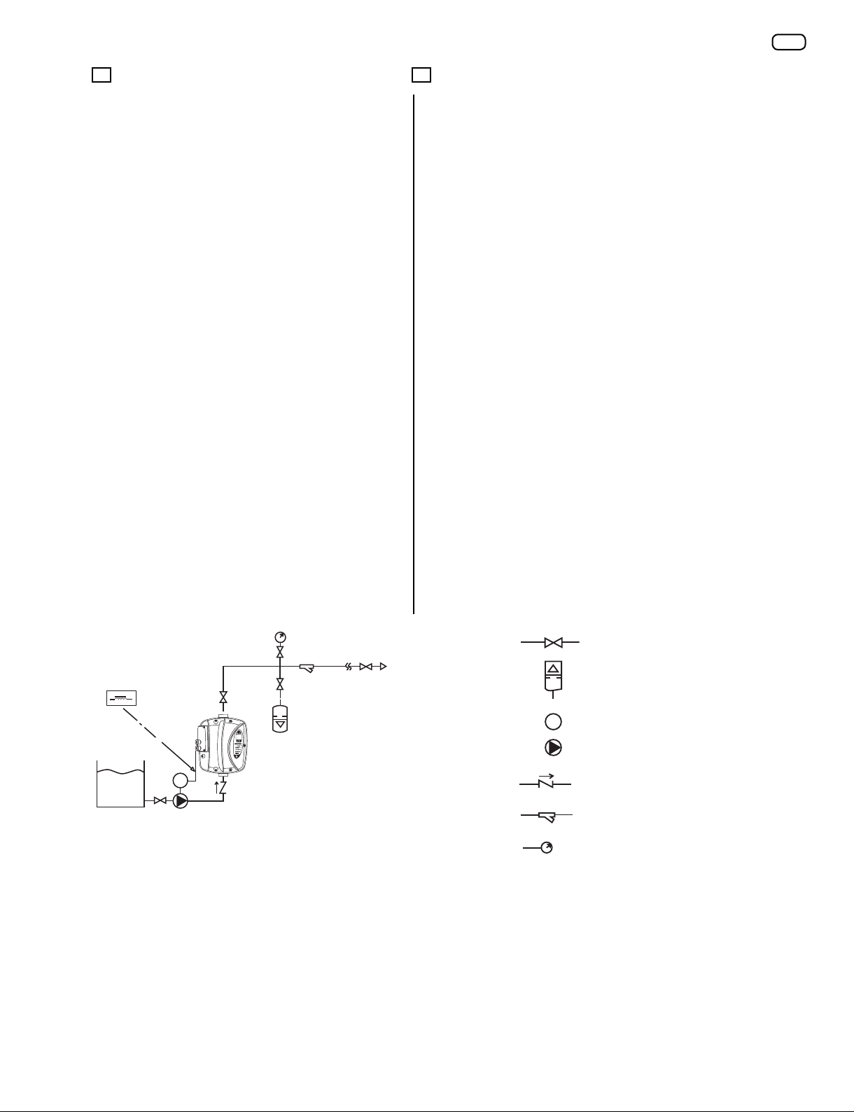
Diagrama de instalación hidráulica Hereafter a typical system diagram with
surface pump suction head
FILTRO
P
M
P
M
FILTRO
P
M
P
M
Válvula de
compuerta
Tanque de
expansión
Motobomba
Válvula check
Filtro
Manómetro
Shut of Valve
Expansion tank
Motor/pump
Non return valve
Hidraulic Filter
Pressure gauge
Ejemplo del dimensionamiento del tanque de acuerdo a la
bomba. Bomba de 100LPM, tanque precargado de 10L (10% del
máximo ujo de la bomba).
Eg. Size, in liters per minute according to the pump:
Pump 100lt/min expansion tank from 10lt/min (10% of
the maximum ow of the pump).
La presión de precarga del tanque debe ser de un 80% de la
presión de trabajo del sistema.
Ejemplo:
Presión del sistema= 43 psi
Presión de arranque= 37 psi
Valor de precarga del tanque= (43 x 0.8)= 34 psi
Preload value of the expansion tank should be about 0.8 x
value of system pressure.
Eg.
System pressure = 3 bar
Restart pressure = 2.6 bar
value of precharge = (0.8 x 3) = 2.4 bar
Si la presión de arranque es programada a más de 14 psi sobre
la presión de trabajo, entonces establezca el 80% de la presión
de arranque.
If the restart pressure is at least 1 bar lower than the system
pressure, then the precharge value of the expansion tank
should be about 0.8 x pressure value of restart pressure.
Ejemplo.
Presión del sistema= 43 psi
Presión de arranque= 29 psi
Valor de precarga del tanque= (29 x 0.8)= 23.2 psi
Eg.
System pressure = 3 bar
Restart pressure = 2 bar
value of precharge = (0.8 x 2) = 1.6 bar

18
ES EN
SOLUCIÓN DE PROBLEMAS Y
MANTENIMIENTO TROUBLESHOOTING
AND MAINTENANCE
El WATER DRIVE ofrece protecciones a la motobomba contra
cualquiera de las fallas más comunes en una instalación
hidráulica. Para asegurar el suministro de agua en la instalación
el WATER DRIVE realice restablecimientos automácos y
programables. El Display del WATER DRIVE muestra el mensaje
para idencar el po de falla.
The WATER DRIVE provides pump protecon
from any type of common problems and
to safeguard the water supply the drive
aempts automac restarts. The display
shows a message to idenfy the type of
fault.
CÓDIGO
CODE MENSAJE
MESSAGE FALLA SOLUCIÓN FAULT SOLUTION
00 Corto Circuito
ShortC. f-f
Se ha detectado un corto
circuito entre fases o fase
y erra.
Se harán 5 intentos
de restablecimiento
automáco, después
es necesario un
restablecimiento manual.
Idenque el corto
circuito.
Compruebe el consumo
de corriente de la
motobomba.
Desconecte el voltaje del
WATER DRIVE, espere que
se apague el Display y
conecte de nuevo.
Phase-Phase or
Phase-Ground short
circuit found.
5 Automac
restarts and then a
permanent locked
status.
Remove the short
circuit.
Check the correct
motor absorpon.
Disconnect the power
supply.
Wait for the display to
switch o.
Restore the power
supply.
01
Sobre corriente
Imax Fault Sobrecorriente detectada
en la bomba.
Compruebe el valor
de corriente medido
en el parámetro 36.
Y establezca un valor
apropiado como máxima
corriente en el parámetro
49.
Compruebe que no exista
bloqueo o fricción en los
impulsores.
Over current
detected in the
pump.
Check current
measurement output
at parameter 36
“LoadCurrent “ and
set the proper value
of max. current at
parameter 49.
Verify that the pump
is used under the
condions prescribed
by its manufacturer.
Make sure that there
are no condions of
fricon or locking of
the impeller.
02 Bajo voltaje.
Low Voltage.
El voltaje de alimentación
es sensado por debajo del
rango permido (menor a
170 VCA).
El restablecimiento es
automáco cuando el
voltaje alcanza los valores
correctos.
Corrobore que el voltaje
del sistema este dentro
de los valores permidos
por el WATER DRIVE.
Power voltage
measured is too low
(170 VAC vers MM/
MT).
The reset is
automac when the
voltage returns to
the correct values.
Check the electric
system and reset the
values to within the
range prescribed for
the WATER DRIVE.
03
Alto voltaje.
High voltage.
El voltaje de alimentación
es más alto de lo
permido (mayor a 270
VCA)
El restablecimiento es
automáco cuando el
voltaje alcanza los valores
correctos.
Corrobore que el voltaje
del sistema este dentro
de los valores del WATER
DRIVE.
Power voltage
measured is too high
(270 VAC vers. MM/
MT).
The reset is
automac when the
voltage returns to
the correct value.
Check the wiring
system and set the
values in the range
prescribed for the
WATER DRIVE.
Check for the presence
of air inside the pump
and if necessary
eliminate it.

19
CÓDIGO
CODE MENSAJE
MESSAGE FALLA SOLUCIÓN FAULT SOLUTION
ES EN
04
Alta
temperatura
del líquido.
High Temp.
La temperatura del líquido
es mayor a 75 °C.
Restablecimiento
automáco si la
temperatura < 60 °C.
Conrme que la
temperatura del agua
está dentro de los
parámetros permidos
por el WATER DRIVE.
Water Temp>75 °C.
Automac reset if
Temp.< 60 °C:
Check water
temperature is within
the values indicated
in the product
specicaons.
Check and restore the
correct pump priming
acon.
05
Bloqueo por
cortocircuito.
Short
Circ.Block
El WATER DRIVE está
bloqueado. Hará 10
intentos por reiniciar,
buscando que el corto
circuito a erra o entre
fases se ha eliminado. De
no ser así es necesario
reiniciar manualmente.
Para remover el estatus
de bloqueo, coloque
en cero el número de
cortocircuitos en el
parámetro 65 “Total
de cortocircuitos
detectados”. Sí el
problema persiste
intente reinciar el WATER
DRIVE desconectando la
motobomba.
The drive is in lock
status aer 10 reset
aempts made
following short
circuit between
phase and phase
and phase-earth on
the electro-pump.
To remove lock
status set to zero the
number of shortcircuit
parameter 65 “Tot.
ShortC.Done “
If the problem persists
try to reset the drive
unplugging the pump
06 Pico de
corriente.
El WATER DRIVE ha
detecto una excesiva
corriente.
Compruebe que la
motobomba sea usada
de acuerdo a su diseño y
que no exista bloqueo o
fricción en los impulsores.
The drive has
measured an
excessive current.
Verify that the pump
is used under the
condions prescribed
by its manufacturer.
Make sure that there
are no condions of
fricon or locking of
the impeller.
07
Motobomba
desconectada.
Motor
unconnected
La motobomba no esta
conectada al WATER
DRIVE.
Corrobore que la bomba
está conectada al WATER
DRIVE.
The pump isn’t
connected to the
inverter.
Check that the power
output cable from the
inverter is connected
to the pump.
10 Sin líquido.
No water.
Falta de líquido detectada,
restablecimiento
automáco de fábrica= 5
intentos cada 5 minutos;
sí no se detecta líquido en
estos intentos, se harán
24 intentos más cada 50
minutos, si después de
esto no se ha corregido la
falta de líquido, el sistema
requiere reinicio manual.
Verique:
- La presencia de líquido.
- Que la motobomba
fue cebada de forma
correcta.
- Que el ltro no está
bloqueado.
- Desenergice la
alimentación del voltaje.
Espere a que se apague
el Display y energice de
nuevo.
Lack of water found.
Automac reset
set in factory for
5 reset aempts
every 5 minutes;
if unsuccessful
the reset is again
aempted every
50 minutes for 24
mes.
Aer which the
system remains in a
state of permanent
blockage.
Check for water
presence.
Reset the correct pump
priming funcon.
Check that the lter is
not blocked.
Disconnect the power
supply.
Wait for the display to
switch o. Re-connect
power supply.
11
Presión
insuciente.
Insu. Pres
La presión medida está
por debajo del mínimo
valor permido (de
fábrica 0.8 bar /11
psi). Restablecimiento
automáco, 1 intento
cada 5 minutos, si no
se consigue restablecer
se harán 24 intentos,
un intento cada 50
minutos. Después de
esto el sistema requiere
restablecimiento manual.
Corrobore:
-Que no existan fugas en
la red hidráulica.
-El correcto
dimensionamiento del
sistema.
-Una vez eliminada la
falla, desenergice el
WATER DRIVE, espere
a que se desenergice
el Display y energice
nuevamente.
The pressure
measured is under
the minum set value
(default 0.8 bar).
Automac reset
set in the factory
for 1 reset aempt
every 5 minutes if
unsuccessful the
reset operaon is
aempted again
every 50 minutes
for 24 mes. Aer
which the system
is permanently
blocked.
Check that there is no
major leakage on the
system.
Check the correct
dimensions of the
electro-pump.
On eliminang the
causes disconnect the
power supply.
Wait for the display to
switch o.
Restore power supply.

20
12
Fallo del sensor
de presión.
Press sensor
fault.
Se ha detectado fallo en el
sensor de presión.
Contacte a su
distribuidor.
Detected a fault in
the pressure sensor.
Contact aer selling
service.
13 Golpe de ariete.
Water Hammer.
El sistema ha detectado
una sobrepresión
mayor a 2 veces la
presión de trabajo. El
restablecimiento es
automáco. El variador
requiere restablecimiento
manual después de 5
intentos.
Vericar el correcto
dimensionamiento del
tanque precargado.
The system detected
an overrun of more
than 2 mes the
pressure set.
The reset is
automac.
The drive is blocked
if the number of
automac restarts is
over 5.
Verify the correct
funconing of
expansion tank.
15
Protección de la
bomba
Pump
protecon
La bomba ha
estado funcionando
connuamente durante el
empo establecido en el
parámetro 40
Compruebe que no
existan fugas en el
sistema
The pump has
been in operaon
connuosly for
the me set in
parameter 40
Check the leaks of the
system
MA Maestro EL variador esta
congurado como Maestro
EL mensaje "MA" puede
visualizarse cuando se
uliza el variador en modo
Mulbomba
The inverter is
congured like
Master
The message "MA" is
displayed when the
inverter is used in
mulpump mode.
SL Esclavo El variador está
congurado como Esclavo
The inverter is
congured like
Slave
CB CANBUS
El Modo Mulbomba
uliza el protocolo de
comunicación CANBUS.
La pantalla muestra "CB"
cuando un intercambio de
datos está presente entre
los inverter de un grupo.
Mulpump mode uses
CANBUS communicaon
protocol . The display
shows "CB" when a data
exchange is present
between the inverters in
a group.
ID
ERROR DE
IDENTIFICACIÓN
ID ERROR
En el modo Mulbomba
el usuario asigna un
valor numérico (ID) que
idenca el inverter en un
grupo. El mensaje indica
que el grupo son inverter
con el mismo idencador
numérico.
Para eliminar el error ene
que cambiar en el menú
avanzado, el parámetro 4
"Cong. Red ID" y asigne
el inversor un nuevo valor
numérico entre 0 y 7
In Mulpump mode
the user assigns
a numerical value
(ID) that idenes
the inverter in a
group. The message
indicates that in the
group are inverters
with the same
numerical idener.
To remove the error
you need to change
from extended menu,
parameter 4 "Net Cong.
ID" and assign to inverter
a new numeric value
between 0 and 7.
Ux Unidad "x" Unit
"x"
Idenca los Slave en
modo mulbomba. "x" es
el valor numérico asignado
al parámetro 4 "Cong.
Red ID”
Idenes the slave
unit in mulpump
mode. "x" is the
numerical value
assigned to the
slave in parameter
4 "Net Cong. ID "
Fs Fuera servicio
Out of service
El mensaje aparece en
el modo mulbomba.
El inverter terminó los
reinicios automácos
Idencar la causa de
la anomalía y reinicie el
inversor
The message
is displayed in
mulpump mode.
The inverter
nished the
automac restarts.
Find the cause of the
fault and restart the
inverter
CÓDIGO
CODE MENSAJE
MESSAGE FALLA SOLUCIÓN FAULT SOLUTION
This manual suits for next models
1
Table of contents
Other HIDROCONTROL DC Drive manuals


