manuals.online logo
Brands
  1. Home
  2. •
  3. Brands
  4. •
  5. Mitsubishi Electric
  6. •
  7. DC Drive
  8. •
  9. Mitsubishi Electric FR-A 500 User manual

Mitsubishi Electric FR-A 500 User manual

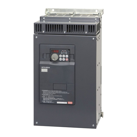
FR-A 500
Frequency Inverter
Instruction Manual
FR-A5NP
Profibus DP Communications
Option Unit
71065
VC7BNA00010-C
MITSUBISHI ELECTRIC
Art.No.:
2001 03 02
MITSUBISHI ELECTRIC
INDUSTRIAL AUTOMATION
2
Windows, DOS and other product names may be trademarks or registered trademarks of
their respective companies.
FR-A5NP Profibus DP
Communications Option Unit
3
NOTES, CAUTIONS AND WARNINGS
NOTE: Notes are used to provide additional detail about a procedure. The
Note will always precede the text that the Note refers to.
CAUTION: Cautions provide additional detail where failure to ob-
serve the Caution may result in damage to the equip-
ment or slight injury to the user.
WARNING: Warning provide additional information, where failure to
observe the Warning may result in death or severe injury
SAFETY INSTRUCTION
1. Electric Shock Prevention
WARNING:  Do not open or remove the front cover while the Variable
Frequency Drive is running. You may get an electrical shock.
 When necessary to perform inspections or when wiring the
unit, switch power off and wait at least 10 minutes and until
the bus charge light is off. Check for residual voltage.
 Do not attempt to inspect or wire this unit unless fully com-
petent to perform the work.
 Be sure hands are dry before operating any switches.
 Be sure cables do not have scratches, excessive stress,
heavy loads or pinching to prevent electrical shock
2. Injury Prevention
CAUTION:  Be sure all connections are in accordance with instructions
in this manual
 Check that cables are properly connected before turning
equipment on.
 After turning equipment off, wait at least 10 minutes and
until the bus charge light is off before removing cover. With
cover removed, charged components may be exposed.
4
3. Additional Cautions and Warnings
CAUTION:  Do not install the option unit if it is damaged or has parts
missing
 Check that option unit is securely fastened to the variable
frequency drive.
 Do not stand or rest heavy objects on top of unit.
 Do not allow metal fragments, conductive bodies, oil or other
flammable substance to enter the variable frequency drive.
 Before starting operation, confirm and adjust the parameters.
Failure to do so may cause the machines to make unex-
pected motions.
 When parameter clear or all parameter clear is performed,
each parameter returns to the factory setting. Reset the
required parameters before starting operation
 For prevention of damage caused by static buildup, touch a
nearby metal object to remove static from your body.
 Dispose of this product as general industrial waste.
WARNING:  Do not modify this equipment
FR-A5NP Profibus DP
Communications Option Unit
5
TABLE OF CONTENTS
Page
1. INTRODUCTION .............................................................................. 7
2. INSTALLATION ................................................................................ 9
2.1. PRE-INSTALLATION CHECKS .................................................. 9
2.2. MOUNTING PROCEDURE ........................................................ 9
2.3. CONNECTING TO THE NETWORK ........................................ 15
2.4. LED STATUS INDICATOR ....................................................... 16
2.5. INSTALLING MEAU0865.GSD ................................................. 16
3. OPERATION ................................................................................... 17
3.1. OPERATING MODES ............................................................. 17
3.2. SELECTING THE OPERATING MODE .................................... 17
3.3. FUNCTIONS AVAILABLE IN THE OPERATING MODES ......... 18
3.4. INPUT FROM PROFIBUS TO VFD.......................................... 18
3.5. OUTPUT FROM VFD TO PROFIBUS ...................................... 19
3.6. OPERATION WHEN AN ALARM OCCURS ............................. 20
4. PROFIBUS DEVICE DATA ............................................................. 21
5. A500(L) VFD PROFIBUS DATA WORD DEFINITION.................... 23
5.1. WORD 1 (PKE) ....................................................................... 25
5.2. WORD 2 (IND) ........................................................................ 26
5.3. WORD 3 ................................................................................. 26
5.4. WORD 4 (PWE2) .................................................................... 26
5.5. WORD 5 (ZSW1) .................................................................... 27
5.6. WORD 6 ................................................................................. 27
6. PARAMETER DEFINITIONS .......................................................... 28
6.1. IND = 0, REAL-TIME MONITOR AREA ................................... 28
6.2. IND = 1, SYSTEM ENVIRONMENT VARIABLE AREA............ 29
6.2.1. IND = 0100H, SEV_I, SEV INTERFACE ....................... 29
6.2.2. IND = 0101H, SEV_II, ALARM HISTORY ..................... 30
6.3. IND = 2, NORMAL PARAMETER AREA ................................. 31
6.4. IND = 3, 900F PARAMETER AREA ........................................ 38
6
TABLE OF CONTENTS (Continued)
Page
6.5. IND = 4, 900% PARAMETER AREA ....................................... 38
6.6. IND = 1, SPECIAL AREA ....................................................... 39
6.7. IND = 8, TIME/PROG SETTINGS T COMPONENTS ............... 40
6.8. IND = 7, TIME/PROG SETTINGS D COMPONENTS ............... 41
7. TROUBLESHOOTING ................................................................... 42
8. REFERENCES .............................................................................. 43
9. SPECIFICATIONS .......................................................................... 44
APPENDIX A. INSTRUCTION FOR MEAU0865.GS........................... 45
Appendix B. Commonly Used Profibus DP Commands .................... 46
Appendix C. Network Communication Coordination ........................ 58
Appendix D. Other Option Specific Parameters ................................ 60
FR-A5NP Profibus DP
Communications Option Unit
7
1. INTRODUCTION
GENERAL
The purpose of this manual is to provide general information, installation,
and operation procedures for the FR-A5NP Profibus DP option, used with
the FR-A500(L) Variable Frequency Drive, herein after referred to as the
VFD. Read this manual completely before installing, operating or servicing
the option unit.
This manual is intended for use by qualified personnel. Installation should
only be performed by qualified personnel. You must be able to operate and
program serial devices to use the equipment.
This option unit lets you connect an FR-A500(L) series VFD to a network
adhering to the Profibus DP communications protocol. Profibus DP is the
performance-optimized version of Profibus for time-critical operations.
Illustrations provided in this manual may have covers or safety guards re-
moved to provide a clear view. Before starting operation of the product be sure
to install covers and guards into the original position.
The following is a list of important features for the option unit
 Data Rates to 12,000,000 bps.
 Up to 126 stations supported on a single network
 Network access to all VFD parameters.
 Certified by Profibus Nutzer Organization in July 1998
 Designed and assembled in the U.S.A..
DESCRIPTION
The FR-A5NP option unit consists of two circuit boards as shown in Figure
1-1. The option unit is mounted in option port #3 on the VFD unit. The VFD
top cover must be removed to install the option unit. After installation, the top
cover is reinstalled and connection to the Profibus DP bus is completed
through a connector accessible through the top cover. Two station switches,
mounted on the top printed circuit board, allow the assigning of station num-
bers from 0 to 126. A LED status light mounted next to the connector pro-
vides status information on the communication link.
8
Figure 1-1. FR-A5NP Option Unit
TOP VIEW
MOUNTING
HOLE
PROFIBUS
CONNECTOR
STATUS LED
MOUNTING
HOLE
STATION
NUMBER
SWITCHES
STATUS LED
PROFIBUS CONNECTOR
STATION NUMBER
SWITCHES
CONNECTOR
TO VFD
MOUNTING
HOLES
FR-A5NP Profibus DP
Communications Option Unit
9
2.0 INSTALLATION
Remove the drive cover following the VFD instruction manual and install the
option unit using the following procedure:
2.1. Pre-installation Checks
(1) Check the VFD type.
Use the option unit only with an FR-A500(L) series VFD. Do not use it
with any other series (e.g. A200E, A200, A100, Z and F series). These
other series VFDs have a different option connector to prevent installa-
tion. If you force the connector, you may damage the VFD as well as the
option unit.
(2) Make sure the VFD input power is off. The option unit can be damaged if
installed with the input power on.
(3) Make sure the PLC master (or Profibus DP master) is properly grounded
before continuing.
2.2. Mounting Procedure
WARNING: Hazardous voltage present.
Always isolate power from the VFD and wait 10 minutes until
the bus charge light is off to ensure the charge lamp has gone
out before inserting or removing this option unit or touching the
terminals.
(1) Insert this option unit only into the OPTION PORT# 3 of the VFD.
(2) Carefully insert the connector of the option unit into the connector of the
VFD as shown in Figure 2-1. Use the two mounting holes and the guide
hole to align the bottom board with the matching machine screw inserts
and the plastic guide pin on the VFD. Make sure that the VFD option is
firmly seated in the VFD and the connector is fully plugged in.
(3) Secure the option unit to the VFD with two mounting screws. If the screw
holes in the option unit do not line up with the VFD mounting holes,
check that the connectors have been fitted correctly.
10
Figure 2-1. Option Unit Aligned with Option Port #3
VFD OPTION
PORT #3
MACHINE SCREW INSERTS
FR-A5NP PLUG IN OPTION
VSP896M205
3 x 8 mm MACHINE SCREWS WITH
FLAT AND LOCK WASHER
OPTION TO VFD
CONNECTOR
MITSUBISHI VFD
TERMINAL BLOCK
ALARM LAMP
POWER
LAMP
PARAM-
ETER UNIT
PORT
VFD OPTION
PORT #1
VFD OPTION
PORT #2
CONNECTOR
TO PROFIBUS
INSTALLED PROFIBUS
OPTION IN PORT #3
FR-A5NP Profibus DP
Communications Option Unit
11
(4) Option unit is now mechanically installed as shown is Figure 2-2.
Figure 2-2. Option Unit Installed In VFD
(5) Construct a short cable to connect the network to the VFD. On one end
of the cable, install a connector compatible with the network. On the
other end, install a DB9-style male connector. Make sure the cable can
support 12.0 Mbps communications (as specified in the EEIA-RS-485
standard). This cables connections are shown in Figure 2-3.
NOTE: Option unit Pins 6 and 5 supply +5Vdc (rated at 100 mA). Con-
nection of Pins 6 and 5 is optional. Pin 4 may not be required for
your master. Connection of Pin 4 is also optional. Refer to the
users manual of your Profibus DP master.
CONNECTOR SCREWS
PROFIBUS CONNECTOR
(MALE DB-9 NETWORK DEVICE)
PROFIBUS NETWORK CABLE
(TO NEXT NETWORK DEVICE)
PROFIBUS NETWORK CABLE
(FROM NETWORK)
12
Figure 2-3. Connection Cable
NOTE: The DB9 pinout described in the table below is defined by the
Profibus Standard DIN-19-245 Part 1. The two data signals are
named RXD/TXD+ and RXD/TXD-. However, manufacturers of RS-
485 driver ICs typically refer to these signals as A and B. The
Profibus signal RXD/TXD+ is typically assigned to the RS-485 sig-
nal A and the RXD/TXD- to B. Some Profibus-DP implementations
confuse these two signals. If you are having trouble establishing
communications from the FR-A5NP to your Profibus-DP master,
verify that the proper data signal assignments are made. It may be
necessary to swap these two signal lines.
NC  No Connection
(6) To terminate the network at the option unit, install termination resistors
at the terminal block as shown in Figure 2-5. Each PROFIBUS network
has two ends. Units at both of those ends must be properly terminated.
DB-9
Pin A5NP Internal
Signal Name Profibus-DP
Signal Name Comments
1 NC No Connection
2 NC RP Reserved for Module Power
3 A RxD/TxD+ Receive/Transmit-Data+
4 RTS CNTR+ Control+ (Request to Send)
5 Isolated GND DGND (V-) Data Ground
6Isolated +5Vdc
Supply V+ (+5Vdc) Voltage+
7 NC No Connection
8 B' RxD/TxD- Receive/Transmit-Data-
9 NC RP Reserved for Module Power
FR-A5NP Profibus DP
Communications Option Unit
13
Figure 2-5. Connector with Termination Resistors
Figure 2-6. Connectors with Cover Removed
CONNECTOR SCREWS
PROFIBUS NETWORK CABLE
(FROM NETWORK)
PROFIBUS CONNECTOR
(MALE DB-9 WITH TERMINATION)
PROFIBUS CONNECTOR
(MALE DB-9 WITH TERMINATION)
CONNECTOR SCREWS
PROFIBUS NETWORK CABLE
(FROM NETWORK (INPUT))
14
Figure 2-7. Termination Resistor Connections
N/C
RXD/TXD + (POS)*
N/C
RTS FROM OPTION UNIT
DATA GROUND
+ 5 VOLTS DC
N/C
RXD/TXD - (NEG)*
N/C
Ru = 390 Ohm
Rt = 220 Ohm
Rd = 390 Ohm
MALE DB-9 CONNECTOR TERMINATING RESISTORS
(All resistors are of 0.25 watts.)
390 Ohm
220 Ohm
390 Ohm
32145
6789
FR-A5NP Profibus DP
Communications Option Unit
15
NOTE: The option unit may be connected to a DB-9 connector that has
these termination resistors built in.
(7) Remove the option data port insert from the VFD cover.
(8) Set the node address using the two rotary switches on the option unit.
The valid addresses can range from 03 through 7B hex (123 decimal).
The node address must be set to the value as configured when setting
up your Profibus master. The master must be aware of the node ad-
dresses assigned to the FR-A5NP or communications will not be estab-
lished. Refer to user documentation for master details.
WARNING:  Do NOT set the address from 7C to FF. If you do, the
option unit and VFD will not operate correctly.
NOTE: Do NOT set more than one station to the same address on a single
Profibus DP network.
SW1 is nearest to the LED as shown in Figure 1-1 and sets the most
significant digit. For example, to set the node address to 7B hex (123
decimal), set SW1 to 7 and SW2 to B.
(9) Replace the VFD cover, while making sure that the Profibus connector
is aligned with the option data port window.
(10) Connect the Profibus cable to the VFD by plugging the DB9-style male
connector into DB9-style female connector of the option unit, which should
be visible in the option port window.
2.3. Connecting To The Network
(1) Make sure the VFD is at rest with power off and the option unit is
mounted in the VFD. Connect the Profibus cable created in section 2.2
to the network.
(2) It is now safe to apply power to the VFD and run it in PU, external, or net
mode, provided that any external VFD control cables in addition to the
Profibus network cable are installed correctly.
16
2.4. LED Status Indicator
After connecting the option unit to an active network, note the condition of
the Operating Status Indicator LED. After power-up or reset, the LED can
assume the following states:
2.5. Installing MEAU0865.GSD
All setup, management, or configuration software programs for Profibus-
DP require the use of a Device Data Base (GSD) file MEAU0865.GSD,
please install MEAU0865.GSD properly before using any of the setup, man-
agement, or configuration software programs.
See Appendix A for more details.
Green State Of System
Off
Module Is Not Powered Or Module Has Not
Completed Power-up Sequence Or Module IsNOT
In Data Exchange Mode Or Network Connectivity Is
Time-out.
On Module Is Operating Normally,
Ready In Data Exchange Mode.
FR-A5NP Profibus DP
Communications Option Unit
17
3. OPERATION
The operation of the A500(L) VFD changes slightly when this option unit is
installed. These changes are described in the following paragraphs.
3.1. Operating Modes
In the PU operating mode, the VFD is controlled by a Parameter Unit (PU).
In the External operating mode, the VFD is controlled by external signals
connected to the VFDs terminal block.
In the Network (computer link) operating mode, the VFD is controlled
by commands from a Profibus master.
3.2. Selecting the Operating Mode
The following table describes the actions required to change the operating
mode:
The following conditions must also be met before you can change the oper-
ating mode:
 the VFD is stopped
 the forward and reverse commands are off
PNU 128h (IND=2) allows you to select the Network operating mode on
power-up and after a drive reset.
Once the Network operating mode is started, there must be Profibus activity
at least once every 5 seconds. If the option unit does not sense valid Profibus
activity for 5 seconds or more, it performs an option module alarm stop, the
VFD display unit shows E.OP3, and you must reset the VFD to clear this
fault.
Mode Change Action Required
Ext Operation ➔PU Operation User presses PU key on Parameter
Unit.
PU Operation ➔Ext Operation User presses EXT key on Parameter
Unit.
Ext Operation ➔Net Operation Profibus master writes 0014h to PNU
00Bh (IND=0100h).
Net Operation ➔Ext Operation Profibus master writes 0010h to PNU
00Bh (IND=0100h)
Net Operation ➔PU Operation Profibus master writes 0011h to PNU
00Bh (IND=0100h)
18
One way to ensure activity is to configure the Profibus master to enable
response monitoring. Alternatively, you can have the Profibus master issue
a null command (Command Word 1 = 0) or any other command. Refer to
Section 5.
3.3. Functions Available in the Operating Modes
The functions available to the drive depend on the operating mode. The
following table indicates the command types available according to the op-
erating mode:
(1) Depends on value of PNU 126h and 127h.
(2) VFD cant be reset if a Profibus comm. error occurred.
(3) As set in PNU 4Dh.
(*) While stopped.
3.4. Input From Profibus to VFD
This option unit supports all Control Input Commands.
The output frequency setting may range from 0 to 400 Hz in increments of
0.01 Hz.
You can reset the VFD by having the Profibus master write a 0000h to
PNU 001h (IND=0100h).
For parameter writing, all standard and special parameters are supported.
Control Type Command Type Net Ext PU
Profibus Operating Command
Output Freq. Set.
Monitor
Parameter Write
Parameter Read
VFD Reset
Ye s ( 1 )
Ye s ( 1 )
Ye s
Yes(3)(*)
Ye s
Ye s ( 2 )
No
No
Ye s
No(3)
Ye s
No
No
No
Ye s
No(3)
Ye s
No
External
Te r mi na l s
Operating Command
Output Freq. Set.
VFD Reset
Ye s ( 1 )
Ye s ( 1 )
Ye s
Ye s
Ye s
Ye s
No
No
Ye s
FR-A5NP Profibus DP
Communications Option Unit
19
3.5. Output From VFD to Profibus
You can monitor the following items:
 Output Frequency
 Output Current
 Output Voltage
 Frequency Setting
 Running Speed (RPM)
 Motor Torque
 Converter Output Voltage
 Regenerative Brake Duty
 Electronic Overcurrent Protection Load Factor
 Output current peak value
 Peak Voltage
 Input Power
 Output Power
 Input Terminal
 Output Terminal
Refer to Section 6.1 for more details.
For parameter reading, all standard and special parameters are supported.
All available parameters are readable all the time, regardless of special
settings that may be needed to read parameters using the PU or other
communications option cards (e.g., PNU 3Dh~40h and C9~E6).
20
3.6. Operation When an Alarm Occurs.
The following table shows the behavior of the VFD and network when an
alarm occurs:
*1: Depends on the type of communication fault.
*2: For examples, E.OP3, E.OC1.
CAUTION: Profibus-DP communication routines should check the  ac-
knowledge bits ( PKE-AK) returned by slave device to verify
successful transmission of the command and acceptance by slave
device. See Appendix C for details.
CAUTION: For your safety, the output frequency of the VFD should always
be monitored via Profibus. The actual frequency of the VFD
should match the frequency setting issued by the master. If the
output frequency of the VFD is less than the frequency (RFR)
set by the master, a STOP command has been issued.
Fault Type Item Net Ext PU
VFD *2 VFD Operation
Network Comm.
Stop
Continue
Stop
Continue
Stop
Continue
Profibus
Comm.
VFD Operation
Network Comm.
Stop
Continue *1
Continue
Continue *1
Continue
Continue *1

This manual suits for next models

1

Other Mitsubishi Electric DC Drive manuals

Mitsubishi Electric D700-SC Instructions for use

Mitsubishi Electric

Mitsubishi Electric D700-SC Instructions for use

Mitsubishi Electric FR-E800-SCEPA User manual

Mitsubishi Electric

Mitsubishi Electric FR-E800-SCEPA User manual

Mitsubishi Electric Melservo-Jet MR-JET-G User manual

Mitsubishi Electric

Mitsubishi Electric Melservo-Jet MR-JET-G User manual

Mitsubishi Electric FR-F 700 EC User manual

Mitsubishi Electric

Mitsubishi Electric FR-F 700 EC User manual

Mitsubishi Electric FR-F500 Series User manual

Mitsubishi Electric

Mitsubishi Electric FR-F500 Series User manual

Mitsubishi Electric FR-A500 Series User manual

Mitsubishi Electric

Mitsubishi Electric FR-A500 Series User manual

Mitsubishi Electric FR-A700 Series User manual

Mitsubishi Electric

Mitsubishi Electric FR-A700 Series User manual

Mitsubishi Electric FR-800 Series User manual

Mitsubishi Electric

Mitsubishi Electric FR-800 Series User manual

Mitsubishi Electric FR-A741-5.5K Instruction sheet

Mitsubishi Electric

Mitsubishi Electric FR-A741-5.5K Instruction sheet

Mitsubishi Electric QnA Series User manual

Mitsubishi Electric

Mitsubishi Electric QnA Series User manual

Mitsubishi Electric FR-D720-0.2K-G User manual

Mitsubishi Electric

Mitsubishi Electric FR-D720-0.2K-G User manual

Mitsubishi Electric FR-PU07 Instruction manual

Mitsubishi Electric

Mitsubishi Electric FR-PU07 Instruction manual

Mitsubishi Electric FR-E500 Series User manual

Mitsubishi Electric

Mitsubishi Electric FR-E500 Series User manual

Mitsubishi Electric FR-A800 User manual

Mitsubishi Electric

Mitsubishi Electric FR-A800 User manual

Mitsubishi Electric FR-F740-00023-EC User manual

Mitsubishi Electric

Mitsubishi Electric FR-F740-00023-EC User manual

Mitsubishi Electric fr-e700 series User manual

Mitsubishi Electric

Mitsubishi Electric fr-e700 series User manual

Mitsubishi Electric F700 User manual

Mitsubishi Electric

Mitsubishi Electric F700 User manual

Mitsubishi Electric FR-A5NPA User manual

Mitsubishi Electric

Mitsubishi Electric FR-A5NPA User manual

Mitsubishi Electric FR-D700 Series User manual

Mitsubishi Electric

Mitsubishi Electric FR-D700 Series User manual

Mitsubishi Electric MR-J5W-B User manual

Mitsubishi Electric

Mitsubishi Electric MR-J5W-B User manual

Mitsubishi Electric FR-CS82S User manual

Mitsubishi Electric

Mitsubishi Electric FR-CS82S User manual

Mitsubishi Electric FR-D720S SC EC User manual

Mitsubishi Electric

Mitsubishi Electric FR-D720S SC EC User manual

Popular DC Drive manuals by other brands

Emerson MP25A4 user guide

Emerson

Emerson MP25A4 user guide

M-system MSP4 instruction manual

M-system

M-system MSP4 instruction manual

SYNAPTICON SOMANET Circulo Series manual

SYNAPTICON

SYNAPTICON SOMANET Circulo Series manual

Dell Aurora R7 installation guide

Dell

Dell Aurora R7 installation guide

Hydro-Gear 310-1500 Service and repair manual

Hydro-Gear

Hydro-Gear 310-1500 Service and repair manual

Allen-Bradley PowerFlex 40 quick start

Allen-Bradley

Allen-Bradley PowerFlex 40 quick start

BONFIGLIOLI HDP Series Installation use and service manual

BONFIGLIOLI

BONFIGLIOLI HDP Series Installation use and service manual

American Control Electronics MGB400 manual

American Control Electronics

American Control Electronics MGB400 manual

Servo Dynamics DigiDrive 2000 Series Information manual

Servo Dynamics

Servo Dynamics DigiDrive 2000 Series Information manual

ABB ACS2000 AFE 2MVA user manual

ABB

ABB ACS2000 AFE 2MVA user manual

IMS IM483 quick reference

IMS

IMS IM483 quick reference

GFA ST 60.15-50,00 installation instructions

GFA

GFA ST 60.15-50,00 installation instructions

Masterflex L/S Series quick start guide

Masterflex

Masterflex L/S Series quick start guide

GFA 10003697 10011 installation instructions

GFA

GFA 10003697 10011 installation instructions

ADADVANCED Motion Controls DigiFlex Performance Hardware installation manual

ADADVANCED Motion Controls

ADADVANCED Motion Controls DigiFlex Performance Hardware installation manual

Worldwide WorldDrive WDFC Series quick start guide

Worldwide

Worldwide WorldDrive WDFC Series quick start guide

ABB ACH580-01 Series Quick installation and start-up guide

ABB

ABB ACH580-01 Series Quick installation and start-up guide

Lust CDD3000-HF Operation manual

Lust

Lust CDD3000-HF Operation manual

manuals.online logo
manuals.online logoBrands
  • About & Mission
  • Contact us
  • Privacy Policy
  • Terms and Conditions

Copyright 2025 Manuals.Online. All Rights Reserved.