Hillrom Breathe LIFE2000 User manual
LIFE2000® VENTILATION SYSTEM
Instructions for Use
0 100%
Rx Only

CHAPTER 1: LIFE2000® VENTILATION SYSTEM INTRODUCTION____________________________1
Indications for Use _______________________________________________________________________ 1
Symbols and Conventions__________________________________________________________________ 1
Safety Information________________________________________________________________________2
Features _______________________________________________________________________________5
Packaging Contents ______________________________________________________________________6
Life2000 Ventilator Versions________________________________________________________________7
System Components______________________________________________________________________8
Ventilator ______________________________________________________________________________8
Compressor ____________________________________________________________________________9
Configurations _________________________________________________________________________ 10
CHAPTER 2: STATIONARY CONFIGURATION __________________________________________ 11
Introduction to Stationary Configuration_______________________________________________________ 11
Testing the Ventilation System______________________________________________________________ 11
Positioning and Carrying the Compressor _____________________________________________________ 12
Supplying Power to the Compressor _________________________________________________________ 13
Docking the Ventilator into the Compressor____________________________________________________ 14
Connecting an Interface to the Compressor ___________________________________________________ 15
The Outlet Fitting in Stationary Configuration___________________________________________________ 15
Powering On Sequence in Stationary Configuration______________________________________________ 16
Checking the Compressor’s Internal Battery Status ______________________________________________ 17
Silence Alarm Button on the Compressor _____________________________________________________ 18
Powering O Sequence in Stationary Configuration______________________________________________ 19
CHAPTER 3: EXTENDED RANGE CONFIGURATION ____________________________________ 20
Introduction to Extended Range Configuration_________________________________________________ 20
Testing the Ventilation System_____________________________________________________________ 20
Positioning and Carrying the Compressor _____________________________________________________ 21
Supplying Power to the Compressor ________________________________________________________ 22
Undocking the Ventilator from the Compressor _________________________________________________23
Connecting the Ventilator and Compressor in Extended Range Configuration __________________________24
Connecting an Interface to the Ventilator in Extended Range Configuration ___________________________ 25
The Combo2® Hose ____________________________________________________________________ 26
Connecting a Low-Flow Oxygen Source using the CombO® Hose __________________________________27
Powering On Sequence in Extended Range Configuration_________________________________________28
CONTENTS
NOTICE OF EMERGENCY USE OF VENTILATORS DURING THE COVID19 PANDEMIC
The FDA issued a guidance document on March 24, 2020, Enforcement Policy for Ventilators and Accessories
and Other Respiratory Devices During the Coronavirus Disease 2019 (COVID-19) Public Health Emergency.
During this emergency and while the policy is in eect, FDA does not intend to object to limited modifications to
the FDA-cleared indications without prior submission of a 510(k) where the modifications do not create undue
risks. Hillrom™does not yet have FDA 510(k) clearance on the use of The Life2000®Ventilator Software version
06.08.00.00. Hillrom™intends to adhere to FDA’s recommendations to market The Life2000®Ventilator with
appropriate testing and labeling while the policy is in eect but does not have specific 510(k) clearance at this
time.

Checking the Compressor’s Internal Battery Status _____________________________________________ 29
Assembling the Ventilator Battery Charger and Charging the Ventilator___ ___________________________ 30
Securing the Ventilator_______________________________________ ___________ _________________31
Belt Clip______________________________________________ ___________ _____________________31
Pole Mount_________________________________________________ _________ __________________31
Ventilator Silence Alarm Button _____________________________________________________________32
Powering O Sequence In Extended Range Configuration_________________________________________33
Disconnecting Extended-Range Configuration__________________________________________________33
CHAPTER 4: STANDALONE CONFIGURATION ________________________________________ 34
Introduction to Stand-Alone Configuration _____________________________________________________34
Testing the Ventilator ____________________________________________________________________35
Undocking the Ventilator from the Compressor _________________________________________________35
Connecting to a Cylinder__________________________________________________________________36
Connecting an Interface to the Ventilator in Stand-Alone Configuration _______________________________38
Powering On Sequence For the Ventilator_____________________________________________________38
Assembling the Ventilator Battery Charger and Charging the Ventilator _______________________________39
Securing the Ventilator ___________________________________________________________________40
Belt Clip ______________________________________________________________________________40
Pole Mount_________________________________________________ ___________ _______________ 41
Ventilator Silence Alarm Button _____________________________________________________________42
Powering O Sequence For the Ventilator_____________________________________ _______________ 42
CHAPTER 5: CONNECTING AN INTERFACE __________________________________________ 43
The Breathe Interfaces ___________________________________________________________________43
Connecting an Interface to the Compressor in Stationary Configuration _______________________________43
Connecting an Interface to the Ventilator in Extended Range or Stand-Alone Configuration ________________43
The Universal Circuit® Connector ___________________________________________________________44
Examples of Patient Mask and Tube Connections _______________________________________________45
Connecting the Universal Circuit® Connector to the Oxygen Adapter and Patient Mask or Tube_____________46
Breathe Pillows Entrainment Interface ________________________________________________________47
Wearing the Breathe Pillows Entrainment Interface ______________________________________________48
Checking the Breathe Pillows Entrainment Interface Positioning_____________________________________48
CHAPTER 6: VENTILATION SETTINGS ______________________________________________ 49
Introduction to Ventilation Settings __________________________________________________________49
Home Screen __________________________________________________________________________49
Moving Between the Home Screen and Menu Screen___________________________________________ 50
Menu Screen _________________________________________________________________________ 50
Touch Screen Energy-Save Mode_____ ___________ _______________________________________ ___ 51
Defining Clinical Settings__________________________________________________________________ 51
Accessing the Settings Menu _____________________________________________________________ 52
Accessing the Clinician’s Settings Menu _____________________________________________________ 52
Disabling Access to the Clinician’s Settings Menu ______________________________________________ 52
Prescription Settings _____________________________________________________________________53
Editing Prescription Settings _______________________________________________________________53
Activating Prescription Settings _____________________________________________________________54
Factory Default Prescription Settings ________________________________________________________ 55
Breath Types _________________________________________________________________________ 56
Ventilation Modes ______________________________________________________________________ 56
Setting Ventilation Parameters in Control Ventilation Mode ________________________________________57
Setting Ventilation Parameters in Assist/Control Ventilation Mode __________________________________ 59
Setting Ventilation Parameters in Assist Ventilation Mode _________________________________________ 61
Ventilation Settings Summary ______________________________________________________________63
Setting Alarm Limits for Breath Rate and PIP ___________________________________________________64
Setting Breath Timeout (Apnea Backup Ventilation Mode) ________________________________________ 65
Selecting the Source Gas____________________________________ ____________________________ 66
Choosing an Activity Button (Patient-Selectable) to Begin Ventilation___________________ ______________67
"Incompatible Settings" Message____________________________________________________________68
“This Prescription Setting is Not Active” Message_________________________________ ______________68
“Connect Oxygen Source” or “Disconnect Oxygen Source” Message__________________ ______________68
Adjusting the Trigger Sensitivity (Patient-Adjustable)__________________ __________ ________________69
Accessing the Trigger Sensitivity Screen__________________________ __________ _________________69
Changing Trigger Sensitivity____________________________________ ___________________________70
Accessing the Utilities Menu___________________________________ ___________ _________________71
Setting Time and Date________________________________________ ___________________________72
Setting Vibration Mode_______________________________ ___________ ________________________ 73
Setting Audio Loudness______________________________________ ____________________________74
Adjusting Screen Brightness___________________________________ ___________ ________________ 75
Viewing Software Version Information_______________________ ___________ _____________________ 76
Summary of Factory Default Settings_______________________ ___________ ______________________ 77
CONTENTS CONTENTS

CHAPTER 7: ALARMS, ALERTS, AND TROUBLESHOOTING_______ ________ __________________ 78
Introduction to Alarms and Alerts__________________________________ _________ ___________________ 78
Ventilator On-Screen Alarm Sounds and Message Display_____________ __________ _____________________79
Active Alarms Window_________________________________________________ ______________________79
Silencing and Clearing On-Screen Alarms________________________ ________________________________80
Ventilator Alarms___________________________________________ ________________________________ 81
High-Priority Alarms___________________________________________________________________ ______81
Medium-Priority Alarms____________________________________ __________________________________85
Low-Priority Alarms_____________________________________ _________ ___________________________91
Compressor Alerts_________________________________________________________ ________________93
Troubleshooting___________________________________________________________ ________________95
CHAPTER 8: MAINTENANCE________________________________________ ________________103
Cleaning Before First Use________________________________________ _________ __________________103
Daily Checks____________________________________________________________________________ _103
Environmental Specifications________________________________________ _________ _______________ 103
Alarm Checks___________________________________________________ _________ ________________104
Cleaning and Disinfecting the Ventilation System______________________ _________ ___________________104
Cleaning for Single Patient Use_______________________________________ ______________________ __105
Cleaning for Multi-Patient Use________________________________________ _______________________ _106
Cleaning the Breathe Interfaces_______________________________________________ _______________ 107
Purging the Universal Circuit®Connector____________ ______________________________________ _____ 108
Purging the Breathe Pillows Entrainment Interface__________ _______________________________ _______ 108
Preventive Maintenance________________________ __________________________________________ 111
Battery Replacement________________________________________________________________________ 111
Checking and Replacing the Condensation Tray _________ _________________________________________ 112
Checking and Replacing the Air Inlet Filter ________________________________________________________113
Checking and Replacing the Cooling Filter Assembly ________________________________________________114
Testing Ventilator Alarms_________________________________________________________ ___________115
Testing Alarm Conditions_____________________________________________________________________116
CHAPTER 9: BATTERY INFORMATION ________________________________________________ 122
Checking the Ventilator Battery Charge _________________________________________________________ 125
Ventilator Battery Charge Icons, Meanings, and Approximate Time Remaining ____________________________ 125
Ventilator Battery Specifications__________ _____________________________________________________126
Compressor Battery Charge Status _________________________________________________________ 126
Compressor Battery Specifications ______ ___________________________________________________127
Ventilator Battery Charger and Power Cord Specifications__________________________________ ______ 128
Compressor Power Supply and Power Cord Specifications_________________________________ ______ 128
CHAPTER 10: SPECIFICATIONS____________________________ ___________ ____________________129
Oxygen Monitor _______________________________________________________________________ 129
Exhalation Volume Monitor _______________________________________________________________ 129
Ventilator Altitude Volume Adjustment Table __________________________________________________ 130
Performance Specifications______________________________________________________ _________ 131
CHAPTER 11: PRINCIPLES OF OPERATION__________________ _________________________137
General Overview______________________________________________________________________ 137
Stationary Configuration Operation Summary and Pneumatic Diagram_______________________________ 137
Extended Range Configuration Operation Summary and Pneumatic Diagram__________________________ 137
Stand-Alone Configuration Operation Summary and Pneumatic Diagram___ __________________________ 138
CHAPTER 12: COMPLIANCE AND IEC CLASSIFICATIONS_____ ___________________________139
CHAPTER 13: ICONS______________________________________ _________ ____________ 143
APPENDIX_________________________________________ ___________________________147
Accessories and Replacement Parts ________________________________________________________ 147
Cylinder Duration Information _____________________________________________________________ 148
Cylinder Duration Equation _______________________________________________________________ 149
Replacing the Source Gas Cylinder _________________________________________________________ 149
Potential Tidal Volumes__________________________________________________________________ 150
FiO2 Tables ___________________________________________________________________________ 151
LIMITED WARRANTY ____________________________________________________________153
CONTENTS CONTENTS
12
LIFE2000 VENTILATION SYSTEM INTRODUCTION
1LIFE2000 VENTILATION SYSTEM INTRODUCTION
1
SAFETY INFORMATION
Please read the following safety warnings and cautions in their entirety before using the Life2000® Ventilation
System. Warnings and cautions can also be found throughout this Instructions for Use.
WARNING:
• The Life2000® Ventilation System is a restricted medical device intended for use by qualified, trained
personnel under the direction of a physician.
• Use the Life2000® Ventilation System only for patients who meet the Indications for Use. If the ventilation
system is used for patients that do not meet the Indications for Use, patients may not receive appropriate
respiratory therapy.
• If the Life2000® Ventilation System is not functioning properly, respiratory therapy may be compromised
and may result in patient harm or death. Always have an alternate means of ventilation or oxygen therapy
available.
• The operator of the ventilation system is responsible for reading and understanding this manual before
use.
• Failure to read this Instructions for Use may result in product misuse, which may cause equipment damage
or patient mistreatment.
• The prescription and ventilation settings should only be changed on the order of the supervising physician.
• When the ventilation system is in use, keep it in a well-ventilated area to prevent it from overheating.
The ventilation system may overheat and be permanently damaged if it is used in an area that is not well
ventilated.
• Do not allow smoking near oxygen sources or near the ventilation system and do not place oxygen
sources or the ventilation system near any source of direct heat or open flame because flammable
materials burn more readily in the presence of oxygen.
• Do not submerge the ventilation system in liquids or pour liquids on it. Liquids may cause components in
the system to malfunction.
• Do not use the Life2000® Ventilation System in magnetic resonance imaging (MRI) environments. MRI
equipment may cause electronic components in the system to malfunction. Use of the ventilation system in
an MRI environment may damage the ventilation system or other equipment and may cause severe injury.
• Do not use the ventilator or compressor in the presence of flammable anesthetics.
• Do not use the ventilation system with oxygen in the presence of flammable anesthetics such as fluroxene,
cyclopropane, divinyl ether, ethyl chloride, ethyl ether, and ethylene, as they may form flammable or
explosive mixtures with oxygen.
• Do not use the ventilator with helium or helium mixtures.
• Do not use the ventilator with nitric oxide.
• Do not use the ventilator in a hyperbaric chamber.
• Do not eat, drink, or chew gum while using the ventilation system. Food or liquids that make contact with
the ventilation system may cause components in the system to malfunction. Eating, drinking, or chewing
gum while using the system may also increase the risk of choking.
• Do not power on or use the compressor without the filters and condensation tray properly installed.
• Do not insert foreign objects into any part of the ventilation system.
• The backside of the ventilator enclosure may reach 49°C in a 40°C environment.
• Unauthorized modifications can result in equipment damage, or patient injury or death.
INDICATIONS FOR USE
The Life2000® Ventilation System is intended to provide continuous or intermittent ventilatory support for the care
of individuals who require mechanical ventilation.
The Life2000®Ventilation System consists of the Life2000®Ventilator and the Life2000®Compressor.
The System is intended for use by qualified, trained personnel under the direction of a physician. Specifically, the
System is applicable for adult patients who require the following types of ventilatory support:
• Positive Pressure Ventilation, delivered invasively (via ET tube) or non-invasively (via mask).
• Assist/Control mode of ventilation.
The System is suitable for use in home and institutional settings and is not intended for ambulance or air
transportation.
WARNING:
Use the Life2000® Ventilation System only for patients who meet the Indications for Use. If the ventilation
system is used for patients that do not meet the Indications for Use, patients may not receive appropriate
respiratory therapy.
CAUTION:
Federal law restricts this device to sale by or on the order of a physician.
SYMBOLS AND CONVENTIONS
The following symbols and conventions are used throughout this manual:
THIS MEANS THIS
WARNING: Indicates hazards that, if not avoided, may cause severe injury or death.
CAUTION: Indicates hazards that, if not avoided, may result in minor or moderate injury, or damage to or
impaired performance of equipment.
TIP: and
TIPS: Indicates tips that may be helpful when using the ventilation system.
NOTE: and
NOTES: Indicates additional information about a behavior or feature.
BOLD TEXT The names of menu items and buttons displayed on the touch screen are indicated with
bold text.
For example, the Menu screen has several buttons, including Home Screen, Settings, and
Information.

34
LIFE2000 VENTILATION SYSTEM INTRODUCTION
1LIFE2000 VENTILATION SYSTEM INTRODUCTION
1
CAUTION:
• No user serviceable components are inside the device; do not attempt to repair any components inside
the device.
• Do not place the battery charger on wet surfaces or use in wet environments. Wet environments may
damage the battery charger and may cause electric shock.
• Use only the approved battery charger and cord set with the ventilation system. If an unauthorized battery
charger or cord set is used with the ventilation system the system may be damaged.
• The compressor's power supply must be certified to IEC 60601-1, IEC 60601-1-11, and be Class II and IP22.
• If using in Extended Range or Stand-Alone Configuration (wearable configurations), make sure the clip
is securely fastened to the belt and the ventilator. If the clip is not securely fastened to the belt or the
ventilator, the ventilator may fall and be damaged.
• If using in Extended Range or Stand-Alone Configuration (wearable configurations), secure the ventilator to
prevent it from falling or becoming damaged.
• A recommended 90-day replacement schedule for the Universal Circuit®Connector and the Breathe
Pillows Entrainment Interface.
• Do not use a Breathe Pillows Entrainment Interface or Universal Circuit®Connector that is cracked,
odorous, broken, or kinked. If a damaged interface is used, the patient may not receive adequate
respiratory therapy.
• 70% isopropyl alcohol may damage the touch screen. When cleaning external surfaces of the ventilation
system with 70% isopropyl alcohol, avoid contact with the touch screen.
• Keep in a clean environment to protect the equipment from ingress of dust, lint, and pests.
• Do not leave the ventilation system exposed to the sun or other sources of radiant heat, it may overheat.
• Do not allow children or pets to access the ventilation system; it may become damaged.
• The performance of the Life2000® Compressor has only been validated with the Life2000® Ventilator.
• Do not connect another device to the outlet fitting on the compressor when the ventilation system is in
Stationary Configuration.
• Do not connect the purge tube connector to the outlet fitting on the compressor while the ventilation
system is in Stationary Configuration and in use.
• Using the outlet fitting while the ventilation system is delivering therapy in Stationary Configuration might
decrease flow to the patient.
• The Life2000®Ventilation System provides high flows up to 40 LPM which may cause drying of the airway
passages. Alert the physician if the patient experiences air passageway drying.
• The ventilator settings might not be achieved when sourced by the Life2000® Compressor when used
at altitudes near or above 2500 feet, in high temperature, or in high humidity. If the ventilator settings
cannot be achieved the patient may not receive adequate respiratory therapy and you should switch to an
alternate means of ventilation.
• Follow local regulations and NFPA 55 in the handling and use of oxygen cylinders.
WARNING:
• For any accessories, read the label and accompanying document(s) before use.
• Use only approved accessories and replacement parts with the ventilation system. If unauthorized
accessories or replacement parts are used with the system, the ventilation system may be damaged and
performance may be degraded.
• Do not connect the ventilation system components or accessories to any other equipment that is not
described in this Instructions for Use.
• Adding attachments or other components and/or sub-assemblies to the ventilator breathing system can
cause an increase in expiratory resistance at the patient connection.
• Adding humidification or nebulization can increase the resistance of the breathing circuit. The operator of
the ventilation system needs to monitor the breathing system for increased resistance and blockage.
• Ventilator accuracy can be aected by the gas added by use of a nebulizer.
• To ensure accuracy of oxygen administration and to monitor for the presence of contamination (incorrect
gas connected), use an external oxygen monitor to verify the oxygen concentration in the delivered gas.
• To monitor minute volume, use an external exhaled volume monitor.
• Before beginning ventilation therapy in Stand-Alone Configuration, verify that there is an adequate supply
of source gas supply for the intended duration of the therapy. Otherwise, the patient may not receive
appropriate therapy.
• Use only a Life2000®source gas supply hose with the ventilation system. If an unauthorized source gas
supply hose is used with the ventilation system, the system may be damaged.
• Only use the ventilator with the compressor or approved medical grade compressed oxygen. Use with
non-approved sources of gas may cause the ventilator to malfunction and the patient may not receive
appropriate respiratory therapy.
• If using the ventilator with an alternate gas source in Stand-Alone Configuration, and the ventilator is not
used with a regulator capable of 41 PSI to 87 PSI (nominal 50 PSI) with greater than 40 LPM capability,
patients may not receive appropriate respiratory therapy.
• To prevent risk of cross-contamination, clean and disinfect the ventilation system before using it on a new
patient, and use a new Breathe Pillows Entrainment Interface or Universal Circuit®Connector. For the third-
party patient mask, refer to the user guide provided by the manufacturer. Replace the oxygen hose between
patients.
• Breathe interfaces are designed for single-patient use. To prevent risk of cross-contamination use a new
Breathe Pillows Entrainment Interface or Universal Circuit®Connector for each new patient. For third-party
masks or tubes, refer to the user guide provided by the manufacturer for replacement and/or cleaning and
disinfection instructions.
• Do not subject Breathe interfaces or source gas supply hoses to heat sterilization, hot water pasteurization,
autoclaving, radiation sterilization, ethylene oxide gas sterilization, or attempt to clean them in a dishwasher
or microwave oven. Doing any of these may damage the interfaces or hoses and impair gas delivery.
• If using the Breathe Pillows Entrainment Interface, properly secure the patient interface to the face and
route tubing around the ears to avoid strangulation.
• The interface, source gas supply hose, and power cords should be positioned to avoid restricting
movement, causing a tripping hazard, or posing a strangulation risk.
• Do not cover or block the compressor’s internal alarm buzzer with any object. Covering the buzzer may
make it dicult for a patient or caregiver to hear alarms, which may result in inadequate respiratory therapy.
• Do not cover the ventilator, touch screen, speaker, or backup alarm buzzer with tape or any other object.
Covering the ventilator or any of its parts might cause diculty in hearing alarms and might aect ventilator
performance.
WARNING:
• Ensure that the alarm loudness is set above the loudness of your surroundings.
• If upgrading software from version 05.11.00 to 05.12.00 re-evaluate the ventilator settings if PEEP is applied.
• If upgrading a patient ventilator from ventilator REF MS-01-0100 to ventilator REF MS-01-0118 re-evaluate
ventilator settings if PEEP is applied.

56
LIFE2000 VENTILATION SYSTEM INTRODUCTION
1LIFE2000 VENTILATION SYSTEM INTRODUCTION
1
PACKAGING CONTENTS
WARNING: For any accessories, read the label and accompanying document(s) before use.
TIP:
The ventilation system is shipped in specially designed, protective boxes. Do not throw away the boxes; keep
them for future transportation needs.
Life2000® Ventilator (ventilator)
The ventilator can be used with the Life2000®
Compressor or an alternate 50-PSI pressure source.
Life2000® Compressor (compressor)
The compressor is an electropneumatic power unit
that provides the ventilator with a continuous pressure
source and is a charging station for the ventilator.
Belt clip for ventilator
The belt clip is used to secure the ventilator when it is
used in wearable configurations.
Battery charger and AC power cord for the
ventilator
The battery charger and AC power cord connect the
ventilator to an AC power source.
.
External power supply and AC power cord for
the compressor.
The external power supply and AC power cord
connect the compressor to an AC power source.
Ventilator Carry Pouch
Alternative to belt clip for securing the ventilator when
using in wearable configurations.
FEATURES
The Life2000® Ventilation System is a critical care, volume control mechanical ventilation system designed for a
broad range of applications in critical care and home settings.
The modular Life2000® Ventilation System (system) is composed of the Life2000® Ventilator (ventilator) and the
Life2000®Compressor (compressor).
The ventilator:
• Oers three dierent volume control modes of operation:
• Control Ventilation
• Assist/Control Ventilation
• Assist Ventilation.
• Can be used with a variety of commercially available invasive interfaces (such as ET tubes) or non-invasive
masks such as full face, nasal, and pillows masks.
• Enables clinicians to define three prescriptions based on patient need.
• Allows for an adjustable PEEP setting for each prescription.
• Allows for an adjustable trigger sensitivity for each prescription.
• Includes the ability to set various critical alarms for each prescription.
• Has up to four hours of battery-powered operation.
• Displays patient breath rate, Peak Inspiratory Pressure (PIP), average flow, and current volume level.
The compressor:
• Provides a continuous 50-PSI pressure source.
• Is a charging station for the ventilator.
• Has an internal battery with one hour of operation.
78
LIFE2000 VENTILATION SYSTEM INTRODUCTION
1LIFE2000 VENTILATION SYSTEM INTRODUCTION
1
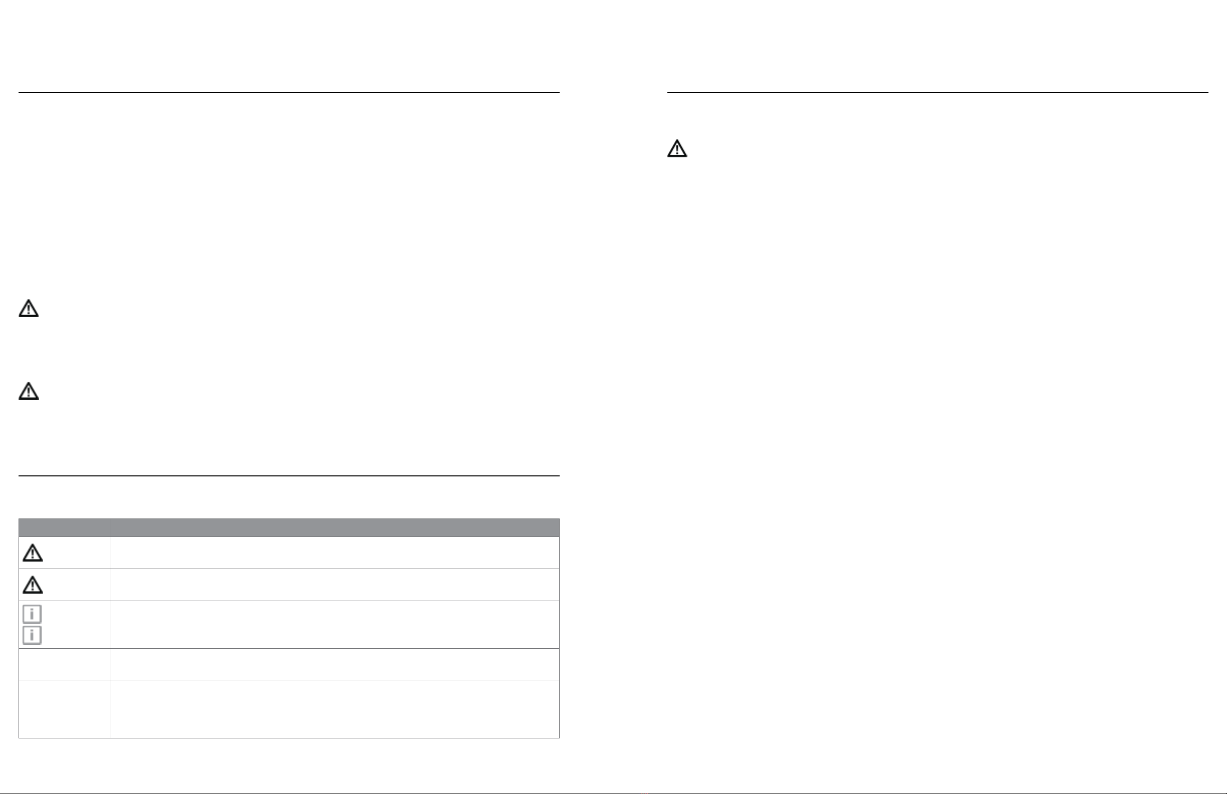
LIFE2000® VENTILATOR VERSIONS
There are two released ventilator versions of the Life2000 Ventilator. You will be able to identify the
version of the ventilator based on the REF number.
The functionality of the ventilator’s Communication Port, Battery Charge Icon, and System Alarms
dier for each version of the ventilator. Please make sure to identify the REF number of the ventilator to
ensure proper use of your system.
IDENTIFYING THE REF NUMBER
The REF number is located on the label on the back of the ventilator, see examples below.
Ventilator REF MS-01-0100,
released prior to Sept 16, 2019
Ventilator REF MS-01-0118,
released after Sept 16, 2019
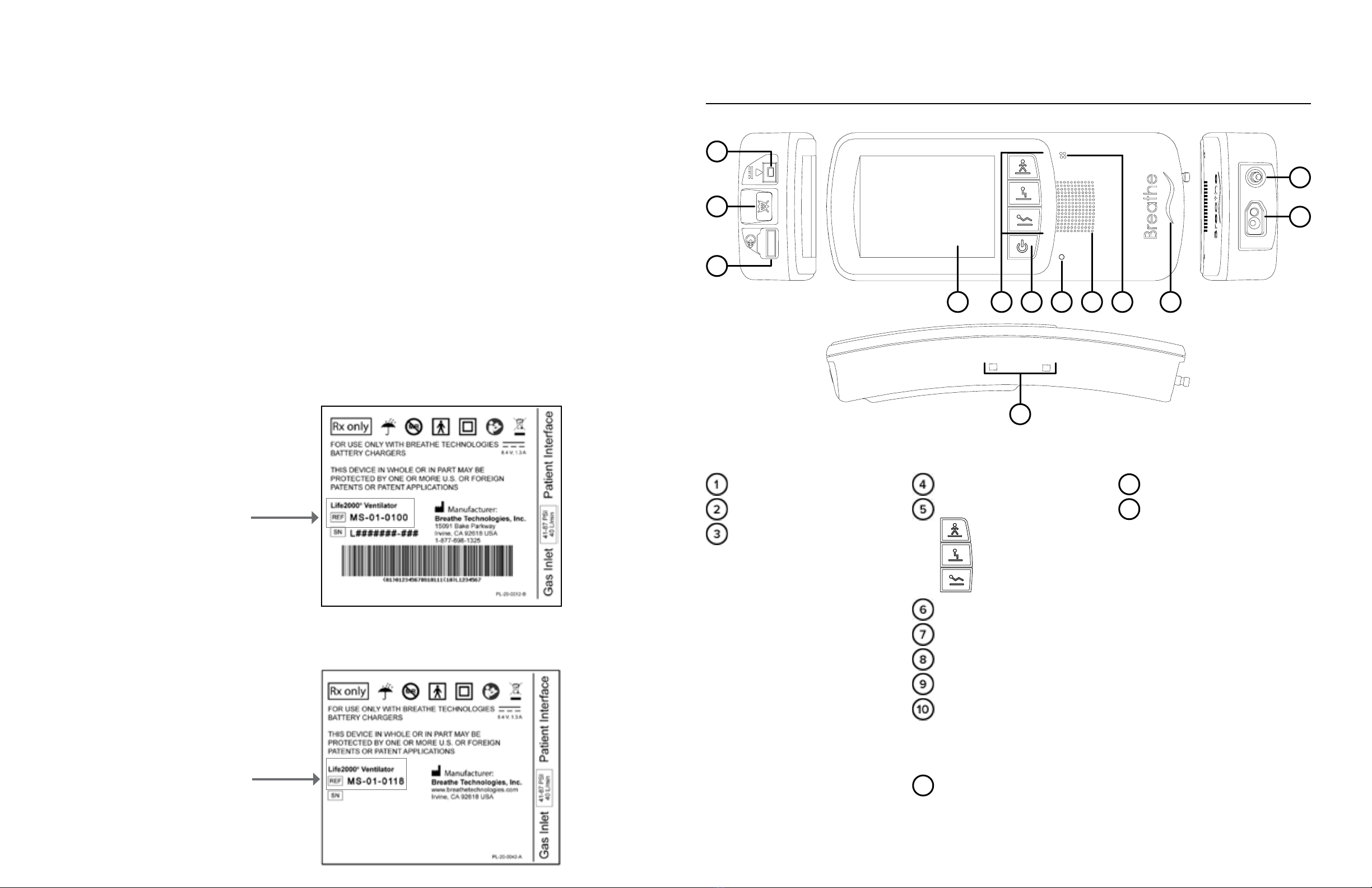
SYSTEM COMPONENTS
VENTILATOR
TOP
Battery charger connection
Silence Alarm button
Communication Port
FRONT
Touch screen
Activity buttons
High Activity button
Medium Activity button
Low Activity button
Power button for ventilator
Power indicator light
Alarm speaker
Backup alarm buzzer
Breath indicator light
SIDE
13 Belt clip sockets
BOTTOM
11 Interface connection
12 Gas inlet connection
2
3
1
4 5 6 7 8 109
11
12
13

910
LIFE2000 VENTILATION SYSTEM INTRODUCTION
1LIFE2000 VENTILATION SYSTEM INTRODUCTION
1
CONFIGURATIONS
The modular Life2000® Ventilation System (system) is composed of the Life2000® Ventilator (ventilator) and the
Life2000® Compressor (compressor). The system can be used in three dierent configurations.
STATIONARY CONFIGURATION
The ventilator is docked into the compressor for ventilation while resting. For information about how to setup the
ventilation system in this configuration, see the following chapter "Chapter 2: Stationary Configuration".
EXTENDED RANGE WEARABLE CONFIGURATION
The ventilator is connected to the compressor with a gas supply hose to enable the activities of daily living. For
information about how to setup the ventilation system in this configuration, see "Chapter 3: Extended Range
Configuration" on page 20.
STANDALONE WEARABLE CONFIGURATION
The ventilator is connected to an alternate pressure source such as a hospital wall source or an air or oxygen
cylinder. For more information about how to setup the ventilator in this configuration, see "Chapter 4: Stand-Alone
Configuration" on page 34.
18
11
12
13
15
14 16 17
COMPRESSOR
FRONT
Ventilator docking cradle
Power source indicator light
Power button for compressor
Locked icon
(ventilator charging indicator light)
Locking knob
Unlocked icon
Battery charge status button
Battery charge indicator lights
and battery charge scale
SIDE
Interface connection
Outlet fitting
BACK
11 Handle
12 Air inlet and filter
13 Cooling filter cover
Cooling vents
Condensation tray
Power supply connection
and cover
SIDE
Alarm buzzer (internal)
Silence Alarm button
0 100%
10
9
2
3
1
7
6
5 8
4
Outlet Air OnlyOutlet Air Only
11 12
STATIONARY CONFIGURATION2 STATIONARY CONFIGURATION2
POSITIONING AND CARRYING THE COMPRESSOR
Position the compressor upright on a flat, level surface. Make sure that the cooling vents, cooling filter cover, and
air inlet on the back of the compressor are not blocked, and there is sucient clearance from surrounding objects.
Protect the compressor from falling.
The compressor should not be used adjacent to or stacked with other equipment and that if adjacent or stacked
use is necessary, the compressor should be observed to verify normal operation in the configuration in which it
will be used.
When carrying the compressor, make sure to use the handle, keep the compressor in an upright position, and
protect it from falling or dropping.
NOTES:
• The compressor outputs an audible sound and must be at least 3 feet (1 m) away from the user during use.
• When operating in a 40°C (104°F) environment, the gas output by the ventilation system may reach
temperatures up to 48°C (118.4°F). To reduce patient discomfort, operate the ventilation system in a cooler
environment.
• The performance of the compressor may degrade in high temperature, high humidity, or high altitude
environments. If degradation is seen, switch to an alternate means of ventilation. Verify the performance of
the compressor for adequate therapy delivery in the environment(s) in which it will be used and adjust the
volume to compensate for altitude when necessary.
• The ventilator settings might not be achieved
when sourced by the Life2000®Compressor due
to increases in altitude near or above 2500 feet.
Consult the table to ensure that the compressor
can meet the ventilator settings. The tidal volume
delivered to the patient includes the ventilator
set volume + entrainment volume from patient
interface + supplemental oxygen volume (if used).
For additional information see page 150.
WARNING:
• Do not use the ventilation system in the presence of flammable anesthetics.
• Do not cover or block the compressor’s internal alarm buzzer with any object. Covering the buzzer may
make it dicult for a patient or caregiver to hear alarms, which may result in inadequate respiratory
therapy.
• Do not cover the ventilator, touch screen, speaker, or backup alarm buzzer with tape or any other object.
Covering the ventilator or any of its parts might cause diculty in hearing alarms and might aect ventilator
performance.
• When the ventilator is in use, keep it in a well-ventilated area to prevent it from overheating. The ventilator
may overheat and be permanently damaged if it is used in an area that is not well ventilated.
• Do not connect the ventilation system components or accessories to any other equipment that is not
described in this Instructions for Use.
CAUTION:
• Keep in a clean environment to protect the ventilation system from ingress of dust, lint, and pests.
• Do not leave the ventilation system exposed to the sun or other sources of radiant heat, it may overheat.
• Do not allow children or pets to access the ventilation system; it may become damaged.
Simulated Elevation
(in feet)
Observed Maximum
Compressor Output
(in LPM)
0 17
2500 14
4000 12
8000 8
INTRODUCTION TO STATIONARY CONFIGURATION
In Stationary Configuration, the ventilator is docked into the compressor. The compressor provides the ventilator
with a continuous pressure source and functions as a charging station.
STATIONARY CONFIGURATION SETUP CHECKLIST
Refer to the chapter contents for full instructions, warnings, and cautions.
Test the ventilator before using it on a new patient if in multi-patient environment (see section below).
Position the compressor
Connect the compressor to an AC power source using the compressor’s external power supply and AC
power cord
Dock the ventilator into the compressor
TIP: Check to make sure the ventilator is locked in the compressor.
Connect an interface to the compressor
NOTE: For information about the interface on the patient side, see "Chapter 5: Connecting an Interface" on
page 44.
Power on the compressor
Power on the ventilator
Check the compressor’s battery charge status
Check the ventilator’s battery charge
NOTE: Ventilation will not begin until an Activity button is pressed on the ventilator. For more information see
"Choosing an Activity Button (Patient Selectable) to Begin Ventilation" on page 67.
TESTING THE VENTILATION SYSTEM
In a multi-patient setting, the ventilation system must be tested before it is assigned to a new patient. For
instructions on testing the ventilation system, see "Testing Ventilator Alarms" on page 115.

13 14
STATIONARY CONFIGURATION2 STATIONARY CONFIGURATION2
DOCKING THE VENTILATOR INTO THE COMPRESSOR
NOTE: When switching between ventilation system configurations, ensure that the patient receives adequate
ventilation therapy; place the patient on an alternate means of ventilation if necessary.
Ensure that the ventilator is powered o.
NOTE: Alarms might be encountered and/or the selected Activity
Button might be inadvertently changed if the ventilator is not
powered o before docking.
To dock the ventilator into the compressor, make sure the locking
knob is in the unlock position as shown.
Position the ventilator into the compressor cradle as shown. Push the
ventilator into the compressor in the direction indicated by the arrow
until it clicks into place.
Gently push the top of the ventilator (in the area indicated) until the
front of the ventilator is flush with the front of the compressor and
clicks into place.
TIP: Avoid pushing directly on the touch screen or buttons.
1
0 100%
2
Push here
SUPPLYING POWER TO THE COMPRESSOR
An AC power cord and external power supply are included with the compressor.
Open the compressor's power supply connection cover
Insert the compressor’s power connector into the power supply
connection on the back of the compressor until it clicks into place;
the lock tab on the cord will be on the top.
Connect the AC power cord to the compressor’s external power
supply and cord.
Connect the pronged end of the compressor’s AC power cord to an AC
power source.
Verify that the green LED indicator on the external power supply lights up to indicate the AC connection.
NOTES:
• To remove the power cord from the compressor, press on the end of the lock tab on the external power
supply cord and pull to release the cord from the compressor.
• To isolate the compressor from the supply mains (AC power source), unplug the compressor's AC power
cord from the AC power source.
TIP:
The compressor’s power supply connection is equipped with a protective cover to prevent ingress of water and
debris. Use the cover to keep the power supply connection covered when not in use.
WARNING:
The interface, source gas supply hose, and power cords should be positioned to avoid restricting movement,
causing a tripping hazard, or posing a strangulation risk.
CAUTION:
• Do not place the compressor's AC power cord or external power supply on wet surfaces or use in wet
environments. Wet environments may damage the AC power cord or external power supply and may
cause electric shock.
• Use only the approved AC power cord and external power supply with the compressor. Using an
unauthorized AC power cord or external power supply may damage the compressor.
15 16
STATIONARY CONFIGURATION2 STATIONARY CONFIGURATION2
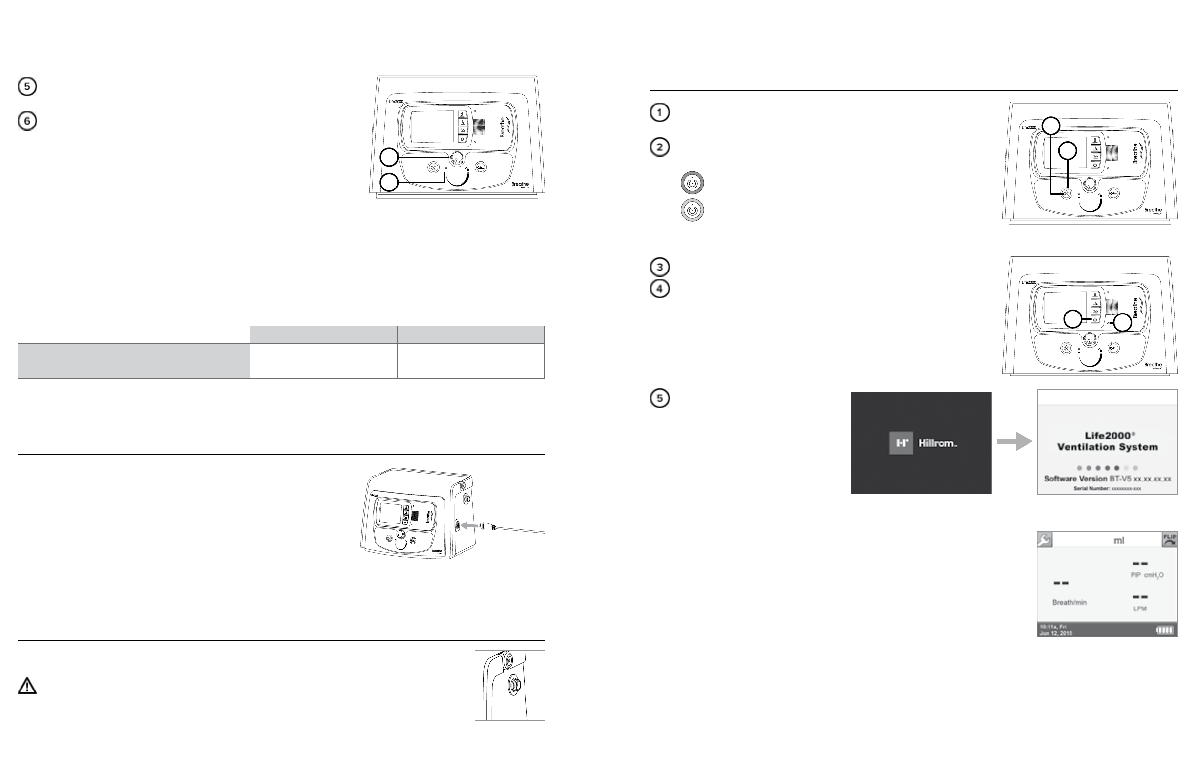
POWERING ON SEQUENCE IN STATIONARY CONFIGURATION
Power on the compressor by pressing the power button for the
compressor.
When powered on, lights surrounding the compressor power button
will illuminate:
Green indicates the compressor is connected to AC power.
Orange indicates the internal battery is being used.
NOTE: If the ventilator is properly docked, the locked icon will also
illuminate when the compressor is powered on.
Power on the ventilator by pressing the power button for the ventilator.
Ensure the green power indicator light on the ventilator is on.
When the startup screen is displayed,
listen for audible tones to test the
ventilator's alarm speaker.
During the ventilator’s start up
sequence, the ventilator will perform
a self test. During the test, all
ventilator indicator lights should
briefly flash and an audible alarm should briefly sound. This self test can take up to 15 seconds to complete.
If you do not hear tones when you turn on the ventilator, contact your service representative.
When the Home Screen is displayed, the touch screen is ready to use.
NOTE: Ventilation will not begin until an Activity Button is selected on the
ventilator. For more information see "Choosing an Activity Button (Patient
Selectable) to Begin Ventilation" on page 67.
NOTE: A high-pitched sound may be heard briefly while the compressor is
powering on. This sound will go away once the compressor reaches operating
pressure.
0 100%
1
2
0 100%
4
3
Turn the locking knob clockwise to the locked position to lock the
ventilator in the compressor.
When the compressor is on, check that the locked icon lights up
(green) to indicate the ventilator is properly docked. When the
ventilator is properly docked and locked the ventilator is being
charged by the compressor.
NOTES:
• If the compressor is o and connected to an AC power source,
press the battery charge status button on the compressor to
illuminate the green locked icon and verify that the ventilator is properly docked.
• If the knob does not lock on first attempt, turn knob slightly counterclockwise and then clockwise again.
• To ensure continuous ventilation, make sure the ventilator battery is being charged by the compressor
while the ventilator is docked. For more information see "Checking the Ventilator Battery Charge" on
page 125.
NOTE: For undocking instructions, see "Undocking the Ventilator from the Compressor" on page 23.
VENTILATOR CHARGING BY COMPRESSOR WHEN DOCKED AND LOCKED
Compressor ON Compressor OFF
AC CONNECTED to Compressor Ventilator charging Ventilator charging
AC DISCONNECTED from Compressor Ventilator charging Ventilator DOES NOT charge
NOTE: The ventilator will not charge when the compressor is powered o and not connected to AC power.
0 100%
5
6
CONNECTING AN INTERFACE TO THE COMPRESSOR
Plug the Breathe Pillows Entrainment Interface or Universal Circuit®
Connector into the interface port on the side of the compressor until it
clicks. For more information about wearing interfaces, see "Chapter 5:
Connecting an Interface" on page 44.
0 100%
THE OUTLET FITTING IN STATIONARY CONFIGURATION
Do not connect a gas source to the outlet fitting on the compressor.
CAUTION:
Using the outlet fitting while the Life2000®Ventilation System is delivering therapy in Stationary
Configuration might decrease flow to the patient.
0 100%

17 18
STATIONARY CONFIGURATION2 STATIONARY CONFIGURATION2
SILENCE ALARM BUTTON ON THE COMPRESSOR
Silencing and clearing alarms is a multi-step process that depends on alarm priority and how many alarms are
active. For more information see "Chapter 7: Alarms, Alerts, and Troubleshooting".
Press the Silence Alarm button to temporarily
silence the alarm for 60 seconds. Pressing the
Silence Alarm button silences only one alarm at a
time—in audible or vibrating alarm mode. If more
than one alarm occurs, press the Silence Alarm
button once for each alarm. If the alarm is a
medium- or high-priority alarm and is not silenced
after 60 seconds, the alarm will continue with an
additional buzzer.
Resolve the condition that triggered the alarm. For help resolving alarms, see the alarm and troubleshooting
tables in "Chapter 7: Alarms, Alerts, and Troubleshooting" for possible causes of an alarm and options to
resolve it. If an alarm silence button is pressed but the condition that triggered the alarm is not resolved, the
alarm will sound again after 60 seconds.
After resolving a High Temperature, High Circuit Pressure, or High PEEP
Pressure high-priority alarm, touch OK in the message that indicates the
alarm has been resolved.
1
500 ml
High Circuit
Peak Pressure
has been resolved.
10:11a, Fri
Jun 12, 2015
3
Values displayed on the screen are for
illustrative purposes only.
CHECKING THE COMPRESSOR’S INTERNAL BATTERY STATUS
The compressor is equipped with an internal battery for temporary AC power disruptions. This internal battery:
• charges when the compressor is attached to AC power.
• has a maximum charge of one hour.
When the compressor is powered on and the power source indicator
lights surrounding the power button are illuminated in orange the
compressor is running on its internal battery.
The battery charge indicator lights and battery charge scale surround
the battery charge status button and indicate the compressor’s
current battery charge level. Consult the charts on the following page
to determine the approximate amount of charge on the compressor’s
internal battery.
TIP:
When the compressor is o, press and hold the Battery Charge Status button to display the indicator lights in the
battery charge scale.
0 100%
1 2
19 20
EXTENDED RANGE CONFIGURATION3STATIONARY CONFIGURATION2
INTRODUCTION TO EXTENDED RANGE CONFIGURATION
The Life2000® Ventilation System can be used in dierent configurations of operation as the patient’s needs
change. In Extended Range Configuration, the ventilator is connected to the compressor with an oxygen hose to
enable the activities of daily living.
NOTE: If not directly connected to AC power, make sure the ventilator battery has sucient charge for your
length of use.
EXTENDED RANGE CONFIGURATION SETUP CHECKLIST
Refer to the chapter contents for full instructions, warnings, and cautions.
Test the ventilator before using it on a new patient if in multi-patient environment (see section below).
Position the compressor.
Connect the compressor to an AC power source using the compressor’s external power supply and AC
power cord.
Undock the ventilator from the compressor.
Connect the compressor and the ventilator with an oxygen hose.
Connect an interface to the ventilator.
NOTE: For information about the interface on the patient side, see "Chapter 5: Connecting an Interface" on
page 44.
Power on the compressor.
Power on the ventilator.
Check the compressor’s battery charge status.
Check the ventilator’s battery charge and charge the ventilator, if necessary.
Secure the ventilator using the belt clip or pole mount.
NOTE: Ventilation will not begin until an Activity button is pressed on the ventilator. For more information see
"Choosing an Activity Button (Patient Selectable) to Begin Ventilation" on page 67.
TESTING THE VENTILATION SYSTEM
In a multi-patient setting, the ventilation system must be tested before it is assigned to a new patient. For
instructions on testing the ventilation system, see "Testing Ventilator Alarms" on page 115.
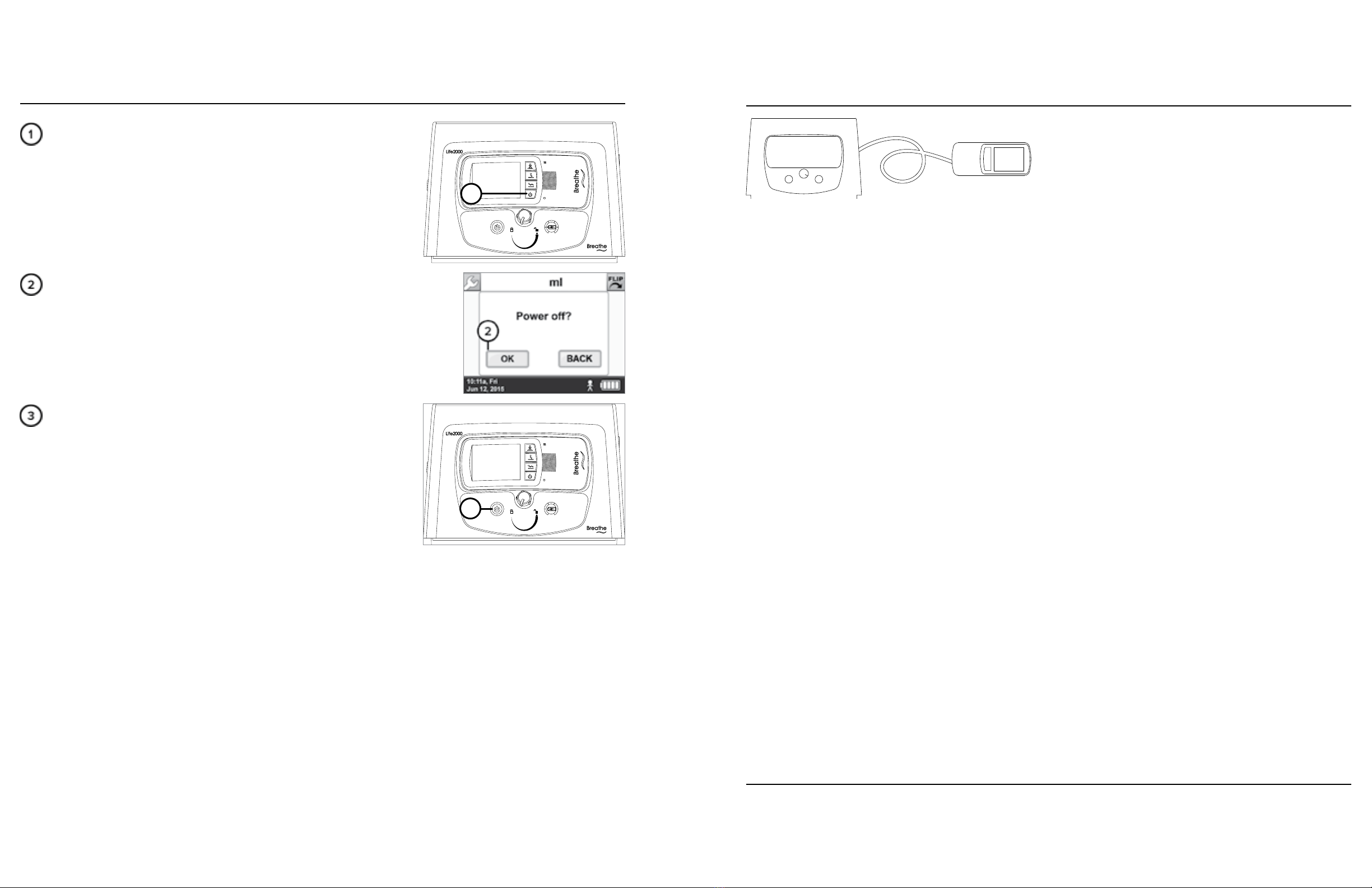
POWERING OFF SEQUENCE IN STATIONARY CONFIGURATION
To power o the ventilator, press the ventilator's power button for
three seconds until a confirmation screen appears.
To continue to power o the ventilator, choose OK.
NOTE: If a selection is not made within 20 seconds or if the BACK button is
selected, the previous screen will be displayed and the ventilation status will
not be aected.
To power o the compressor, press the compressor's power button.
NOTE: To isolate the compressor from the supply mains (AC power
source), unplug the compressor's AC power cord from the AC power
source.
0 100%
1
0 100%
3

21 22
EXTENDED RANGE CONFIGURATION3 EXTENDED RANGE CONFIGURATION3
SUPPLYING POWER TO THE COMPRESSOR
An AC power cord and external power supply are included with the compressor.
Open the compressor's power supply connection cover.
Insert the compressor’s power connector into the power supply
connection on the back of the compressor until it clicks into place;
the lock tab on the cord will be on the top.
Connect the AC power cord to the compressor’s external power supply
and cord.
Connect the pronged end of the compressor’s AC power cord to an AC
power source.
Verify that the green LED indicator on the external power supply lights up to indicate the AC connection.
NOTES:
• To remove the power cord from the compressor, press on the end of the lock tab on the external power
supply cord and pull to release the cord from the compressor.
• To isolate the compressor from the supply mains (AC power source), unplug the compressor's AC power
cord from the AC power source.
TIP:
The compressor’s power supply connection is equipped with a protective cover to prevent ingress of water and
debris. Use the cover to keep the power supply connection covered when not in use.
WARNING:
The interface, source gas supply hose, and power cords should be positioned to avoid restricting movement,
causing a tripping hazard, or posing a strangulation risk.
CAUTION:
• Do not place the compressor's AC power cord or external power supply on wet surfaces or use in wet
environments. Wet environments may damage the AC power cord or external power supply and may
cause electric shock.
• Use only the approved AC power cord and external power supply with the compressor. Using an
unauthorized AC power cord or external power supply may damage the compressor.
POSITIONING AND CARRYING THE COMPRESSOR
Position the compressor upright on a flat, level surface. Make sure that the cooling vents, cooling filter cover, and
air inlet on the back of the compressor are not blocked, and there is sucient clearance from surrounding objects.
Protect the compressor from falling.
The compressor should not be used adjacent to or stacked with other equipment and that if adjacent or stacked
use is necessary, the compressor should be observed to verify normal operation in the configuration in which it
will be used.
When carrying the compressor, make sure to use the handle, keep the compressor in an upright position, and
protect it from falling or dropping.
NOTES:
• The compressor outputs an audible sound and must be at least 3 feet (1 m) away from the user during use.
• When operating in a 40°C (104°F) environment, the gas output by the ventilation system may reach
temperatures up to 48°C (118.4°F). To reduce patient discomfort, operate the ventilation system in a cooler
environment.
• The performance of the compressor may degrade in high temperature, high humidity, or high altitude
environments. If degradation is seen, switch to an alternate means of ventilation. Verify the performance of
the compressor for adequate therapy delivery in the environment(s) in which it will be used and adjust the
volume to compensate for altitude when necessary.
• The ventilator settings might not be achieved
when sourced by the Life2000®Compressor due
to increases in altitude near or above 2500 feet.
Consult the table to ensure that the compressor
can meet the ventilator settings. The tidal volume
delivered to the patient includes the ventilator
set volume + entrainment volume from patient
interface + supplemental oxygen volume (if used).
For additional information see page 150.
WARNING:
• Do not use the ventilation system in the presence of flammable anesthetics.
• Do not cover or block the compressor’s internal alarm buzzer with any object. Covering the buzzer may
make it dicult for a patient or caregiver to hear alarms, which may result in inadequate respiratory
therapy.
• Do not cover the ventilator, touch screen, speaker, or backup alarm buzzer with tape or any other object.
Covering the ventilator or any of its parts might cause diculty in hearing alarms and might aect ventilator
performance.
• When the ventilator is in use, keep it in a well-ventilated area to prevent it from overheating. The ventilator
may overheat and be permanently damaged if it is used in an area that is not well ventilated.
• Do not connect the ventilation system components or accessories to any other equipment that is not
described in this Instructions for Use.
CAUTION:
• Keep in a clean environment to protect the ventilation system from ingress of dust, lint, and pests.
• Do not leave the ventilation system exposed to the sun or other sources of radiant heat, it may overheat.
• Do not allow children or pets to access the ventilation system; it may become damaged.
Simulated Elevation
(in feet)
Observed Maximum
Compressor Output
(in LPM)
0 17
2500 14
4000 12
8000 8
23 24
EXTENDED RANGE CONFIGURATION3 EXTENDED RANGE CONFIGURATION3
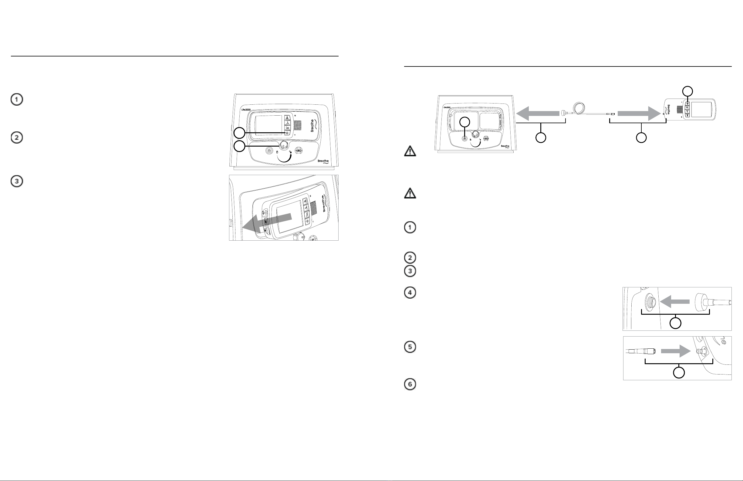
UNDOCKING THE VENTILATOR FROM THE COMPRESSOR
NOTE: When switching between ventilation system configurations, ensure that the patient receives adequate
ventilation therapy; place the patient on an alternate means of ventilation if necessary.
Power o the ventilator.
NOTE: Alarms might be encountered and/or the selected Activity
Button might be inadvertently changed if the ventilator is not
powered o before undocking.
Turn the locking knob counterclockwise to the unlocked position until
the compressor ejects the ventilator.
NOTE: Some tension will be encountered while turning the knob
during ejection.
Pull the ventilator (in the direction shown by the arrow) to separate it
from the compressor cradle.
NOTE: For docking instructions, see "Docking the Ventilator into the
Compressor" on page 14.
0 100%
1
2
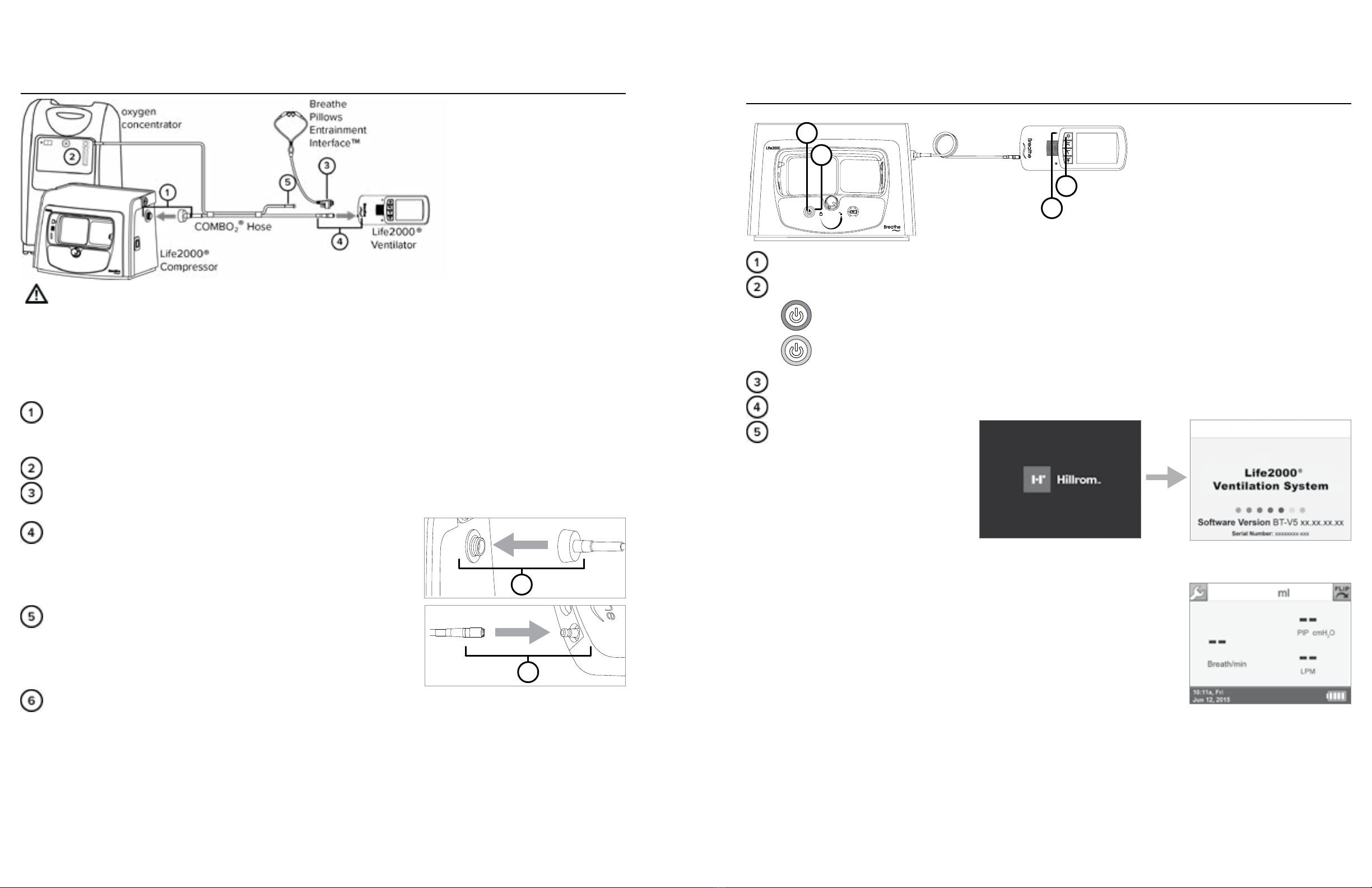
CONNECTING THE VENTILATOR AND COMPRESSOR IN
EXTENDED RANGE CONFIGURATION
In this configuration, the ventilator and compressor are connected by an oxygen hose; this allows use of the
ventilator without having to be docked into the compressor. A six-foot oxygen hose is included with the ventilation
system.
WARNING:
The interface, source gas supply hose, and power cords should be positioned to avoid restricting movement,
causing a tripping hazard, or posing a strangulation risk.
CAUTION: Use only an approved oxygen hose with the ventilation system.
NOTE: A 20-foot source gas supply hose (available to order) is recommended when using a ventilator output
volume greater than 350 ml.
Ensure the ventilator is powered o.
NOTE: Alarms might be encountered and/or the selected Activity Button might be inadvertently changed if
the ventilator is not powered o.
The compressor may be powered o or powered on.
Undock the ventilator from the compressor; for more information, see "Undocking the Ventilator from the
Compressor" on page 23.
Attach the oxygen hose to the outlet fitting on the compressor.
NOTE: The outlet fitting is to be used only for connecting the
compressor to the Life2000®Ventilator with an approved source gas
supply hose or during the purging of an interface. For more
information about the purging process see "Purging the Universal
Circuit® Connector" on page 108.
Connect the other end of the oxygen hose to the ventilator by
pushing the small quick connect end onto the gas inlet connection on
the ventilator; when connected, the quick connect end will click into
place.
For more information about powering on, see "Powering On
Sequence in Extended Range Configuration" on page 28.
NOTES:
• Ventilation will not begin until an Activity Button is selected on the ventilator. For more information see
"Choosing an Activity Button (Patient Selectable) to Begin Ventilation" on page 67.
• During use in Extended Range Configuration, the oxygen hose should remain connected to the ventilator
at all times, except when required to be disconnected for maintenance, testing, or replacement. If it is
disconnected while the ventilator is on and delivering therapy, a Low Gas Pressure alarm will occur. For
more information see "Low Gas Pressure" on page 90.
1
4
0 100%
2
5
Oxygen hose Ventilator
Compressor
4
5
25 26
EXTENDED RANGE CONFIGURATION3 EXTENDED RANGE CONFIGURATION3
CONNECTING AN INTERFACE TO THE VENTILATOR IN EXTENDED RANGE
CONFIGURATION
Plug the Breathe Pillows Entrainment Interface or Universal Circuit®
Connector into the interface port on the bottom of the ventilator until it
clicks. For more information about wearing interfaces, see "Chapter 5:
Connecting an Interface" on page 44.
NOTE: Ensure that the Breathe Pillows Entrainment Interface or Universal
Circuit®Connector is connected to the ventilator in Extended Range
Configuration and Stand-Alone Configuration.
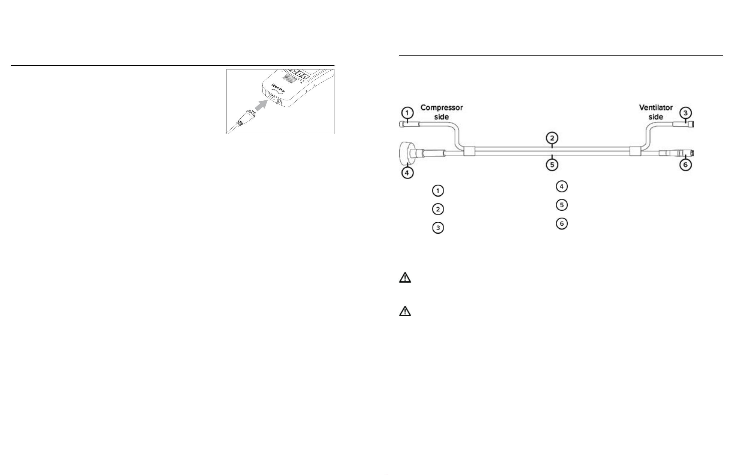
THE COMBO2® HOSE
The CombO2® hose may be used to connect the Life2000® Ventilation System in Extended Range Configuration
and provide supplemental low-flow oxygen from an oxygen concentrator or other low-flow oxygen source.
WARNING:
The interface, source gas supply hose, and power cords should be positioned to avoid restricting movement,
causing a tripping hazard, or posing a strangulation risk.
CAUTION
Use only an approved source gas supply hose with the ventilation system. If an unauthorized source gas supply
hose is used with the ventilation system, the system may be damaged.
NOTES:
• Visually inspect the CombO2® hose before using it.
• During use in Extended Range Configuration, the source gas supply hose should remain connected to the
ventilator at all times, except when required to be disconnected for maintenance, testing, or replacement. If
it is disconnected while the ventilator is on and delivering therapy, a Low Gas Pressure alarm will occur.
Oxygen tubing connector
Oxygen tubing
Oxygen tubing Connector
Outlet fitting connector
Source Gas Supply hose
Quick connect end
27 28
EXTENDED RANGE CONFIGURATION3 EXTENDED RANGE CONFIGURATION3
CONNECTING TO A LOWFLOW OXYGEN SOURCE USING THE COMBO2®HOSE
WARNING:
The interface, source gas supply hose, and power cords should be positioned to avoid restricting movement,
causing a tripping hazard, or posing a strangulation risk.
NOTE: A 20-foot source gas supply hose (available to order) is recommended when using a ventilator output
volume greater than 350 ml.
Ensure the ventilator is powered o.
NOTE: Alarms might be encountered and/or the selected Activity Button might be inadvertently changed if
the ventilator is not powered o.
The compressor may be powered o or powered on.
Undock the ventilator from the compressor; for more information, see "Undocking the Ventilator from the
Compressor" on page 23.
Attach the outlet fitting connector on the CombO2® hose to the
outlet fitting on the compressor.
NOTE: The outlet fitting is to be used only for connecting the
compressor to the Life2000® Ventilator with an approved source gas
supply hose or during the purging of an interface.
Connect the quick connect end on the CombO2® hose to the
ventilator by pushing the small quick connect end onto the gas inlet
connection on the ventilator; when connected, the quick connect
end will click into place.
For more information about powering on, see "Powering On Sequence in Extended Range Configuration" on
page 28.
NOTES:
• Ventilation will not begin until an Activity Button is selected on the ventilator. For more information see
"Choosing an Activity Button (Patient Selectable) to Begin Ventilation" on page 67.
4
5
POWERING ON SEQUENCE IN EXTENDED RANGE CONFIGURATION
0 100%
1
2
3
4
Power on the compressor by pressing the power button for the compressor.
When powered on, lights surrounding the compressor power button will illuminate:
Green indicates the compressor is connected to AC power.
Orange indicates the internal battery is being used.
Power on the ventilator by pressing the power button for the ventilator.
Ensure the green power indicator light on the ventilator is on.
When the startup screen is displayed,
listen for audible tones to test the
ventilator's alarm speaker.
During the ventilator’s start up
sequence, the ventilator will perform
a self test. During the test, all
ventilator indicator lights should
briefly flash and an audible alarm should briefly sound. This self test can take up to 15 seconds to complete.
If you do not hear tones when you turn on the ventilator, contact your service representative.
When the Home Screen is displayed, the touch screen is ready to use.
NOTE: Ventilation will not begin until an Activity Button is selected on the
ventilator. For more information see "Choosing an Activity Button (Patient
Selectable) to Begin Ventilation" on page 67.
NOTE: A high-pitched sound may be heard briefly while the compressor is
powering on. This sound will go away once the compressor reaches operating
pressure.
29 30
EXTENDED RANGE CONFIGURATION3 EXTENDED RANGE CONFIGURATION3
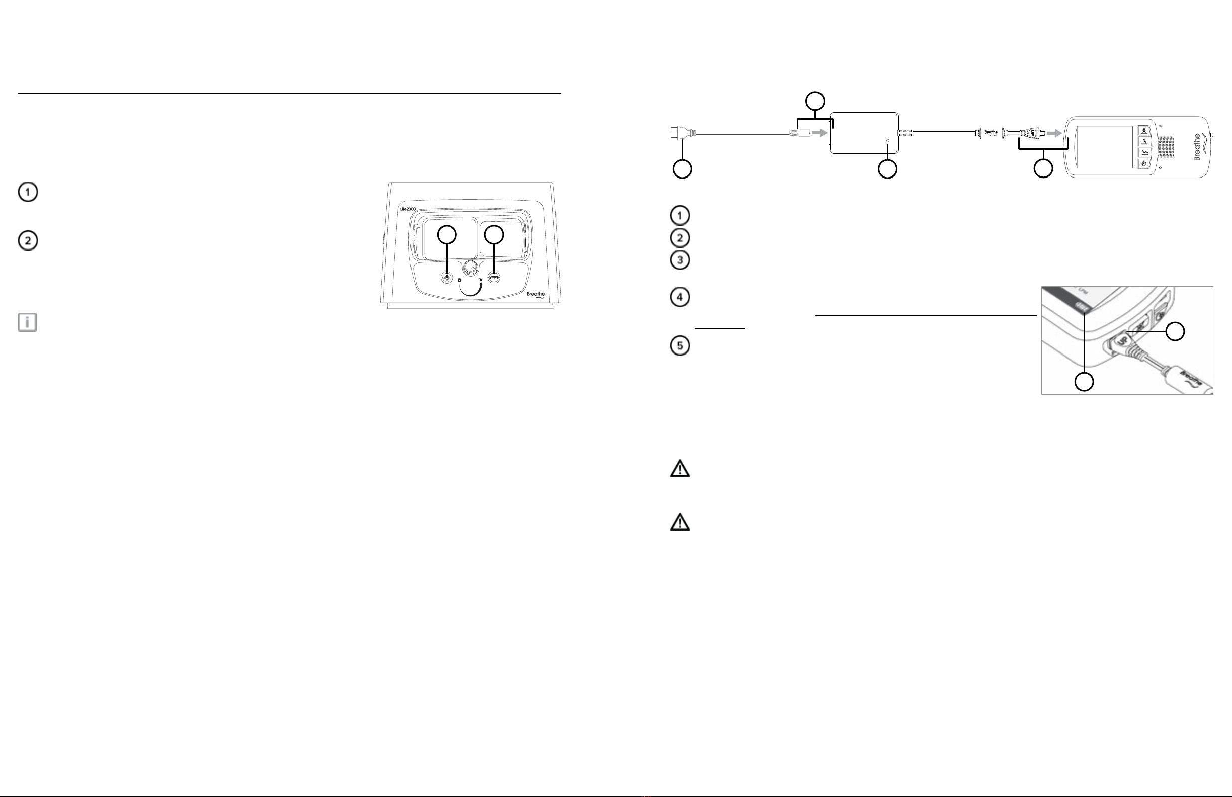
ASSEMBLING THE VENTILATOR BATTERY CHARGER AND CHARGING THE VENTILATOR
Ventilator
Battery chargerAC power cord
4
3
2
1
Plug the ventilator AC power cord into the ventilator battery charger.
Connect the ventilator AC plug into an AC power source.
The ventilator battery charger indicator light will turn green or red when connected to AC power.
NOTE: The ventilator can be used while the battery is charging.
Connect the ventilator battery charger cord to the ventilator battery
charger connection port. The word UP on the battery charger cord will
be on top.
If powered on, check the Ventilator Battery Charge icon on the touch
screen to see the ventilator’s current battery charge status.
NOTES:
• When charging the battery, there may be a delay up to 20
seconds before the Ventilator Battery Charge icon appears on
the touch screen.
• The ventilator performance is the same regardless of power source (internal battery or AC).
• If the battery charger cord is incorrectly inserted, the charger connection may become loose over time.
WARNING:
The interface, source gas supply hose, and power cords should be positioned to avoid restricting movement,
causing a tripping hazard, or posing a strangulation risk.
CAUTION:
• Do not place the battery charger on wet surfaces or use in wet environments. Wet environments may
damage the battery charger and may cause electric shock.
• Use only the approved battery charger and cord set with the ventilator. If an unauthorized battery charger
or cord set is used with the ventilator, the ventilator may be damaged.
4
5
CHECKING THE COMPRESSOR’S INTERNAL BATTERY STATUS
The compressor is equipped with an internal battery for temporary AC power disruptions. This internal battery:
• charges when the compressor is attached to AC power.
• has a maximum charge of one hour.
When the compressor is powered on and the power source
indicator lights surrounding the power button are illuminated in
orange the compressor is running on its internal battery.
The battery charge indicator lights and battery charge scale surround
the battery charge status button and indicate the compressor’s
current battery charge level. Consult the charts on the following page
to determine the approximate amount of charge on the compressor’s
internal battery.
TIP:
When the compressor is o, press and hold the Battery Charge Status button to display the indicator lights in the
battery charge scale.
0 100%
1 2

31 32
EXTENDED RANGE CONFIGURATION3 EXTENDED RANGE CONFIGURATION3
VENTILATOR SILENCE ALARM BUTTON
Silencing and clearing alarms is a multi-step process that depends on alarm priority and how many alarms are
active. For more information see "Chapter 7: Alarms, Alerts, and Troubleshooting".
Silence Alarm button on ventilator.
Press the Silence Alarm button to temporarily silence the alarm for 60
seconds. Pressing the Silence Alarm button silences only one alarm
at a time—in audible or vibrating alarm mode. If more than one alarm
occurs, press the Silence Alarm button once for each alarm. If the
alarm is a medium- or high-priority alarm and is not silenced after 60
seconds, the alarm will continue with an additional buzzer.
Resolve the condition that triggered the alarm. For help resolving
alarms, see the alarm and troubleshooting tables in "Chapter 7: Alarms, Alerts, and Troubleshooting" for
possible causes of an alarm and options to resolve it. If a Silence Alarm button is pressed but the condition
that triggered the alarm is not resolved, the alarm will sound again after 60 seconds.
After resolving a High Temperature, High Circuit Pressure, or High PEEP
Pressure high-priority alarm, touch OK in the message that indicates the
alarm has been resolved.
1
500 ml
High Circuit
Peak Pressure
has been resolved.
10:11a, Fri
Jun 12, 2015
3
Values displayed on the screen are for
illustrative purposes only.
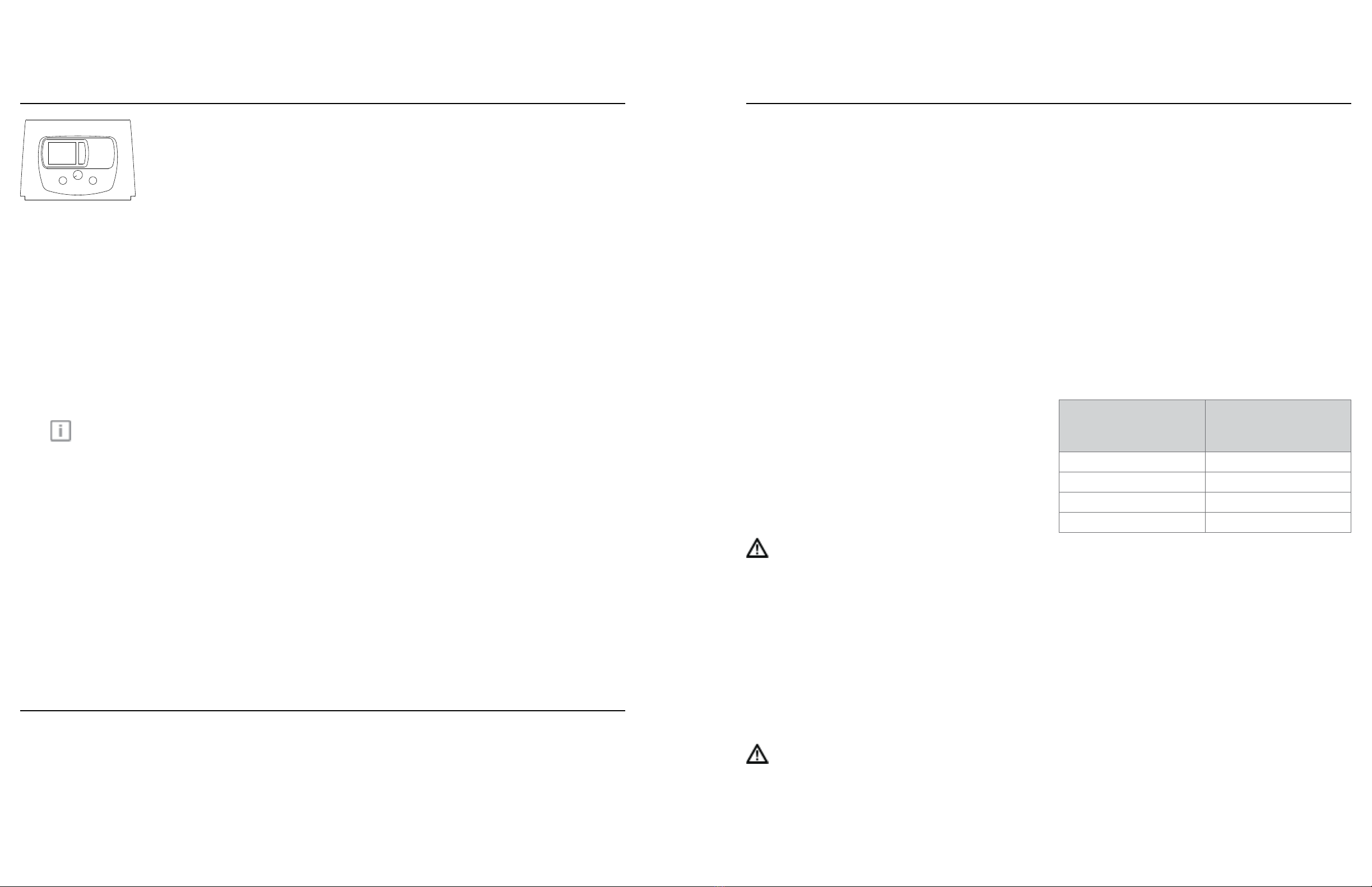
SECURING THE VENTILATOR
BELT CLIP
You can attach the ventilator to a belt or waistband using the included belt clip. The ventilator can be worn on
either the right or left side.
CAUTION:
• Make sure the belt clip is securely fastened to the belt and the ventilator. If the belt clip is not securely
fastened to the belt and the ventilator, the ventilator may fall and be damaged.
• Always secure the ventilator to prevent it from falling or becoming damaged.
• Use only the approved belt clip with the ventilator.
Position the clip over the belt, and push down until it is secure.
Line up the belt clip with the belt clip sockets on the ventilator. Push
in the ventilator towards the belt clip until the ventilator audibly clicks
into place.
POLE MOUNT
The ventilator may also be secured with the use of an optional pole mount. For more information, see "Pole
Mount" on page 41.
Table of contents


