Hills Heritage Hoist 6-Line User manual
Heritage Hoist 6-Line
Heritage Hoist 7-Line
Heritage TM
Rotary Hoist
Product Manual
2Introduction
Congratulations
Congratulations on the purchase of your Hills
Heritage Hoist, which will bring you many years
It is important that you read thisProduct Manual
thoroughly before installation and use.In this
wayyou will benefit from all the design features
and enjoy safe use of the product.
Thank you for choosing Hills.
Warning
• Do not allow children or petsto swing on
theHoist or items of laundry.
• Do not use for any purpose other than
to hang and drywashing.
• Do not use your Hoist if parts are worn
or damaged.
• Patents and registered designs applyto
this product.
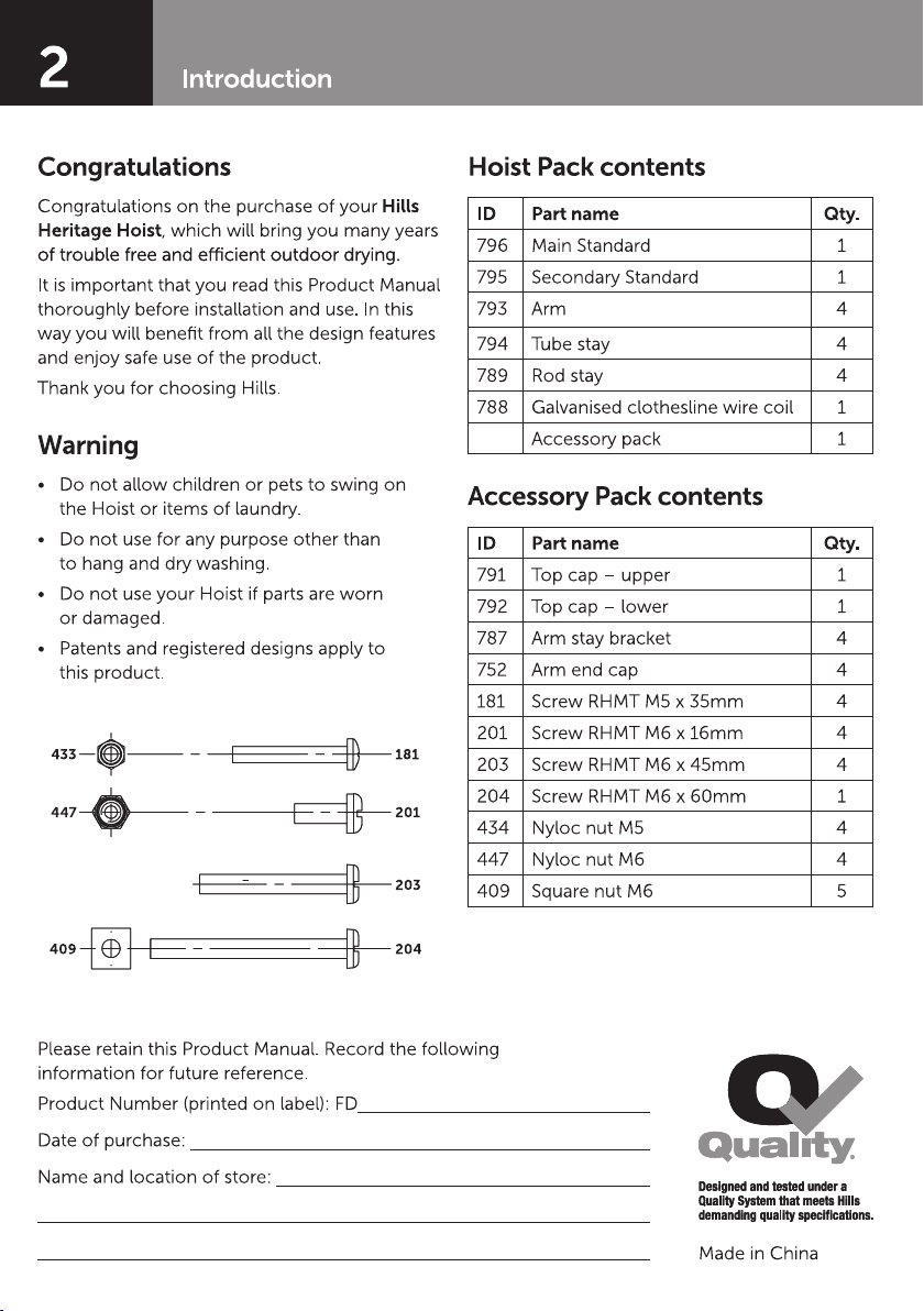
HoistPack contents
ID Part name Qty.
796 Main Standard 1
795 Secondary Standard 1
793 Arm 4
794 Tube stay 4
789Rod stay 4
788 Galvanised clothesline wire coil 1
Accessorypack 1
Accessory Pack contents
ID Part name Qty.
791 Top cap – upper 1
792 Top cap –lower 1
787 Arm staybracket 4
752 Arm end cap 4
181 Screw RHMTM5x 35mm 4
201 Screw RHMTM6 x16mm 4
203 Screw RHMTM6 x45mm 4
204 Screw RHMTM6 x60mm 1
434 Nyloc nut M5 4
447 Nyloc nut M6 4
409 Square nut M6 5
Please retain this Product Manual. Record the following
information for future reference.
Product Number (printed on label):FD
Date of purchase:
Nameand location of store:
Made in China
433 181
447 201
409 204
203
3
Installation
Select a Suitable Location
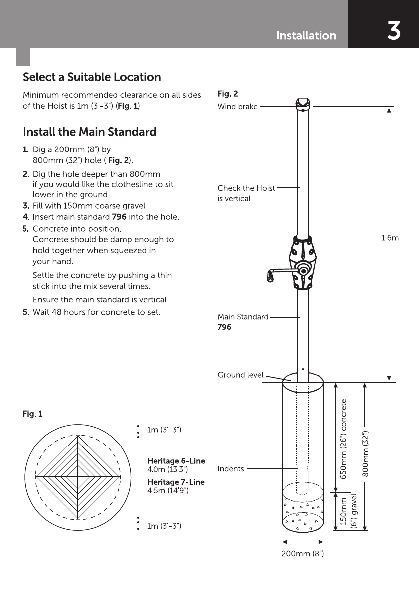
Minimum recommended clearance on all sides
of the Hoist is1m (3'-3") (Fig. 1).
Install the Main Standard
1. Dig a 200mm (8") by
800mm (32") hole (Fig. 2).
2. Dig the hole deeper than 800mm
if you would like the clothesline to sit
lower in the ground.
4. Insert main standard 796into the hole.
5.
Concrete into position.
Concrete should be damp enough to
hold together when squeezed in
your hand.
Settlethe concrete by pushing a thin
stick into the mixseveraltimes.
Ensure the main standard is vertical.
5. Wait 48 hours for concrete to set.
Fig. 2
Wind brake
Check the Hoist
is vertical
Main Standard
796
Indents
200mm (8")
1.6m
800mm (32")
650mm (26") concrete150mm
(6") gravel
Ground level
1m (3'-3")
Heritage 6-Line
4.0m (13'3")
Heritage 7-Line
4.5m (14'9")
1m (3'-3")
Fig. 1
3. Fill with 150mm coarse gravel

4Assembly
Arm andStay Assembly
1. Fit top cap lower assembly 792to secondary
standard assembly 795and fasten securely
with screw 204and nut 409 (Fig. 5).
2. Locate arm staybracket 787 onto the arm
793and align themount holes.
Ensure the bracket is assembled as per Fig 6
(with staples up).
3. Squeeze the arm staybracket 787 together
and fasten securely with screws 181and nuts
434(Fig. 6).
4. Fit tubestays 794to arm staybrackets 787
and fasten securely with screws 201and
nuts 447(Fig. 6).
5. Place the arms intothe cross and assemble
the tube stay intothe top cap assembly 791
and 792with the screw 203.
Note:Do not fit the nut yet.
6. Repeat step 5 for the other three arms.
For Model4 fit nuts 409 to screws 203now.
For Model5 refer tostep 7.
7. For Model 5, hook the inner rod stays 789
into the innermost staples on thearms.
Position other end underneath the top cap
lower assembly 792and onto screw 203.
Fit nuts 409 and tighten.
8. Fit end caps 752to the end of each arm.
Secondary Standard Assembly
1. Remove the wind brake and plastic ring
ring from thetop of theMain Standard
assemblyby loosening the securing screw.
2. Insert secondary standard 795into top of
main standard.
3. Rotate secondary standard 795until worm
hook slidesthrough theslot in stabiliser plug
(Fig 3).
4. Drop the wind brake and plastic ring on the
top of the secondary standard. Slide them
back down to their original position and
screw into place.
Fig. 3
Note: Main Standard tube
shown in dotted line for
illustration purposes.
IMPORTANT:

5
5
Cross
796
752
794
793
203
791
792
204409
Cross
409
789
795
794
794
409
Assembly
794
787 201
Staple
447 793
434
181
787
795
Assembly
Fig. 4
Fig. 5 Fig. 6
6Assembly
Wire Assembly
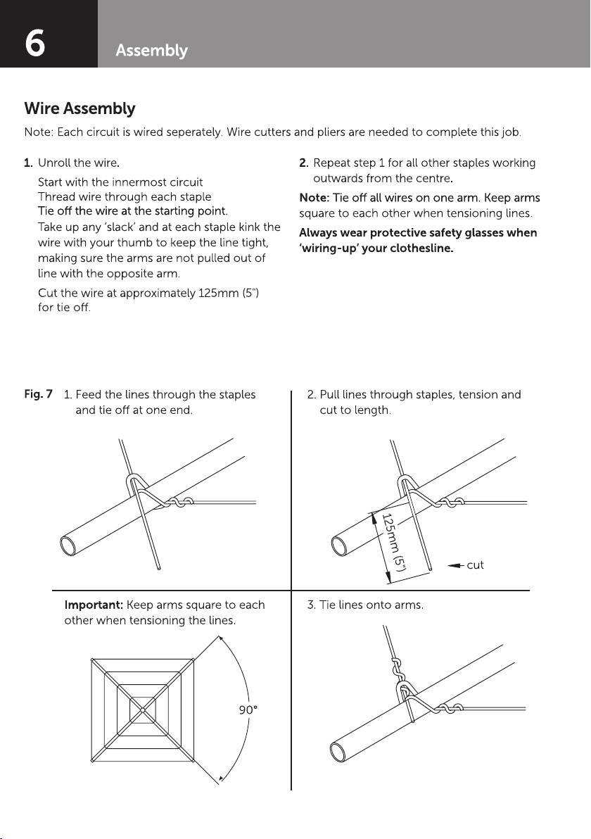
1. Unroll thewire.
Start with the innermost circuit
Thread wire through each staple
Take up any ‘slack’ and at each staple kink the
wire with your thumb to keep the line tight,
making sure the armsare not pulled out of
line with the opposite arm.
Cut the wire at approximately 125mm (5")
for tie o.
2. Repeat step 1 for all other staples working
outwards from the centre.
Note:
square to each other when tensioning lines.
Always wear protective safety glasses when
‘wiring-up’ your clothesline.
Fig. 71. Feed the lines through the staples
Important:Keep arms square toeach
other when tensioning the lines.
2. Pull linesthrough staples, tension and
cut to length.
3. Tie linesontoarms.
125mm (5")
cut
90°
Note: Each circuit is wired seperately. Wire cutters and pliers are needed to complete this job.
7
Assembly
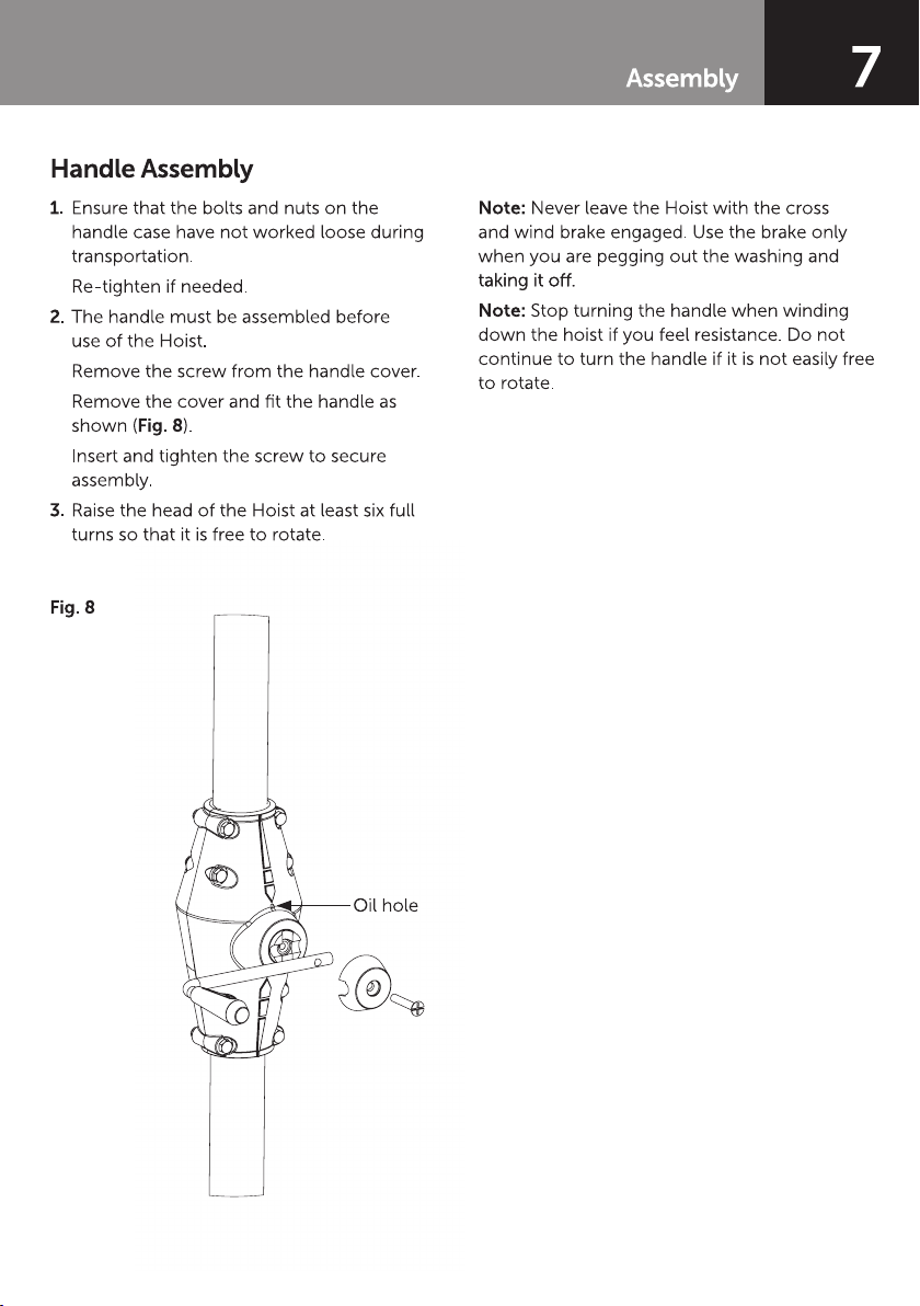
Handle Assembly
1. Ensure that thebolts and nuts on the
handlecase have not worked loose during
transportation.
Re-tighten if needed.
2. Thehandle must beassembled before
use of the Hoist.
Remove the screw from the handle cover.
Remove thecover and fit the handle as
shown (Fig. 8).
Insert and tighten the screw to secure
assembly.
3. Raise the head of the Hoist at least six full
turns so that it is free to rotate.
Note:Never leave the Hoist with the cross
and wind brake engaged.Use the brake only
when youare pegging out the washing and
Note:Stop turning the handle when winding
down the hoist if you feel resistance. Do not
continue toturn the handle if it isnot easily free
to rotate.
Fig. 8
Oil hole

8
Hills Handy Hints
• Commencehanging the washing on the
inside line starting with the smallest garments
and work your way outwards.
• The wind brake assists in the pegging and
unpegging of clothes on a windydayby
restricting the free rotation of the Hoist.It can
be engaged by winding the Hoist fullydown.
• To save excess walking, rotate the Hoist
by pulling onearm and thewind brake will
position in the next bay for loading.
• After hanging out your washing it is
recommended that the handle be wound up
at least sixfull turns to disengage the wind
brake.
• For faster drying elevate the Hoist fully to
collect any breeze. The rotating action of
the Hoist gives natural spin drying of your
washing.
Care and Maintenance
It is a good idea to occasionally inspect all
componentsand check for wear and tear or
damage. If there is anydamage, parts should be
replaced with originalHills spares or the Hoist
repaired before using again.
The Hoist should be periodically wiped clean
with a damp cloth and mild detergent.
1. To lubricate the worm gear and handle
assemblyperform the following:
a. Apply a few drops of oil through the oil
hole in the gear case abovethe handle
shaft (Fig. 8). Use any light gradeoil or
Lanonlin based lubricant.
Note:Should theHoist squeak when rotating,
wind theHoist up and apply (rub) a small
amount of bar soap on theelevated section of
the secondary standard 795(Fig.4).
Handy Hints

9
10-Year Warranty*
*In addition to other rights and remedies that
may be available under any applicable law,
Cyclone ToolsPty Ltd warrants to the purchaser
of the product (customer) that this Clothesline
will be free from defects in workmanship and
materials for 10 yearsand the Galvanised Wire
for 1 year from the date of purchase of the
product. If a defect in material or workmanship
becomes evident during that period, Cyclone
Tools Pty Ltd will, at its option, either:
• replace the product; or
• refund tothe customer the purchase price
paid by the customer for the product.
In the event of such a defect, the product
should be returned to the place of purchase
of the product bythecustomer, together
with proof of purchase, for replacement or
refund. Any handling and transportation (and
other expenses incurred in claiming under this
warranty) are not covered by this warrantyand
will be borne by the customer, not Cyclone
Tools Pty Ltd.
The obligation of Cyclone ToolsPty Ltd under
this warranty is limited to the circumstances set
out above and is subject to:
• theproduct not having been altered,
tampered with or otherwisedealt with byany
person in a manner other than as intended in
respect of the relevant product;and
• theproduct not having been used or applied
in a manner that is contrary to customary
usage or application of the relevant product
or contraryto anystated instructionsor
specification of Cyclone ToolsPty Ltd (or its
related bodiescorporate).
For products purchased in Australia:
Our goods come with guaranteesthat cannot
be excluded under the Australian Consumer
Law. You are entitled toa replacement or
refund for a major failure and compensation
for anyother reasonably foreseeableloss or
damage. You are also entitled to have the goods
repaired or replaced if thegoods fail tobe of
acceptable quality and the failure does not
amount to a major failure.
For products purchased in New Zealand:
Our goods come with guaranteesthat cannot
be excluded under the Consumer Guarantees
Act. Cyclone Tools Pty Ltd will comply with
our obligations to you under the Consumer
Guarantees Act.
Cyclone Tools Pty Ltd
ABN 89169 427 061
Level 1, 660Doncaster Road,
Doncaster Vic3108
Phone:1300 300564
Email: hhl.enquiries@amesau.com
Warranty
10 Contacts
Hills Contacts
We are committed to providing you with
complete customer satisfaction.If youhave any
questions or commentsabout our productsor
servicesplease contact your nearest Customer
Service Centre during their local business hours:
Australia
1300 300 564
New Zealand
0800 021 027
Email
hhl.enquiries@amesau.com
Hills Websites
hillshome.com.au
Hills Home Living
hillshome.com.au/need-help/
Hills Consumer Advice

11
Notes

12
Cyclone Tools Pty Ltd.
A.B.N. 89 169 427 061
Issue May2017
HD10842c
This manual suits for next models
1
Table of contents
Popular Irrigation System manuals by other brands


Viking
Viking VK506 Technical bulletin

Autopot
Autopot 36Pot system Set-up guidelines

Tyco Fire Product
Tyco Fire Product CENTRAL CC1 instruction manual

Tyco Fire Product
Tyco Fire Product CENTRAL BV-QR instruction manual

Philips
Philips sonicare AirFloss Ultra user manual

Tyco Fire Product
Tyco Fire Product SIN S3230 manual


