Hilti DD 130 User manual

DD130
Bedienungsanleitung 1–13
Operating instructions 15–27
Mode d’emploi 29–42
Istruzionid’uso 43–55
Gebruiksaanwijzing 57–69
Manual de instruções 71–83
Manual de instrucciones85–98
ΟΟδδηηγγιιεεςςχχρρηησσεεωωςς
99–112
*370458*
370458
D
GB
F
I
E
NL
P
GR

1

6.1.1
6.1.3
6.4.1
6.6.2
6.1.2
6.2
6.5.1
6.7.1
6.1.2
6.3
6.6.1
6.7.2

6.7.3
6.10
7.2.1
6.8
6.11
7.2.2
6.9
6.12
7.3
6.9.1
®
DD130
6.9.2 6.9.3

7.4 7.5 8.5.1.1 8.5.1.2

15
It is essential that the operating
instructions are read before the
tool is operated for the first time.
Always keep these operating
instructions together with the tool.
Ensure that the operating instruc-
tions are with the tool when it is
given to other persons.
Contents Page
1. General information 16
2. Description 17
3. Tools and accessories 17
4. Technical data 18
5. Safety rules 18
6. Before use 20
7. Operation 23
8. Care and maintenance 24
9. Troubleshooting 26
10. Disposal 27
11. Manufacturer's warranty – tools 27
12. Declaration of conformity 27
DD130 diamond core drilling machine
Parts of the DD130
Core drilling machine
Water swivel / extraction head
Water flow indicator
Level indicator
Screwdriver (side handle)
Side handle
Water flow regulator
Water hose connector
Gear selector
Gearing section
Motor
On / off switch
Grip
Overload indicator
Supply cord with PRCD
Rating plate
Interface plate
Screw plugs (water swivel / extraction head)
Cover (water swivel / extraction head)
Extraction connector
Water swivel lock
Locking ring (water swivel / extraction head)
Chuck
Drill stand
Grip
Chain
Columns
Hex. wrench
Carriage
Release lever
Specification plate
Vacuum release valve
Vacuum hose connector
Vacuum pad
Baseplate
Chain arrestor
Hand wheel
On / off switch lock
Pressure gauge
Level indicator
Adjusting lever
Levelling screws
Hole centre indicator
Locating lugs
Depth gauge
Locking mechanism
Mounting pins
Chain tensioner
Water collector for hand-held use
Securing knob
Clamping screw
Depth gauge
Water collector cup
Centring ring
Centring ring adaptor
Seal
Mounting plate
Water collector for use with the drill stand
Holder
Water collector cup
Seal
햲
햳
햴
햵
햶
햷
햸
햹
햺
햻
햽
햾
햿
헀
헁
헂
헃
헄
헅
헆
쎻
21
쎻
22
쎻
23
쎻
24
쎻
25
쎻
26
쎻
27
쎻
28
쎻
29
쎻
30
쎻
31
쎻
32
쎻
33
쎻
34
쎻
35
쎻
36
쎻
37
쎻
38
쎻
39
쎻
40
쎻
41
쎻
42
쎻
43
쎻
44
쎻
45
쎻
46
쎻
47
쎻
48
쎻
49
쎻
50
쎻
51
쎻
52
쎻
53
쎻
54
쎻
55
쎻
56
쎻
57

16
General
warning Warning:
electricity Warning: hot
surface
Obligation signs
Symbols
On the drill stand On the tool
Wear eye
protection Wear a safety
helmet Wear ear
protection Wear safety
gloves Wear safety
boots
1. General information
1.1 Indication of danger
-CAUTION-
Used to draw attention to a potentially dangerous situ-
ationwhichcouldleadtominorpersonalinjury or dam-
ageto the equipmentor other propertywhen the given
safety precautions are not observed.
1.2 Pictograms
Warning signs
VACUUM
VACUUM
Top
An additional means of secur-
ing the drill stand must be
employed when used for hori-
zontal drilling with vacuum
attachment.
Bottom
The drill stand must be fas-
tened by means of an anchor
or quick-release brace when
used for overhead drilling.
Use of the water collector
system in conjunction with a
wet-type vacuum cleaner is
mandatory when working
overhead on ceilings.
These numbers refer to the corresponding illustra-
tions.Theillustrationscanbefoundonthefold-outcov-
er pages. Keep these pages open while studying the
operating instructions.
Intheseoperatinginstructions,theDD130coredrilling
machine is referred to as "the tool".
Location of identification data on the tool
The type designation and serial number can be found
on the rating plate on the tool. Make a note of this data
inyouroperatinginstructionsandalwaysrefertoitwhen
making an enquiry to your Hilti representative or ser-
vice department.
Type: DD130
Serial no.:
Readthe operating
instructionsbefore use. Returnwaste material
forrecycling.

17
●Horizontal drilling with vacuum attachment is per-
missibleonlywhenanadditionalmeansofsecuringthe
drillstandisemployed.Thedrillstandmaybeusedfor
overhead drilling only when fastened by an anchor or
by means of a quick-release brace.
●Drillingintomaterialscontainingasbestosisnotper-
missible.
●Changesormodificationstothetoolarenotpermis-
sible.
●Toavoid the risk of injury,useonlyoriginalHiltiacces-
sories and additional equipment.
●Observe the information printed in the operating
instructions concerning operation, care and mainte-
nance.
3. Tools and accessories
Designation Item no.
Vacuum pump 47034
Quick-release brace 9870
Water collector system for hand-held use 370462
Water collector system for drill stand use 370460
Drill stand 370461
Wheel assembly 232228
DD-CS M12S-SM clamping spindle 251830
DD-CN SML clamping nut 251834
2. Description
TheDD130isanelectricallypowereddiamondcoredrillingmachinedesignedforhand-helduseorformounting
on a drill stand. It is suitable for wet or dry core drilling.
Use as intended
The DD 130 is designed for drilling through holes and blind holes in mineral materials.
Applications:
With / without drill stand Core bit diameter Drilling direction
Hand-held / dry With dust extraction, 12–162 mm dia. All directions
Hand-held / wet Without water collection system, 12– 62 mm dia. Not upwards
Hand-held / wet With water collection system, 12– 62 mm dia. All directions
Drill stand / wet Without water collection system, 12–152 mm dia. Not upwards
Drill stand / wet With water collection system 12–132 mm dia. All directions
Whendrillinginanupwardsdirection,awet-typevacuumcleanermustbeconnectedtothewatercollectionsystem.
●The tool is intended for professional use.
●Thetoolmaybeoperated,serviced and repaired only
by authorised, trained personnel. This personnel must
beinformedofanyspecialhazardsthatmaybeencoun-
tered.
●The tool and its accessories may, nevertheless, pre-
sent hazards when used incorrectly by untrained per-
sonnel or when used not as directed.
Items supplied
Theitemssuppliedare:coredrillingmachineandoper-
ating instructions.

18
4. Technical data
Nominal voltage: * 110 V 120 V 220 V 230 V 240 V
Nominal power: 1700 W 1800 W 1900 W 1900 W 1900 W
Nominal current: * 16 A 15 A 9.1 A 8.7 A 8.3 A
Frequency 50/60 Hz 50/60 Hz 50/60Hz 50/60Hz 50/60Hz
Nominal no-load speed 1st gear 780 r.p.m.
2nd gear 1400 r.p.m.
3rd gear 2600 r.p.m.
(Change gear only when rotation has stopped.)
Max. permissible water supply pressure: 6 bar (In the event of higher water pressure, a
pressure reduction valve must be fitted at the building
site connection.)
Dimensions (L×W×H): 515×114×170 mm
Weight as per EPTA-Procedure 01/2003: 7.3 kg
Radio and television interference suppression as per EN 55014-1
Interference immunity: as per EN 55014-2
Protection class as per EN 60745 and IEC 60745: Protection class I (earthed)
Drilling depth: max. 430 mm (730 mm with extension)
Noise and vibration information (measured in accordance with EN 60745):
Typical A-weighted noise power level (LwA): 100 dB (A)
Typical A-weighted noiseemission pressure level(LpA): 89 dB (A)
For the given sound power level as per EN 60745, the tolerance is 3 dB.
Wear ear protection!
Triaxial vibration value (vibration vector sum) measured in accordance with EN 60745-2-1
Drilling into concrete, with water supply, (ah, DD): 5.0 m/s2
Drilling into sand-lime-stone, dry, (ah, DD): 6.0 m/s2
Uncertainty (K) for triaxial vibration value: 1.5 m/s2
Information for the user in accordance with EN 61000-3-11:
Switchingon the toolmay cause a brief voltage drop. Under unfavourable conditions in the mains supply, this
maycause interference to other appliances. No interference is tobe expected whenthe mains supplyhas an
impedanceof < 0.15ohms.
* The tool is available in versions for various nominal voltages. Please refer to the rating plate for information on
the nominal voltage and nominal current rating of the applicable tool.
Right of technical changes reserved
5. Safety rules
5.1 General safety rules
-WARNING- Read all instructions!
Failuretofollowall
instructions listed below may result in electric shock,
fireand/orseriousinjury.The term "powertool"inall of
thewarnings listed below refers to your mains operat-
ed (corded) power tool or battery operated (cordless)
power tool.
SAVE THESE INSTRUCTIONS
5.1.1 Work area
a) Keep the work area clean and well lit.
Clutteredand
dark areas invite accidents.
b)Do not operate power tools in explosive atmos-
pheres, such as in the presence of flammable liq-
uids, gases or dust.
Powertoolscreatesparks which
may ignite the dust or fumes.
c)Keep children and bystanders away while operat-
ing a power tool.
Distractionscancauseyou to lose
control.
5.1.2 Electrical safety
a) Power tool plugs must match the outlet. Never mod-
ify the plug in any way. Do not use any adapter plugs
with earthed (grounded) power tools.
Unmodified
plugs and matching outlets will reduce risk of elec-
tric shock.
b)Avoid body contact with earthed or grounded sur-
faces such as pipes, radiators, ranges and refrig-
erators.
There is an increased risk of electric shock
if your body is earthed or grounded.
c) Do not expose power tools to rain or wet conditions.

19
Water entering a power tool will increase the risk of
electric shock.
d)Do not abuse the cord. Never use the cord for car-
rying, pulling or unplugging the power tool. Keep
cord away from heat, oil, sharp edges or moving
parts.
Damagedorentangledcords increase the risk
of electric shock.
e) When operating a power tool outdoors, use an
extension cord approved for outdoor use.
Use of
a cord suitable for outdoor use reduces the risk of
electric shock.
5.1.3 Personal safety
a) Stay alert, watch what you are doing and use com-
mon sense when operating a power tool. Do not use
a power tool while you are tired or under the influ-
ence of drugs, alcohol or medication.
Amomentof
inattentionwhileoperatingpower tools mayresultin
serious personal injury.
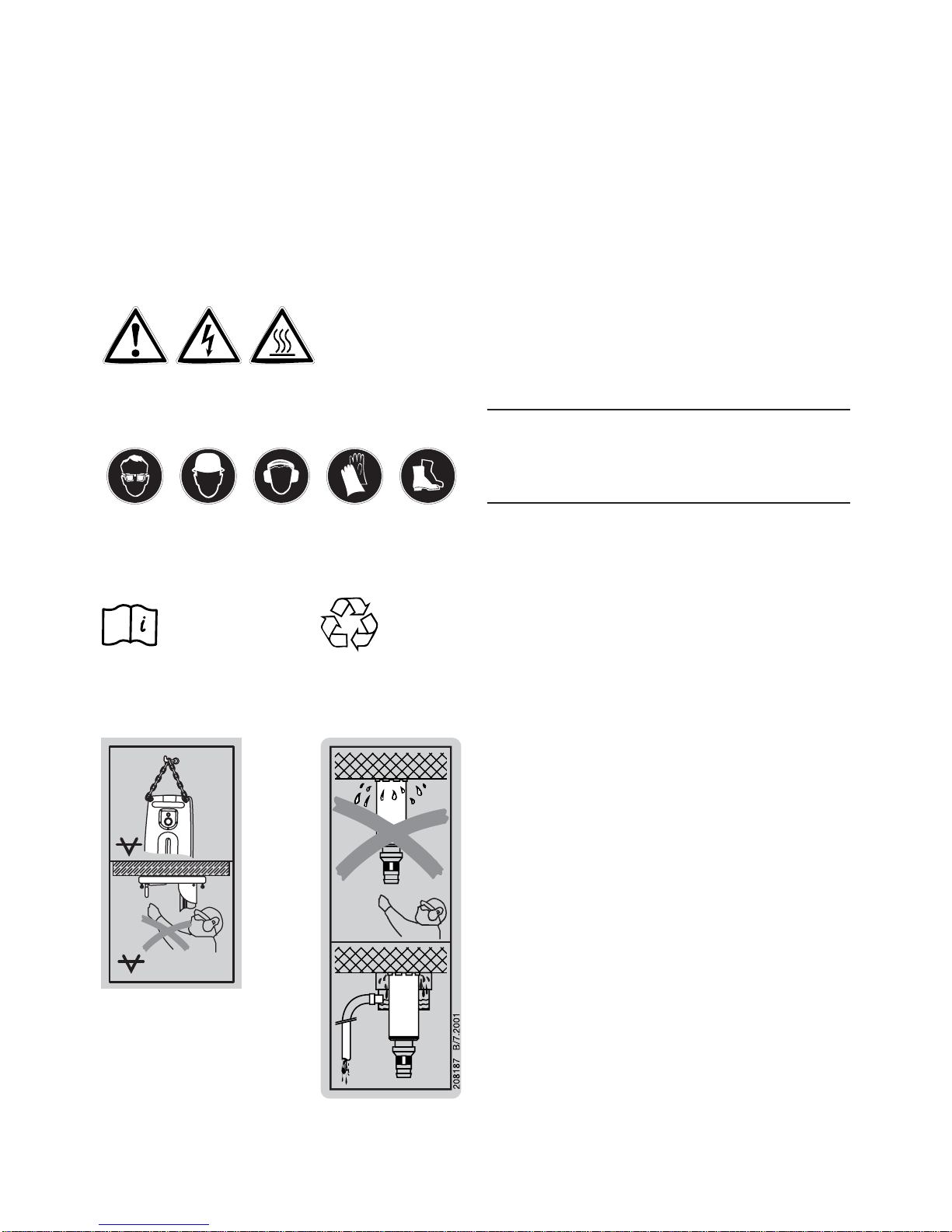
b)Use safety equipment. Always wear eye protection.
Safetyequipmentsuchas dust mask,non-skidsafe-
ty shoes, hard hat, or hearing protection used for
appropriateconditionswillreduce personal injuries.
c) Avoid accidental starting. Ensure the switch is in
the off position before plugging in.
Carrying power
tools with your finger on the switch or plugging in
powertoolsthathave the switchoninvitesaccidents.
d)Remove any adjusting key or wrench before turn-
ing the power tool on.
Awrenchora key leftattached
toarotatingpart of thepowertoolmay result in per-
sonal injury.
e) Do not overreach. Keep proper footing and balance
at all times.
Thisenables better controlof the pow-
er tool in unexpected situations.
f)Dress properly. Do not wear loose clothing or jew-
ellery. Keep your hair, clothing and gloves away
from moving parts.
Looseclothes,jewelleryorlong
hair can be caught in moving parts.
g)If devices are provided for the connection of dust
extraction and collection facilities, ensure these
are connected and properly used.
Useofthesedevices
can reduce dust related hazards.
5.1.4 Power tool use and care
a) Do not force the power tool. Use the correct power
tool for your application.
Thecorrectpowertool will
dothejobbetter and saferattherate for which itwas
designed.
b)Do not use the power tool if the switch does not turn
it on and off.
Anypowertoolthat cannot becontrolled
with the switch is dangerous and must be repaired.
c)Disconnect the plug from the power source before
makingany adjustments, changing accessories, or
storingpower tools.
Suchpreventive safety measures
reducethe risk of starting the power tool accidentally.
d)Store idle power tools out of the reach of children
and do not allow persons unfamiliar with the pow-
er tool or these instructions to operate the power
tool.
Power tools are dangerous in the hands of
untrained users.
e) Maintain power tools. Check for misalignment or
binding of moving parts, breakage of parts and any
other condition that may affect the power tool's oper-
ation. If damaged, have the power tool repaired
before use.
Many accidents are caused by poorly
maintained power tools.
f)Keep cutting tools sharp and clean.
Properlymain-
tainedcuttingtoolswith sharp cuttingedgesareless
likely to bind and are easier to control.
g)Use the power tool, accessories and tool bits etc.,
in accordance with these instructions and in the
manner intended for the particular type of power
tool, taking into account the working conditions and
the work to be performed.
Useofthepower tool for
operationsdifferentfromthose intended couldresult
in a hazardous situation.
5.1.5 Service
a) Have your power tool serviced by a qualified repair
person using only genuine replacement parts.
This
willensure that the safety of the power tool is main-
tained.
5.2 Additional safety rules
5.2.1 Personal safety
a) Wear ear protection.
Excessivenoise may leadto a
loss of hearing.
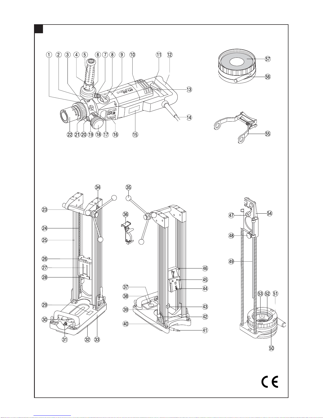
b)Use the auxiliary handle supplied with the tool.
Loss of control of the tool may lead to injury.
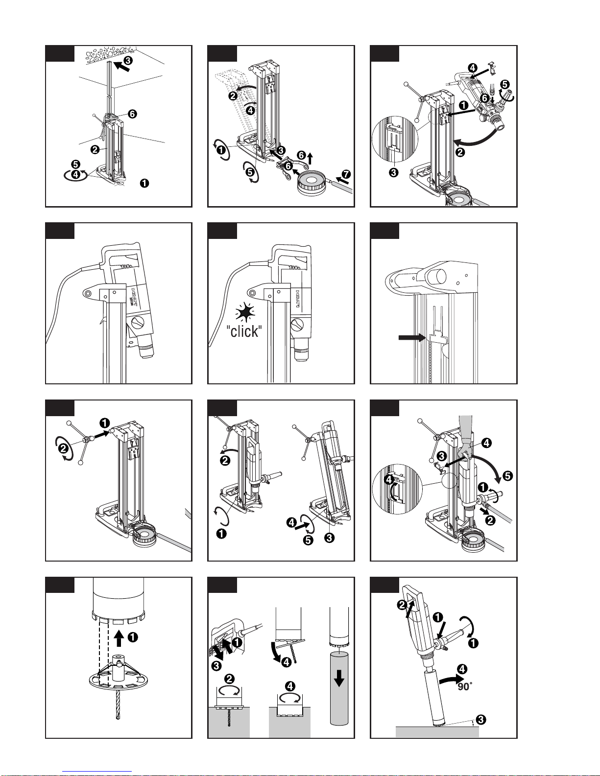
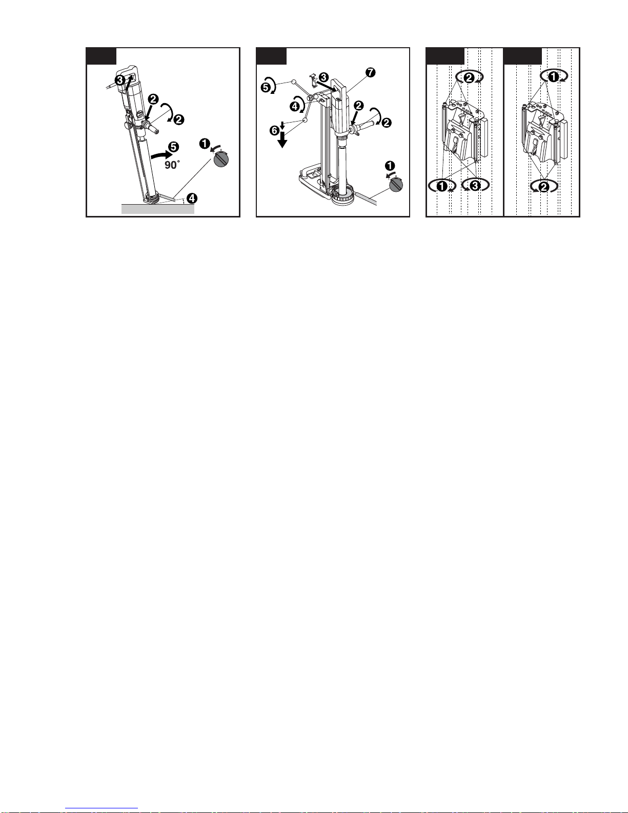
c)The tool may be operated only when held in both
hands or when mounted on the drill stand. Ensure
that the side handle is fitted correctly and tightened
securely. Always hold the tool in both hands when
it is in use.
d)Breathing protection must be worn when the tool is
used without a dust removal system for work that
creates dust.
e) To avoid tripping and falling when working, always
lead the sypply cord, extension cord and dust extrac-
tion hose away tho the rear.
f) Take care to avoid tripping over the supply cord,
extension cord or extraction hose.
g)Avoid skin contact with drilling slurry.
h)Ensure that the water swivel / extraction head (side
handle mount) is properly secured in position and
that the locking ring is tightened (see 6.1.3).
i) Ensure that the tool is securely attached when mount-
ed on the drill stand (see 6.9).
j) Do not touch rotating parts.
5.2.2 Power tool use and care
a) Ensure that the insert tools used are equipped with
the appropriate connection end system and that they
are properly fitted and secured in the chuck
.
b)In the event of a power faillure, switch the tool off
and unplug the supply cord.
Thispreventsinadver-
tent starting when the power returns.
c)Observe the instructions concerning care and main-

20
- CAUTION -
■The tool, the diamond core bit and the
drill stand are heavy.
■There is a risk of pinching parts of the
body.
■Wearasafetyhelmet,safetyglovesand
safety boots.
tenance and the replacement of core bits in good
time.
5.2.3 Electrical safety
a) Before beginning work, check the working area (e.g.
with a metal detector) to ensure that no concealed
electric cables or gas and water pipes are present.
External metal parts of the tool may become live if,
forexample,anelectric cable isdamagedinadvertenly.
This presents a serious risk of electric shock.
b)Check the condition of the supply cord and its plug
connections and have it replaced by a qualified elec-
trician if damage is found. Check the condition of
the extension cord and replace it if damage is found.
Do not touch the supply in the event of it suffering
damage while working. Disconnect the supply cord
plug from the socket
. Damaged supply cords and
extension cords present a risk of electric shock.
c) Dirty or dusty electric tools should thus be checked
at a Hilti service center at regular intervals, espe-
cially if used frequently for working on conductive
materials. Dust (especially dust from conductive
materials) or dampness adhering to the surface of
the tool may, under unfavorable conditions, present
a risk of electric shock.
d)Ensure that the tool is switched off (remove the switch
lock insert) before switching on at the PRCD (ground
fault interrupter). Test the PRCD each time before
use (see 7.1).
5.2.4 Work area
a) Ensure that the workplace is well lit.
b)Ensure that the workplace is well ventilated.
Poorlyventilatedworkplacesmay be injurioustothe
health due to exposeure to dust.
5.2.5 Personal protective equipment
Theuserandanyotherpersonsinthevicinitymustwear
suitablesafetygoggles,asafetyhelmet,earprotection,
safetyglovesandsafetybootswhilethetoolisinoper-
ation.
5.2.6 Protective equipment
Never use the tool without the applicable protective
equipment:
●Neveroperatethetoolwithoutthewaterswivel/extrac-
tion head.
●Anadditionalmeansofsecuringthedrillstandmust
beemployedwhenusedforhorizontaldrillingwithvac-
uum attachment.
●Thedrillstandmustbefastenedbymeansofananchor
orquick-releasebracewhenusedforoverheaddrilling.
●Useofthewatercollectorsysteminconjunctionwith
awet-typevacuumcleanerismandatory when carrying
out wet overhead drilling.
6. Before use
Itisessentialthatthesafetyprecautionsprintedinthese
operating instructions are read and observed.
-CAUTION-
Disconnect the tool from the mains supply.
Ifextensioncablesareused:Onlyextensioncablesofa
typeapprovedfortheintendeduseandofadequatecross
section may be used. Failure to observe this point may
resultinreducedperformance and could cause the cable
tooverheat.Damagedextensioncablesmustbereplaced.
Therecommendedcablecross-sectionsandmaximum
lengths are: Conductor cross-section
Mains voltage 1.5 mm22.0 mm22.5 mm23.5 mm2
100 V 20 m 40 m
110–120 V 20 m 40 m
220–230 V 50 m 80 m
6.1 Side handle
6.1.1 Fitting the side handle
1. Screw the side handle onto the tool and tighten it
securely.
6.1.2 Fitting the side handle in a different position
1. Remove the screw plug at the position where the side
handle is to be fitted (e.g. for left-handed use). The
grip at the end of the side handle can be unscrewed
and used as a screwdriver.
2. Screw the side handle onto the tool at the desired
position and tighten it securely.
3. Insert the screw plug in the exposed threaded hole.
6.1.3 Adjusting the extraction head / water swivel (and
side handle)
1. Press the water swivel lock out of the gap between
thelockingringandthewaterswivel/extractionhead.
2. Releasethelockingringbetweenthechuckandside
handle.

21
Note
Use only original Hilti core bits and accessories!
1. Open the chuck by turning it counter-clockwise (as
seen from the front end of the chuck).
2. Insert the diamond core bit in the chuck.
3. Push the diamond core bit into the chuck and rotate
the core bit until it engages.
4. Close the chuck by turning it clockwise (as seen from
the front end of the chuck).
5. Check that the core bit it is securely seated by grip-
pingitandattemptingtopullitawayfromthechuck.
6.3 Selecting the drilling speed (gear selector posi-
tions 1-2-3)
-CAUTION-
Do not operate the gear selector while the tool is run-
ning. Wait until rotation has stopped.
Hand-held use
278663
4
3
/
4
" - 6
1
/
2
"
2
5
/
8
" - 4
1
/
4
"
1
/
2
" - 2
1
/
2
"
I
II
III
1
5
/
8
" - 2
1
/
2
"
1
/
2
" - 1
1
/
2
"II
III
122 - 162
67 - 112
12 - 62
40 - 62
12 - 37
mm Inch
Drill-stand use
1. Select the gear according to the table on the tool.
2. Move the gear selector to the desired setting while
rotating the core bit.
6.4 Dry drilling
6.4.1 Connecting the extraction system
1. Unscrewthecoverfromthewaterswivel/extraction
head.
2. Insert the extraction hose in the extraction connec-
tion.
3. Close the water valve in the side handle.
6.5 Hand-held wet drilling
6.5.1 Connecting the water supply
1. Close the water valve in the side handle.
2. Close the cover on the dust extraction connection.
3. Connect the water supply hose (hose connector).
6.6 Hand-held wet drilling with the water collection
system
6.6.1 Fitting the water collection system
Use of the water collection system permits water to be
drainedawayfromthecorebitthusavoidingsoilingthe
surroundingarea.Bestresultsareachievedinconjunc-
tion with a wet-type vacuum cleaner.
-CAUTION-
■The core bit may become hot during
use or during sharpening.
■It may burn your hands.
■Thecuttingedges(segments)maycause
injury.
■Wearsafetygloveswhenchangingthe
core bit.
3. Move the side handle into the desired position (15°
increments).
4. Tighten the locking ring securely until the teeth and
the water swivel lock engage.
6.2 Fitting the diamond core bit

22
Use of the water collection system in conjunction with
a wet-type vacuum cleaner is mandatory for overhead
drilling.Positionthesidehandleandwaterswivel/extrac-
tionheadsothatthewatercollectionsystemcanbefit-
ted without obstruction. The centering ring and seal
mustbeofasizesuitableforthecorebitdiameterused.
1. From below the tool, position the water collection sys-
tem on the two mounting pins.
2. Swingthewatercollectionsystemtowardsthefront.
3. Secure the water collection system by turning the
knob.
4. Connect a wet-type vacuum cleaner to the front of the
water collection system. Alternatively, the water can
be allowed to flow away through a length of hose
attached to the connector (not permissible for over-
head drilling).
6.6.2 Adjusting the depth gauge
1. Set the depth gauge to the desired depth.
2. Use the clamping screw to secure the depth gauge.
6.7 Using the drill stand
6.7.1 Using an anchor (HKD-D M12) to secure the
drill stand
1. Placethe anchor at a distance of 200 mm (ideal dis-
tance) from the centre of the hole to be cored.
2. Screw the quick-release spindle into the anchor.
3. Place the drill stand over the quick-release spindle
and use the hole centre indicator to bring the drill
stand into alignment.
4. Fit the nut to the quick-release spindle but do not tight-
en it fully.
5. Thefourlevellingscrewsshouldthenbeusedtolev-
elthebaseplate.Thespiritlevelonthebaseplateserves
as a levelling aid.
6. Usethelocknutstopreventfurthermovementofthe
levelling screws.
7. Tightenthe nutssecurely with an open-end wrench.
6.7.2 Securing the drill stand with the vacuum pad
Avacuumreleasevalveisincorporatedinthebaseplate
grip.
Overhead drilling with the drill stand attached only by
vacuum is not permissible.
1. Unscrew the four levelling screws until they project
approx. 5 mm beneath the baseplate.
2. Connectthehosebetweenthevacuumconnectoron
the baseplate and the vacuum pump.
3. Switch on the vacuum pump and extend the hole
centre indicator. While pressing the vacuum release
valve and observing the hole centre indicator, bring
the baseplate into the desired position. When posi-
tioned correctly, press the baseplate against the work
surface and remove your finger from the vacuum
release valve. Before beginning drilling and during
operation, it must be ensured that the pressure gauge
pointer remains within the green area.
4. Thefourlevellingscrewsshouldthenbeusedtolev-
elthebaseplate.Thespiritlevelonthebaseplateserves
as a levelling aid.
5. Tightenthe lock nuts to prevent further movement of
the levelling screws.
6. Anadditionalmeansofsecuringthedrillstandmust
be employed when drilling horizontally (e.g. a chain
attached to an anchor, ...)
6.7.3 Securing the drill stand with a quick-release
brace (e.g. between floor and ceiling)
1. Extendtheholecentreindicatorandthenuseitasan
aidtobringthedrillstandintoalignmentwiththecen-
tre point of the hole to be cored.
2. Position the end of the quick-release brace carefully
intheinnerovalofthebaseplate(notonthelevelindi-
cator or pressure gauge).
3. Secure the baseplate by applying slight pressure with
the quick-release brace.
4. Thefourlevellingscrewsshouldthenbeusedtolev-
elthebaseplate.Thespiritlevelonthebaseplateserves
as a levelling aid.
5. Tightenthe lock nuts to prevent further movement of
the levelling screws.
6. Tighten the quick-release brace securely.
VACUUM
VACUUM

23
6.8 Water collection system for use with the drill stand
Use of the water collection system permits water to be
drainedawayfromthecorebitthusavoidingsoilingthe
surroundingarea.Bestresultsareachievedinconjunc-
tion with a wet-type vacuum cleaner.
Use of the water collection system in conjunction with
a wet-type vacuum cleaner is mandatory for overhead
drilling.Thedrillstandmustbesetupat90°tothework
surface.
The water collector sleeve and seal must be of a size
suitable for the core bit diameter used.
1. Slackenthecolumnadjustingleveruntilthelocating
lugs are disengaged.
2. Tilt the frame.
3. Fit the water collector holder.
4. Bring the frame back to the vertical position.
5. Close the adjusting levers until the locating lugs are
fully engaged and the frame is again secured.
6. Lift the holder and push the water collector cup under
the retainer as far as it will go.
7. Connectawet-typevacuumcleanertothewatercol-
lectorcuporconnectalengthofhosethroughwhich
the water can flow away.
6.9 Mounting the tool on the drill stand
-CAUTION-
Therelease lever on thedrill stand must bein the open
positionandthecarriageshouldbeatthetopofitstravel.
Thedrillingadvancemechanismmustbelocked(chain
arrestor engaged).
1. Fit the tool interfaceplateontothetwomountingpins
on the drill stand. (6.9.1)
2. Swing the tool briskly toward the drill stand. It should
be heard to engage. (6.9.2)
3. Check the position of the release lever in order to
ensurethatthetoolisengagedandattachedsecure-
ly to the drill stand. (6.9.3)
4. Inserttheswitchlockinthegripopening.Theswitch
lockisusedtoholdtheswitchintheONpositiondur-
ing sustained operation.
5. Close the water valve in the side handle.
6. Connect the water supply.
6.10 Fitting the hand wheel
1. Fit the hand wheel onto the axle.
2. Securethehandwheelbytighteningthescrewknob.
3. The hand wheel may be fitted on either side of the drill
stand.
6.11 Adjusting the drill stand drilling angle
(In increments of 7.5°; adjustable to max. 45°)
1. Slacken the column adjusting levers until the locat-
ing lugs are disengaged.
2. Bring the columns into the desired position.
3. Engage the locating lugs.
4. Move the adjusting levers until the locating lugs are
fully engaged and the frame is again secured.
5. Pressinandpivottheadjustingleverstoreturnthem
to the vertical position.
6.12 Removing the tool from the drill stand
-CAUTION-
Thetool must bedisconnected from theelectric mains
supply.
Thedrillingadvancemechanismmustbelocked(chain
arrestor engaged).
1. Close the water valve in the side handle.
2. Disconnect the water supply.
3. Remove the switch lock from the grip.
4. Hold the tool with one hand on the grip and release
the lever on the drill stand.
5. Pivot the tool away from the drill stand.
7. Operation
7.1 Connect the tool to the electric mains supply
The voltage given on the rating plate must correspond
to the voltage provided by the mains supply.
1. Check that the tool is switched off or, respectively,
remove the switch lock.
2. Insert the supply cord plug in the mains socket.
3. Press the "ON" button on the PRCD ground fault inter-
rupter (the lamp must light).
4. Press the "TEST" button on the PRCD ground fault
interrupter (the lamp must not light).
-DANGER-
If the indicator continues to light, further operation of
themachine ist not permissible. Have the machine repair-
edby a qualified specialist using genuine Hilti spare parts.
5. Press the "ON" button on the PRCD ground fault inter-
rupter (the lamp must light).
-CAUTION-
■The tool and the coring operation cre-
ate noise.
■Excessivenoisemaydamagethehear-
ing.
■Wear ear protection.
-CAUTION-
■The coring operation may cause haz-
ardous fragments to fly off.
■Flying fragments may cause injury to
the eyes or other parts of the body.
■Wear eye protection and a safety hel-
met.
7.2 Dry drilling
7.2.1 Fitting the hole-starting aid
Adifferenthole-startingaidisrequiredforeachdiamond
core bit diameter.
1. Fit the hole-starting aid into the front end of the dia-
mond core bit.

24
7.2.2 Vacuum cleaner with power socket for electric
tools
The vacuum cleaner starts automatically after switch-
ing on the electric tool. Switching off the electric tool
alsocausesthevacuumcleanertobeswitchedoffafter
a short delay.
Switching on
1. Press the on / off switch on the tool.
2. With the hole-starting aid fitted, begin drilling and
continue until the projecting segments have estab-
lished a kerf in the base material.
3. Switch the tool off.
4. Remove the hole-starting aid and continue drilling.
Switching off
1. Switch the tool off.
2. Remove the core if necessary.
7.2.3 Vacuum cleaner without power socket for elec-
tric tools
Switching on
1. Switch the vacuum cleaner on.
2. Press the on / off switch on the tool.
Switching off
1. Switch the tool off.
2. Allow the vacuum cleaner to run for a short time in
ordertoremoveremainingdustbeforeswitchingoff.
7.3 Hand-held wet drilling
Switching on
1. Openthe water valve in the side handle until the desired
water volume flows. The water flow volume can be
observed at the indicator on the hand grip.
2. Press the on / off switch
3. When starting a hole, hold the tool at a slight angle
totheworksurface. This makes hole-starting easier.
4. Once the hole has been started, bring the tool into the
90° position and continue drilling.
Switching off
1. Switch the tool off.
2. Close the water valve on the side handle.
7.4 Hand-held wet drilling using the water collection
system
The crosshair marks at the front end of the water col-
lection system serve as an accurate positioning aid.
Switching on
1. Switch on the water extraction system (if used).
2. Open the water valve on the side handle slowly until
thedesiredwatervolumeflows.Usetheindicatoron
the side handle to check the water flow rate.
3. Press the on / off switch.
4. Hold the tool at a slight angle to the work surface
when starting a hole. This makes hole-starting easi-
er.
5. After starting the hole, bring the tool into the 90° posi-
tion and continue drilling.
Switching off
1. Switch the tool off.
Caution: When drilling overhead, any water remain-
ing in the core bit must not be allowed to run down
over the tool.
2. Close the water valve on the side handle.
3. Switch off the vacuum cleaner (if used).
4. Remove the core if necessary.
7.5 Wet drilling using the drill stand
Switching on
1. Switch on the (wet) vacuum cleaner (if used).
2. Open the water valve at the side handle slowly until
the desired volume of water flows. The indicator at
the side handle can be used to check the water flow
rate.
3. Use the switch actuator to run the tool in sustained
operation mode.
4. Release the chain arrestor.
5. Bring the core bit into contact with the work surface
by turning the hand wheel.
6. Apply only slight pressure to the core bit when begin-
ningdrillingandthenincreasepressureoncethecore
bit has become centred.
7. Keep an eye on the overload indicator while drilling.
Pressureonthecorebitmustbereducediftheover-
load indicator lights.
Switching off
1. Close the water regulation valve at the side handle.
2. Pull the core bit out of the hole.
3. Engage the chain arrestor.
4. Switch the tool off.
5. Switch off the vacuum cleaner (if used).
6. Remove the core if necessary.
7. Switch the tool off.
Caution: When drilling overhead, any water remain-
ing in the core bit must not be allowed to run down
over the tool.
8. Ensurestabilityofthedrillstandbyloweringthetool
and core bit to the baseplate.
8. Care and maintenance
Disconnect the supply cord plug from the socket.
8.1 Care of core bits
Remove any dirt adhering to the core bits and protect
their surfaces from corrosion by rubbing them with an
oily cloth from time to time. Always keep the connec-
tion end clean and slightly greased.
8.2 Care of the tool
Check that the supply cord plug is disconnected.
Neveroperatethetoolifitsventilationslotsareblocked.
Cleantheventilationslotscarefullywithadry brush. Do
notallowforeignobjectstoentertheinteriorofthetool.
Cleantheoutsidesurfaces of the tool with a damp cloth

25
atregularintervals. Do not use a spray,steam cleaning
equipment or running water for cleaning. This could
negativelyaffecttheelectricalsafetyofthetool.Always
keepthegripsurfaces of the tool free from oil and grease.
Do not use cleaning agents which contain silicone.
Cleanthechuckandtheclampingsegmentswithacloth
at regular intervals and lubricate these parts with Hilti
lubricant spray. Remove any dirt and fragments from
the chuck.
Remove the filter in the water intake at the side handle
from time to time and rinse the filter sieve under run-
ningwaterinthedirectionoppositetothenormalwater
flow.
Ifthewaterflowindicatorhasbecomedirty,removeand
clean the parts. Do not use abrasive agents or sharp
objects to clean the sight glass. This may negatively
affect functionality of the water flow indicator.
8.3 Maintenance of the tool
Check all external parts of the tool for damage at regu-
lar intervals and check that all operating controls func-
tion faultlessly. Do not operate the tool when parts are
damaged or when operating controls do not function
faultlessly.ThetoolshouldberepairedataHiltiservice
centre.
Repairs to the electrical section of the tool may be car-
ried out by trained electrical specialists only.
8.4 Care of the drill stand
8.4.1 Care of the chain
Checkthechainguidestoensuretheyremaincleanand
freefromdrillingslurry.The chain must always be pro-
tected by a film of grease.
8.5 Maintenance of the drill stand
8.5.1 Adjusting the movement
Movement should be easy but without play.
The movement can be adjusted by way of screws (2 at
the top and 2 at the bottom).
8.5.1.1 Stiffer movement
1. Release the lower screw.
2. Tighten the upper screw as far as necessary.
3. Tighten the lower screw as far as it will go.
8.5.1.2 Easier movement
1. Release the upper screw.
2. Tighten the lower screw as far as it will go.
8.5.2 Adjusting the chain tension
Whenthecarriageisintheendposition,thechainshould
sag only slightly when running horizontally. Chain ten-
sioncanbeadjustedbywayoftwoscrews(chainsym-
bol on the cover).
●Turningin a clockwise direction increases chain ten-
sion.
●Turning in a counter-clockwise direction decreases
chain tension.
Both chains must be tensioned equally.

26
9. Troubleshooting
Fault Possible cause Remedy
The tool doesn't start. Fault in mains supply Plug in another electric appliance
and check whether it works.
Supply cord or plug defective The cord should be checked and
replaced if necessary by an
electrical specialist.
Switch defective The switch should be checked and
replaced if necessary by an
electrical specialist.
Motor runs but the core bit Gearing defective The tool should be repaired at a
doesn't rotate. Hilti service centre.
Rate of drilling progress decreases. Water pressure / water flow rate too Regulate the water flow rate at the
high side handle.
Core bit defective Check the core bit for damage and
replace it if necessary.
Gearing defective The tool should be repaired at a
Hilti service centre.
Core bit segments polished Resharpen the core bit on a sharp-
ening plate under water flow.
Motor cuts out. Tool stops running. Guide the tool straight.
Tool has overheated. The motor's Ease the load on the tool and allow
thermal overload protection has been it to run up to full speed by press-
activated. ing the switch several times.
Electronics defective The tool should be repaired at a
Hilti service centre.
Cooling fan defective The tool should be repaired at a
Hilti service centre.
Water does not flow. Filter or water flow indicator blocked Remove the filter or water flow
indicator and flush it through.
Water escapes at the gear housing. Shaft seal / water swivel / extraction The tool should be repaired at a
head defective Hilti service centre.
The core bit cannot be inserted in Connection end or chuck dirty or Clean the connection end and
the chuck. damaged chuck. Replace parts if necessary.
Water escapes at the chuck. Connection end or chuck dirty Clean the connection end and
chuck.
Chuck seal defective Check the seal and replace it if
necessary.
Excessive play in the drilling Excessive play at the guides Readjust the guides.
system. Chain inadequately tensioned Tension the chain.
Pivot mechanism loose Tighten the pivot mechanism
adjusting lever (6.11).

27
10. Disposal
Most of the materials from which Hilti pow-
er tools are manufactured can be recycled.
The materials must be correctly separated
before they can be recycled. In many coun-
tries, Hilti has already made arrangements for taking
back your old electric tools for recycling. Please ask
your Hilti customer service department or Hilti sales
representative for further information.
Disposal of drilling slurry
With regard to environmental aspects, allowing drilling
slurry to flow directly into rivers, lakes or the sewer-
age system without suitable pre-treatment is prob-
lematical. Ask the local authorities for information about
applicable regulations.
We recommend the following pre-treatment:
Collect the drilling slurry (e.g. use a wet-type indus-
trial vacuum cleaner).
Allow the slurry to settle and dispose of the solid mate-
rial at a construction waste disposal site (the addition
of a flocculent may accelerate the settling process).
Water from the drilling slurry (alkaline, ph value > 7)
should be neutralized by adding an acidic neutralizing
agent or large quantity of water before it is allowed to
flow into the sewerage system.
Only for EU countries
Disposalofelectrictoolstogetherwithhouseholdwaste
is not permissible!
In observance of European Directive 2002/96/EC on
wasteelectricalandelectronicequipmentanditsimple-
mentationinaccordancewithnationallaw,electric tools
thathavereachedtheendoftheirlifemustbecollected
separatelyandreturnedtoanenvironmentallycompat-
ible recycling facility.
11. Manufacturer's warranty – tools
Hilti warrants that the tool supplied is free of defects
in material and workmanship. This warranty is valid so
long as the tool is operated and handled correctly,
cleaned and serviced properly and in accordance with
the Hilti Operating Instructions, and the technical sys-
tem is maintained. This means that only original Hilti
consumables, components and spare parts may be
used in the tool.
This warranty provides the free-of-charge repair or
replacement of defective parts only over the entire lifes-
pan of the tool. Parts requiring repair or replacement
as a result of normal wear and tear are not covered by
this warranty.
Additional claims are excluded, unless stringent
national rules prohibit such exclusion. In particular,
Hilti is not obligated for direct, indirect, incidental
or consequential damages, losses or expenses in
connection with, or by reason of, the use of, or inabil-
ity to use the tool for any purpose. Implied warranties
of merchantability or fitness for a particular purpose
are specifically excluded.
For repair or replacement, send tool or related parts
immediately upon discovery of the defect to the address
of the local Hilti marketing organization provided.
This constitutes Hilti's entire obligation with regard to
warranty and supersedes all prior or contemporane-
ous comments and oral or written agreements con-
cerning warranties.
12. EC declaration of conformity
Designation: Diamond drilling machine
Type: DD130
Year of design: 2001
Wedeclare, on our sole responsibility, that this product
complies with the following directives and standards:
98/37/EC, 89/336/EEC, EN 61029-1, EN 55014-1, EN
55014-2, EN 61000-3-2, EN 61000-3-11
Hilti Corporation
Peter Cavada Ivo Celi
Head of BU Head of BU
Quality and Process Management Diamond
BA Electric Tools & Accessories
05/2007 05/2007

Hilti Corporation
FL-9494 Schaan
Tel.:+423/2342111
Fax: +423/2342965
www.hilti.com
Hilti = registered trademark of Hilti Corp., Schaan W 2690 0707 10-Pos. 1 1 Printed in Liechtenstein © 2007
Right of technical and programme changes reserved S. E. & O.
370458/G
*370458*
Other manuals for DD 130
2
Table of contents
Other Hilti Drill manuals

Hilti
Hilti UD16 User manual

Hilti
Hilti UH 240-A User manual

Hilti
Hilti TE 7-A User manual

Hilti
Hilti SFC 14-A User manual

Hilti
Hilti SFD 22-A User manual

Hilti
Hilti DD 120 User manual

Hilti
Hilti SIW 22T-A 1/2 inch User manual

Hilti
Hilti UD16 User manual

Hilti
Hilti NURON DGH 130-22 User manual

Hilti
Hilti TE15 User manual

Hilti
Hilti NURON SF 6-22 User manual

Hilti
Hilti NURON SF 8M-22 User manual

Hilti
Hilti SFD 2-A12 User manual

Hilti
Hilti TE 3-ML User manual

Hilti
Hilti SF 2-A User manual

Hilti
Hilti DD 350-CA User manual

Hilti
Hilti SF 14-A User manual

Hilti
Hilti NURON SF 10W 22 User manual

Hilti
Hilti SF 10W-A22 User manual

Hilti
Hilti SF 10W-A22 User manual