4 English 2124682 *2124682*
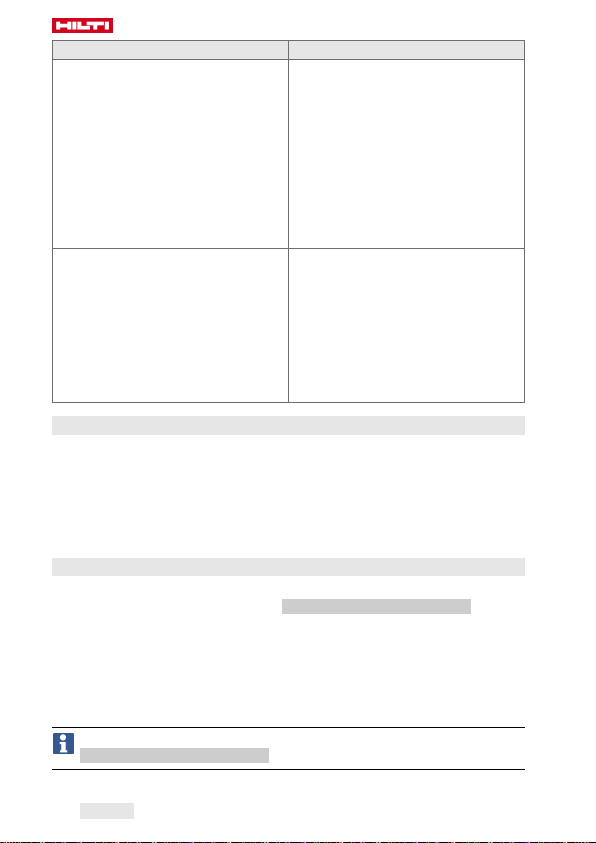
Status Meaning
The LEDs flash red. • When scanning: the barcode or
QR code was not recognized.
• When tightening, after the im-
pact wrench switches off: The
threaded fastener could not be
tightened in accordance with the
selected settings. The reason for
this could be, for example, that
the impact wrench was switched
off manually before the correct
torque was achieved.
The LEDs flash yellow. • The module detected that the
threaded fastener had been tight-
ened and subsequently slack-
ened. Consequently, the threaded
fastener has been retightened in
accordance with defined param-
eters for retightening, and the
tightening operation has been
completed successfully.
3.6 Buzzer
The buzzer in the adaptive torque module emits the following signal tones
as audible feedback:
• Long buzz: Confirmation signal (OK / operation completed successfully)
• 2 short buzzes, the LEDs flash yellow: Warning 1 (OK or, as applicable,
not OK / repeat tightening)
• 4 short buzzes, the LEDs flash red: Warning 2 (not OK / operation aborted)
3.7 USB connection
The USB port can be used to connect the adaptive torque module to a PC.
When this connection is made, the AT Documentation Software offers a
range of functions, including:
• Adding new data records for new fasteners
• Changing / updating existing data records
• Deactivating / activating the documentation function
• Loading the log from the documentation function
• Setting the clock in the torque module
Further information can be found in the documentation for the
AT Documentation Software.