4 5
Once the connections have been completed, insert the two wires with a faston connector coming
from the power supply to the battery, respecting the connection polarity.
Red = [+] battery positive / Black = [-] negative battery.
After connecting the battery of the control panel and the siren, the system can be switched on using
the disconnector connected to the power supply. The NETWORK LED on the panel of the control unit
stops flashing and remains steady to indicate the effective presence of the mains voltage.
For safety reasons and for compliance with the regulations in force, it is advisable to make and check the
connection to the ground system to all the devices that need it..
6 - 7
(V) = green LED (R) = red LED
1
18
2
25 Self-protective tamper.
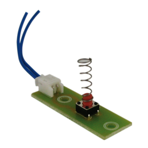
26 SETUP button.
(in case of loss of the access codes to the control unit, by pressing the "SETUP"
button for about 12 seconds, the control unit will be reset .. A beep will signal the
successful operation).
For a correct installation, it is advisable to follow the instructions on the following pages.
2.3 Connections
1 (Fuse 1) 1Afuse for external power supply.
2 (Fuse 2) 1Afuse for siren outputs.
3 SIM CARD connector.
4 GSM antenna socket
5 - 6 12Vdc voltage output fixed for external devices power supply (max 1Ah).
12Vdc voltage output for enabling external equipment active on the system
installed or on command.
8 - 9 Connection for XM Series remote consoles.
10 - 11 12Vdc output for self-powered external sirens.
11 - 12 12Vdc output in alarm condition for additional internal sirens. 12Vdc outputs for
LEDs of control systems such as PX, SK, KB.
14 Input / disarm command pulse input.
6 - 19 - 22 Common clamps for zones
- 20 -21 - 23 Lines of NC (logical) or balanced (immediate) zones.
4 Anti-tampering zone line "24h" NC logic or balanced.
15 - 17 Lines of NC delayed or balanced logic zones.
WARNING
The battery must always be connected so that he system can function properly.
It is advisable to periodically check its efficiency by measuring the voltage on the two contacts after
disconnecting the mains power supply through the appropriate disconnector (magnetothermic
switch). If the voltage tends to drop significantly even in the presence of only the central load, it is
necessary to replace it.
WARNING
The 230V ~ mains voltage must be connected to the power supply / battery charger by two
double-insulated conductors of 1.5mm^2 coming from a disconnector (eg a thermal magnetic
circuit breaker) used exclusively for the burglar alarm control unit. Inside the control unit,
position the two conductors in a sufficiently tidy manner, locking them by means of the supplied
cable gland and possibly by means of cable ties..
2 Installation
2.1 Avvertenze generali
!Do not install this central unit in places subject to extreme temperatures and/or bad weather;
!For a solid and secure fixing it is advisable to make sure that the mounting surface is flat. Position the
central unit at a height that allows easy access to the front panel.
!The connections must be carried out in compliance with CEI 79-3-2012 "Special regulations for
burglar-proof, intrusion, alarm and anti-aggression systems".
2.2 Power Supply
The power supply to the entire system is supplied by the power supply unit-battery charger inside the
control unit, which constantly keeps the battery charged (B12V7,5Ah).
Installation
+Rif
220V
12V
Power Supply
230V~
50Hz
Power Gap
Red
White
Black
Battery 12V
RETE
ALLARME
USCITA
ZONA
1
ZONA
2
ZONA
3
ZONA
4
ZONA
5
ZONA
6
ZONA
24h
1
4
7
2
5
8
3
6
9ESC
0
GSM
MEMORIA
STATO
tuv wxyzpqrs OFFON
jkl mnoghi
abc def
mic
AL35SW
Red
Black
6 zone GSM
security security
12
3 4 5 6 7 8910 11 13 14 15 16 17 18
+12V +INT AB S.A. GND Sir. V R Key GND Z2Z1 Z3 GND Z5 GNDZ4 Z6 24H
SIM
MODULO
GSM
19 20 21 22 23 24
12
SETUP
25 26
Insert the SIM Card inside the module
taking account of the beveled corner.
PROTEC6GSM/TM600GSM - User manual
