Hiniker 703 User manual

PICKUP TRUCK SNOWPLOW
Models 703, 753, 703SS, 753SS
OPERATOR’S MANUAL
DO NOT USE OR OPERATE THIS EQUIPMENT UNTIL THIS MANUAL
HAS BEEN READ AND THOROUGHLY UNDERSTOOD
PART NUMBER 25014773
Please visit www.snowplows.hiniker.com to access the most recent version


TABLE OF CONTENTS
TO THE PURCHASER.................................................................................................................. 2
SAFETY......................................................................................................................................... 3
OPERATING PROCEDURES ....................................................................................................... 4
Table of Contents 1
25014773 7/2023 Hiniker/25014773
HEADLAMP AIMING PROCEDURE ............................................................................................. 9
CONTROLLER CONFIGURATION ............................................................................................. 10
MAINTENANCE ...........................................................................................................................11
TROUBLE SHOOTING ............................................................................................................... 13
WARRANTY ................................................................................................................................ 15
This product is designed and manufactured to
give years of dependable service when properly
maintained and used for the purpose for which it
is intended. Never allow anyone to operate this
equipment until they fully understand the complete
contents of this manual. It is the responsibility
of owners who do not operate this equipment to
ensure the operator is properly instructed and
understands the contents of this manual. It is also
the owner’s responsibility to ensure that anyone
operating this equipment is mentally and physically
capable of so doing.
Important information is contained in this manual
to help ensure safe and effi cient operation.
If you have any questions about this manual, or the
equipment discussed herein, contact your Hiniker
dealer.
TAKE NOTE! THIS SAFETY ALERT
SYMBOL FOUND THROUGHOUT THIS
MANUAL IS USED TO CALL YOUR
ATTENTION TO INSTRUCTIONS INVOLVING
YOUR PERSONAL SAFETY AND THE SAFETY
OF OTHERS. FAILURE TO FOLLOW THESE
INSTRUCTIONS CAN RESULT IN INJURY OR
DEATH.
THIS SYMBOL MEANS:
- ATTENTION!
- BECOME ALERT!
- YOUR SAFETY IS INVOLVED!
SAFETY SIGNAL WORDS:
DANGER: Indicates an imminently hazardous
situation that, if not avoided, will result in death or
serious injury.
WARNING: Indicates a potentially hazardous
situation that, if not avoided, could result in death
or serious injury.
CAUTION: Indicates a potentially hazardous
situation that, if not avoided, may result in minor or
moderate injury, or damage to components.
NOTE: Addresses safety practices not related to
personal safety.
All references to Left or Right are de ned as
viewing the plow from the cab of the truck.
TO THE PURCHASER
Instructions for raising and lowering the plow refer to
the joystick controller as received from the factory.
The raise and lower functions may be reversed to
suit the preference of the operator by following the
instructions in the Controller Con guration section.
This Operator’s Manual is shipped with this
equipment. For additional copies contact your
Hiniker dealer or visit www.snowplows.hiniker.
com.
Always obtain original Hiniker service parts.
Substitute parts could adversely a ect equipment
performance and warranty.
Check that your dealer has forwarded the
Hiniker delivery report form along with the plow
identi cation number because it helps maintain
maximum service and warranty bene ts. This does
not put you on any mailing list, and information
thereon is not available to others.
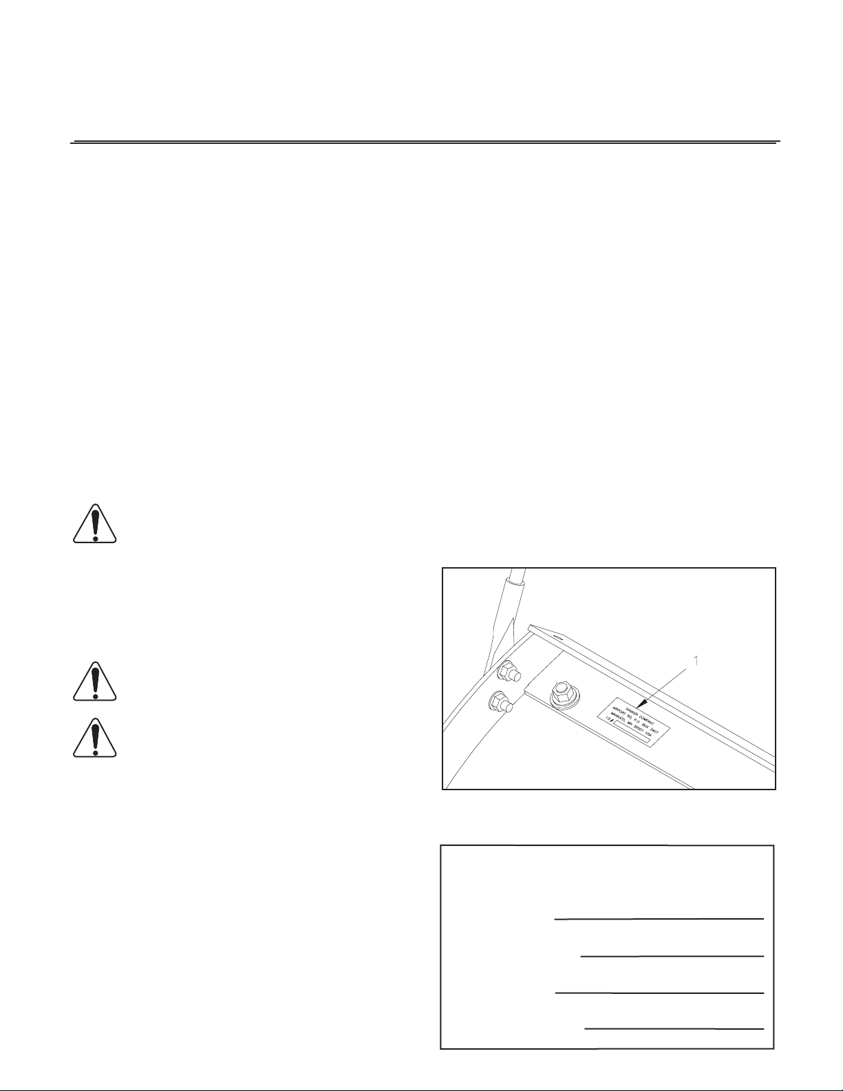
Your plow’s identi cation number plate is at
location (1) in the following illustration.
DWG NO. 5689
Record the following information for later
reference when obtaining service parts:
Purchase Date
Purchaser’s Name
Dealer’s Name
Machine I.D. No.
2 To The Purchaser

SAFETY
BEFORE OPERATION
1. Discipline yourself to visually check for
worn, damaged or cracked parts before
starting use. Replace these with genuine
Hiniker parts.
2. Escaping hydraulic oil under pressure can
penetrate the skin, causing serious injury.
Do not use your hand to check for leaks.
Use a piece of paper or cardboard to find
suspected leaks. Tighten all connections
before pressurizing hydraulic lines.
If fluid is injected into the skin, get medical
attention immediately to prevent serious
infection.
3. Check all controls and operating functions
of the machine in a safe area before starting
to work.
DURING OPERATION
1. Always wear seat belts when operating a
motor vehicle.
2. Ensure everyone is clear of the machine,
especially away from blind areas of
the operator, before starting, actuating
hydraulics or operating this equipment.
3. Do not plow snow at excessively high
speeds.
4. Avoid hitting objects that will damage your
plow or truck.
5. Set the brakes and stop the truck’s engine
before adjusting or servicing your plow.
AFTER OPERATION
1. Park the plow on a solid, level surface.
Fully collapse the lift cylinder and use the
stop plate, as described in the Operating
Procedures Removing The Plow section,
before unhitching the plow to prevent the
frame from falling forward.
This is a safety alert symbol. It alerts
an operator to information concerning
personal safety. Always observe
and heed these symbols and instructions,
otherwise death or serious injury can result.
Operator safety is a principle concern in
equipment design and distribution. However,
many accidents occur because a few seconds
of thought, and a more careful approach to
handling, were ignored.
Accidents can be avoided by knowing and
following the precautions cited in this manual.
GENERAL SAFETY
1. Read this manual thoroughly. Make sure
the operator understands it and knows
how to operate this equipment safely. This
equipment can kill or injure an untrained or
careless operator and bystanders. If you
sell this equipment, ensure the new owner
acknowledges receipt of this manual.
2. This plow is intended for plowing snow only.
Plowing gravel, rocks, etc., or using the
plow for any purpose other than plowing
snow could result in harm to the operator
or bystanders or cause damage to the plow
or vehicle, and will void the warranty.
3. Do not service or otherwise handle a plow
in the raised position unless it is securely
blocked against unexpected falling.
4. Do not attempt to handle or service this
equipment, or direct others to do the same,
unless you know how to do it safely and
have the proper tools for the job.
5. Keep hands, feet, hair, and clothing away
from moving parts.
6. Do not alter the equipment to the extent of
compromising safety or performance.
Safety 3
OPERATING PROCEDURES
4 Operating Procedures
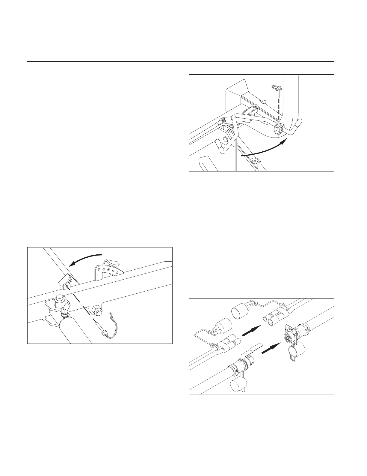
Handle Pinned With Plow On Truck DWG NO. 5691
Pin the handle in the clevis with its klik pin.
Failure to pin the handle in place may allow the
plow to fall off the truck.
NOTE: Before connecting the plow’s wiring to
the truck, make sure power is switched “Off” on
the joystick controller.
Plug in the two electrical connectors between
the plow and the truck after latching the plow.
The alignment tab on the 16-pin plug will mate
with the slot on the mating receptacle to ensure
proper connection.
Alignment Tab and Slot DWG NO. 6697
ATTACHING THE PLOW
Attachment prongs on the truck should be
mounted such that the bottom edge of the prongs
measure about 10“ above the ground. Prong
receivers on the plow frame should remain
parallel to the ground and at the correct height
by fully retracting the lift cylinder with the upper
lift links and bracing the frame with the stop
plate before removing the plow from the truck
(See “Removing the Plow”). Ideally, the prongs
on the truck should lift the plow frame slightly
when driving into the plow for attachment.
Powdered graphite applied on the prongs will
help the plow slide on and off more easily.
Check that prongs are in line with the receivers
before slowly driving into the plow. Set the
parking brake in the truck to prevent it from
creeping back out from the receivers.
DWG NO. 5690
Remove the tab lock pin from the indexing
hole and raise the parking stand to its highest
position. Repin the stand lever to the front hole
in the push frame for transport.
Pull the latch handle into the clevis on the lift
frame to force the sliders through the notches
in the prongs and receivers. Check that both
sliders are fully engaged.

Operating Procedures 5
Activate high beam/low beam and turn signal/
parking lamps from the truck as you normally
would without the plow attached.
NOTE: When removing the plow, remember to
place the headlight switch in the “truck” position to
return power to the truck’s headlights.
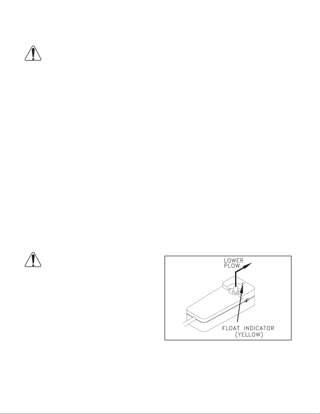
Raise or lower the plow by moving the joystick to
the “raise” or “lower” position.
Hold the plow at an intermediate height by
releasing the controller from the “raise” position
when the plow reaches the desired height.
Moving the controller to the “lower” position will
lower the blade to the ground and allow the plow
to “oat” along the contour of the ground while
plowing snow.
A yellow light on the control box indicates the
plow is in the oat mode. Momentarily moving the
joystick to the “raise” position will remove the plow
from the oat condition and the yellow indicator will
return to green.
Move the joystick left or right to angle the blade.
Release the joystick when the blade is at the
desired angle.
TRANSPORTING THE PLOW
The extra weight of the snowplow on your truck
will impair handling response and increase braking
distance. The plow will also block some airow to
the vehicle’s cooling system, possibly causing the
vehicle to overheat. Therefore, it is important not
to exceed speeds above 45 mph when the plow is
attached.
Remove the plow if you must drive your truck for
long distances when the temperature is warm.
Raise the blade to a position where it will not
interfere with the headlights before driving.
Transport the plow with power to the joystick
control box switched o to prevent accidental
lowering of the plow.
Never adjust the blade height or angle the blade
while driving.
Check that the plow headlamps and turn signals
are operational, and headlamps are aimed
correctly. Test the lift and angling cylinders in a
safe area before using the plow.
To make alignment of the plow easier in the future,
mark a point on the back of the headlamp, a point
on the hood near the front of the truck and a point
on the windshield that are in line when you are
seated behind the steering wheel. Line up these
three points when driving into the plow.
THE JOYSTICK CONTROLLER
The joystick control box has slide switches for
controlling power to the snowplow and for switching
from the truck headlights to the headlights on the
plow.
The joystick controller raises and lowers the plow
and angles the blade left or right.
NOTE: Drawings 4176 and 4177 show the raise
and lower functions of the joystick controller as
received from the factory. Functions may be
reversed to suit the preference of the operator
by following the instructions in the Controller
Conguration section for switching the controller
joystick and face plate.
The vehicle’s electrical power must be turned on
before the control box will function.
Joystick Control Box DWG NO. 4176
Place the on/o switch on the joystick control box in
the “on” position to supply power to the snowplow.
A green light will indicate power is on.
Move the headlight slide switch on the control box
to the “plow” position to change from the truck
lights to the snowplow lights.
PLOWING SNOW
WARNING: Always wear a seat belt
when plowing snow. Sudden contact
with a hidden object can result in
serious personal injury.
Inspect areas to be plowed before snowfall for
potential hazards, and mark obstructions with
stakes that will be seen when snow covers the
ground. Identify any emergency equipment and
utility outlets that may need to be cleared in the
event of a storm. Prepare a plan beforehand for
clearing snow from tight or enclosed areas and
locate sites for stacking snow.
When using skid shoes on the back of the
moldboard, adjust the skids according to the
surface to be plowed. The bottom of the skids
should be about 1/2” below the cutting edge
when plowing gravel roads or lots. Skids should
be even with the cutting edge on hard surfaces
such as asphalt or concrete.
Always plow snow as it is accumulating. Wet
snow may weigh about 12 lbs per cubic foot.
The weight of snow being pushed by your plow
may increase to several tons.
Allowing snow depth to grow to unmanageable
levels can cause difficult removal problems and
can be costly in terms of wear on equipment.
WARNING: Serious personal injury
can result from plowing at excessive
speeds, as well as costly damage to
equipment and property, if an obstruction is
encountered while plowing. Do not exceed
10 mph while plowing.
Plow snow in the lowest truck gear to transfer
maximum power to the cutting edge. Clear
areas in front of buildings first. Back drag snow
away from buildings by driving to the building
with the plow raised, then dropping the blade to
pull snow away from buildings.
Clear large lots by angling the blade and
creating a single path. Roll snow to outer edges
of the lot by taking successive passes with the
blade angled.
When plowing very deep snow, it may be
necessarytoraisethebladeandshearofflayersof
6 Operating Procedures
snow until a working area is cleared. Work small
areas in multiple passes to push snow to outer
edges. Generally, 6” snow can be plowed with
the entire blade width; 9” snow with 3/4 of the
blade width; 12” snow with 1/2 of the blade width.
Local conditions will determine how much work
can be done before stalling or getting stuck.
PARKING
Lower the plow to the ground when parking
your truck for a long period of time with the
plow attached. Place the on/off switch in the
“off” position to prevent the plow from drawing
power from the truck battery. The plow’s power
unit may continue to draw electrical current from
the truck battery if the control switch is left on;
possibly resulting in insufficient charge to start
the truck.
REMOVING THE PLOW
To remove the snowplow from your truck, park
on a solid level surface with the blade straight
across the truck. Lower the plow to the ground
and leave the controller in the “float” mode.
NOTE: The plow control box must be in the
“float” mode to manually retract the lift cylinder
rod. If the cylinder rod cannot be retracted with
power on and the controller in float, loosen the
packing nut on the lift cylinder up to 1 1/2 turns
to reduce friction.
Lower Plow, Leave Controller in “Float” DWG NO. 4177
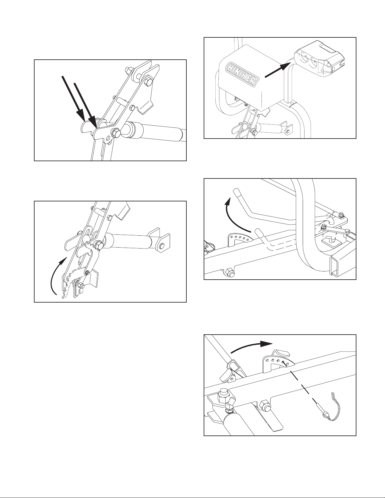
At the front of the truck, push down on the
upper lift links to fully retract the lift cylinder rod.
Retracting the lift cylinder will orient the prong
receivers correctly for reattaching the plow later
Failure to retract the lift cylinder rod will allow
Operating Procedures 7
Push Lift Frame Back DWG NO. 6005A
Swing the latch handle open until the sliders are
fully removed from the attachment prongs.
Swing Handle to Remove Sliders DWG NO. 5694
Lower the parking stand to the ground by
removing the tab lock pin from the front hole in
the push frame, then swinging the stand to the
ground with the lever.
Lower and Pin Parking Stand DWG NO. 5696
Reinstall the pin through matching holes in the
stand lever and push frame to hold the stand in
place.
the lift frame to fall forward, possibly causing
personal injury or damage to plow components.
Retract Cylinder With Upper Lift Links DWG NO. 5693
Rotate the stop plate up to contact the spacer
bushing on the lift cylinder bolt.
Rotate Stop Plate DWG NO. 5695
Gently push back on the headlight bracket to tilt
the lift frame back as far as possible, then release
the bracket to allow the weight of the lift frame to
lock the stop plate in place.
8 Operating Procedures
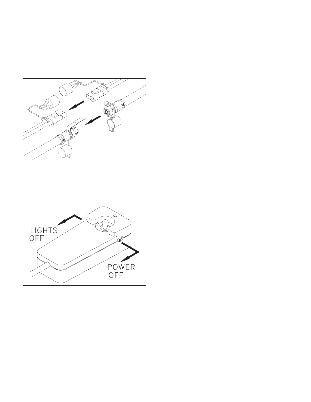
Disconnect the two electrical connectors by
pulling them straight out from the receptacles.
Do not twist the connectors. Twisting will damage
the connector pins or the wiring harness.
Place dust caps on connectors to prevent
contamination.
Disconnect Plugs DWG NO. 6698
Back inside the truck, return control of the
headlights to the truck and switch power o on
the snowplow control box, then slowly back the
truck out from the plow.
Turn Off Lights and Power DWG NO. 4178
NOTE: The stop plate will automatically fall
forward as soon as the lift cylinder is fully extended
for raising the blade prior to transporting the plow.
If the snowplow won’t be used for an extended
period of time, the prong weldment can be
removed from the truck by removing the hex bolts
that fasten it to the truck mount frame.
HEADLAMP AIMING PROCEDURE
NOTE: Headlamp aiming should be done while
plow is in a raised position.
NOTE: This procedure should be done with no
load on the vehicle other than the driver, snow-
plow, and rear ballast weight, inspect the vehicle
for proper tire in ation and broken or sagging sus-
pension components. Check functioning of any
automatic vehicle leveling systems and any spe-
ci c manufacturer’s instructions pertaining to ve-
hicle preparation for headlamp aiming. Stabilize
the suspension by rocking the vehicle sideways.
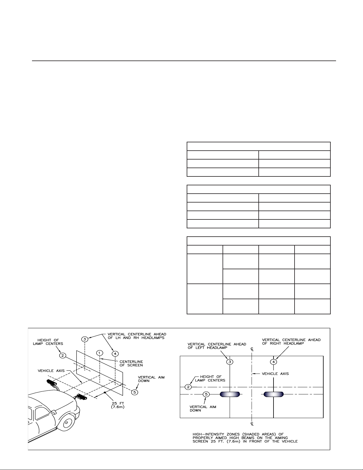
1. Park the vehicle with the plow attached on
a level surface 25’ (7.6 m) from a at, unob-
structed light-colored wall.
1. Centerline of vehicle.
2. Height of Lamp Centers.
3. LH Headlight Center (see Table 1 for di-
mensions from Line 1).
4. RH Headlight Center (see Table 1 for di-
mensions from Line 1).
5. Vertical Aim Down Height (see Table 2
for dimension from Line 2)
2. Mark the wall with black tape according to
drawing 5698B.
3. Wipe the lamp lenses clean and check for
proper switching and function.
4. Activate the plow lamp HIGH beams to illumi-
nate toward the wall.
5. Focus the center of the LH light beam on the
intersections of lines 3 and 5.
6. Focus the center of the RH light beam on the
intersections of lines 4 and 5.
7. Tighten the headlamp hardware according to
the table below.
Table 1: Lines 3 & 4 Dimensions
Type Line 3 & 4 Dimension
LED 19 in (48 cm)
Halogen 22 in (56 cm)
Table 2: Line Dimension
Height from Ground Dimension
22 to 36 in (56 to 90 cm) 0
36 to 48 in (90 to 120 cm) 2 in (5 cm)
48 to 54 in (120 to 140 cm) 4 in (6.4 cm)
Table 3: Hardware Torque
Type Size Ft-Lbs N-m
LED 1/2” (Bracket
to Bar)
58-82 79-112
1/4” (Light to
Bracket)
6-7 8-10
Halogen 1/2” (Bracket
to Bar)
58-82 79-112
3/8” (Light to
Bracket)
29-41 39-56
DWG NO. 5698B
Headlamp Aiming Procedure 9

CONTROLLER CONFIGURATION
NOTE: The 2 pin power cable and 16 pin plow har-
ness must be connected, and the vehicle’s ignition
switch must be switched on in order to test the
functions of the headlights and power unit.
1. Ensure the black and white 12 pin connec-
tor from the cab harness is attached to the
controller.
2. Use the plow selection switch to select
whether you have a V-Plow or a Straight
Blade.
NOTE: As supplied from the factory, the snow-
plow controller raises the plow when the joystick
is pulled backward and lowers the plow when
the joystick is pushed forward. If you wish to re-
vers this follow steps 3 through 5. If not, skip to
step 6.
DWG. NO. 8006
3. Pry the face plate of the controller by insert-
ing a small screwdriver along the side of the
plate of the plate at location 1 in drawing
5855A. Flip the plate over, then reinstall by
gently sliding the 4 tabs into the slots in the
controller top.
4. To reverse the joystick switch, gently pull on
the edges of the small circuit board at the
base of the joystick switch to remove the
switch from the 5 pins on the main circuit
board.
5. Rotate the switch 90 degrees then gently
push the switch back onto the 5 pins.
6. Insert the main circuit board into the case
top ensuring the joystick is properly seated
and the harness strain relief is inside the
case.
7. Assemble the case with the 4 screws.
8. Test the controller on the snow plow to ver-
ify that raise and lower functions are what
the operator desires.
DWG. NO. 5855A
Model Plow Type Postion
9585, 9595 Torsion V Up
9863, 9963, 9710 Compression V Up
2754, 2804, 2854 Steel Straight Down
8804, 8904 CDown
6814, 6914 Scoop Down
7814, 7914 Poly Straight Down
703, 753 Mid Size Straight Down
10 Controller Configuration

MAINTENANCE
WARNING: Do not service or otherwise
handle a plow in the raised position
unless it is securely blocked against
unexpected falling.
Dependable snowplow operation is the result
of following good maintenance procedures.
Inspect your plow frequently to ensure that
all parts are working smoothly, and develop a
schedule for maintenance at required intervals.
GENERAL
Wash salt and dirt off the plow before storage.
Do not power wash hydraulic cylinders, as high
pressure can damage seals and cause cylinder
failure. Touch-up any chips or scratches in the
paint and apply a light coating of grease to
extended cylinder rods to prevent corrosion.
HYDRAULIC SYSTEM
The majority of snowplow operational problems
are caused by bad oil in the hydraulic system.
Hydraulic oil should be changed every year for
best performance. Select Hiniker Cold Flow
Hydraulic Oil, or an equivalent oil that meets
military specification 5606, for plowing in
extremely cold temperatures.
To change hydraulic oil, disconnect the electrical
wiring harnesses from the snowplow power unit
and uncouple three hydraulic lines. Unbolt the
power unit from the plow, and remove it to a
clean working area that can capture any spilled
oil.
Carefully unbolt the oil reservoir from the power
unit and discard old oil. Purge old oil from the
angling cylinders by forcing rods to retract.
Clean the suction filter at the pump inlet and
wipe any metal shavings off the magnet on the
pump.
Re-attach the reservoir onto the power unit and
re-connect the power unit on the snowplow
before adding new hydraulic oil.
Re-attach hydraulic hoses and electrical wires
at the correct locations on the power unit.
Pour hydraulic oil into the power unit reservoir
until the reservoir is half full. Angle the plow full
left or right to fill the angling cylinder with oil,
then add more oil until the reservoir is about 3/4
full. Do not overfill the oil reservoir.
Cycle the plow left and right and up and down to
purge any air trapped in the hydraulic system.
Check the oil level with the plow on the ground.
Add oil to the fill line, if necessary, but do not
over fill the reservoir.
ELECTRICAL MAINTENANCE
Periodically check all electrical connections for
proper fit and remove any contamination that
may be present.
To prevent contamination always place dust caps
on connectors when not in use. This is particularly
important when the plow is being stored. The
use of dielectric grease is recommended to
reduce corrosion of the contacts and to make
connecting and disconnecting easier.
Before each season check the vehicle battery
and electrical system for proper operation. A
weak battery, dirty terminals, or faulty charging
system may cause improper operation and
possible failure of the joystick controller.
Before every plowing season, and throughout
the season, check the snowplow headlamps for
proper function and aim. Refer to sections titled
“System Check-Out” and “Headlamp Aiming
Procedure” in this manual for instructions.
Maintenance 11

Maintenance 12
If the blade does not trip freely, oil the pivot tube
at the four locations where it passes through
ribs on the back of the moldboard.
Damage to the snowplow or the truck may result
if the moldboard hits an obstruction during use
and doesn’t trip.
Reassemble the two trip springs between lugs
on the pivot tube and channels along the upper
edge of the blade. Tighten the two lock nuts
until spring coils begin to separate.
The 5/16” hex bolts in the latch sliders are factory
retained with anaerobic threadlock. If removal
or replacement of these bolts is necessary,
purchase new bolts with threadlocker from your
Hiniker dealer, or apply a commercially available
threadlock, i.e., Loctite 242 (blue) or Perma-Lok
HM118 (red), to standard 5/16-18 X 3/4” grade
5 hex bolts before reassembly.
MECHANICAL COMPONENTS
Prior to the operation of a new snowplow, or one
which has been stored, inspect all hardware
and verify proper torque on all bolts and nuts
in accordance with the recommended torque
specifications.
GRADE 5 TYPE B & F LOCK NUT
TORQUE VALUES
Size Ft-lbs. N-m
5/16” 13-18 17-25
3/8” 23-33 31-44
1/2” 58-82 79-112
5/8” 117-165 158-223
GRADE 5 BOLT TORQUE VALUES*
Size Ft-lbs. N-m
1/4” 8-12 11-16
3/8” 29-41 39-56
1/2” 73-103 99-140
5/8” 146-206 198-279
*applications without lock nuts.
Loose bolts can cause hole elongation and
part failure resulting in dangerous operating
conditions and equipment breakdown.
Check all hardware periodically during operation
and keep tightened to specified torque value.
Replace worn bolts and lock nuts with grade 5
bolts and equivalent type B or type F lock nuts.
Type B lock nuts are plain hex; type F lock nuts
are flanged hex.
Inspect wear of the cutting edge before every
plowing season and frequently throughout the
season. Replace the cutting edge before wear
reaches the main plow blade.
Once a year before using the plow, check that
the moldboard will trip freely about the pivot
tube. With the snowplow mounted on the truck
and the cutting edge on the ground, unfasten the
extension springs on the back of the moldboard
by loosening the 5/8” lock nuts on the threaded
spring studs, then pull the top of the moldboard
fully forward.
12 Maintenance

GENERAL
1. Check to see that the motor is wired cor-
rectly with tight connections, for the proper
voltage.
2. Check reservoir oil level.
PROBLEM
1. Plow does not attach to ve-
hicle
2. Pump motor does not run
3. Pump runs with joystick in
neutral
4. Plow will not lower
5. Hydraulic cylinder does not
function or functions slow-
ly, motor runs
6. Plow does not remain
raised with joystick in “neu-
tral” position
REMEDY
A. Fully collapse lift cylinder
and rotate stop plate up to
brace the lift frame before
removing plow from truck
B. Slowly drive into receivers
and set parking brake
C. Lower receivers by adjust-
ing park stand.
A. Replace solenoid
B. Replace brushes or motor
C. Charge or replace battery
D. Clean and tighten connec-
tions
E. Replace control box
F. Replace fuse
A. Replace solenoid
B. Replace control box
C. Locate and repair
A. Correct wiring
B. Replace control box
C. Replace valve or coil
A. Charge or replace battery
B. Add oil (do not over ll)
C. Tighten or redo connection
D. Replace valve
A. Clean valve, or replace
B. Clean valve, or replace
C. Repack or replace cylinder
D. Replace control box
POSSIBLE CAUSE
A. Receivers are tipped for-
ward
B. Prongs recoil out of receiv-
ers when attaching
C. Park stand pinned too low
A. Defective solenoid
B. Defective pump motor
C. Weak or defective battery
D. Bad electrical connections
E. Defective joystick control
box
F. Blown fuse supplying pow-
er to control box
A. Defective solenoid
B. Defective joystick control
box
C. Wiring short
A. Reversed wiring on valve
block
B. Defective joystick control
box
C. Defective lift return valve
or coil
A. Weak or defective truck
battery
B. Oil level low
C. Hydraulic connection leak
D. Solenoid valve not opening
properly
A. Leakage through pump
check valve
B. Leakage through solenoid
lowering valve
C. Internal leakage in cylinder
D. Defective joystick control
box.
TROUBLE SHOOTING
3. Check that wiring harness relay connec-
tions are wired correctly
4. Check for external leakage at cylinders,
hoses and power unit.
Trouble Shooting 13

PROBLEM
7. Angling cylinders relieve
too easily or too diffi cultly
while plowing
8. Oil leaks from cylinder(s)
9. Battery goes dead with
power to the control box on
and joystick in neutral posi-
tion.
10. Battery goes dead with
power to the control box
o .
11. Plow lights are dim
12. Plow does not clean-up
snow from low areas
13. In extremely cold tempera-
tures, the oil in the hydrau-
lic system is thickened,
causing slow functioning of
the plow
14. Pump chatters when rais-
ing plow
15. Oil running out of cap on
hydraulic reservoir
16. Vehicle overheats with the
plow on
17. Plow lights do not operate
with plow attached
18. Truck headlights do not op-
erate properly with plow re-
moved
REMEDY
A. Have relief pressure ad-
justed by Hiniker snowplow
dealer
A. Tighten packing 1/8 turn
B. Repack or replace cylinder
A. Locate and repair
B. Replace control box
A. Locate and repair
A. Repair connection
B. Properly ground
A. Controller should be in the
down position ( oat)
A. As the system warms, the
oil will thin out and function
normally.
B. Select Hiniker Cold Flow
Hydraulic Oil for plowing
in extremely cold tempera-
tures.
A. Add hydraulic oil until chat-
tering stops. Do not over-
ll.
A. Avoid excessive inclines or
change direction of plow-
ing
B. Remove excess oil
A. Add coolant
B. Remove ice and snow
C. Transport plow at lower
speeds
A. Move switch to “plow” posi-
tion
B. Replace relay
C. Replace joystick control
box
D. Replace fuse
A. Move switch to “truck” po-
sition
B. Replace relay
POSSIBLE CAUSE
A. Relief pressure set too low
or too high
A. Loose packing
B. Defective cylinder
A. Short in wiring
B. Defective joystick control
box
A. Short in wiring
A. Bad connection(s)
B. Lights not properly ground-
ed
A. Joystick controller in neu-
tral
A. Cold temperatures
A. Hydraulic oil low
A. Plowing on steeply inclined
terrain
B. Too much oil
A. Vehicle coolant level low
B. Ice and snow buildup in
grill
C. Insuffi cient air ow to en-
gine compartment
A. Light switch on joystick
control box in “truck” posi-
tion
B. Defective relay
C. Faulty light switch on joy-
stick control box
D. Blown fuse on vehicle ac-
cessory feed
A. Light switch on joystick
control box in “plow” posi-
tion
B. Defective relay
14 Trouble Shooting

Warranty 15
HINIKER SNOWPLOW LIMITED WARRANTY
The only warranty Hiniker Company (Hiniker) gives and the only warranty that any Hiniker dealer is authorized to
give on behalf of Hiniker is as follows: (NO EMPLOYEE OR REPRESENTATIVE IS AUTHORIZED TO CHANGE
THIS WARRANTY IN ANY WAY OR GRANT ANY OTHER WARRANTY.)
Hiniker warrants to the original purchaser of a Hiniker snowplow that Hiniker will repair or replace any defects
in material and workmanship that occur within two years from date of retail delivery except the following items:
Hiniker warrants that it will repair or replace any defects in materials or workmanship with respect to the paint
nish, any accessories, and service parts and components for a period of one year from date of retail delivery.
Hiniker’s obligation and liability under this warranty is expressly limited to repairing or replacing, at Hiniker’s
option, at an authorized Hiniker dealer location, the defective parts at no charge to the original purchaser.
HINIKER MAKES NO OTHER WARRANTY, EXPRESS OR IMPLIED AND MAKES NO WARRANTY OF
MERCHANTABILITY OR OF FITNESS FOR ANY PARTICULAR PURPOSE.
HINIKER’S OBLIGATION UNDER THIS WARRANTY SHALL NOT INCLUDE ANY TRANSPORTATION
CHARGES TO OR FROM THE AUTHORIZED HINIKER DEALER LOCATION OR ANY LIABILITY FOR
INCIDENTAL, INDIRECT OR CONSEQUENTIAL DAMAGE OR DAMAGES OF ANY KIND FOR LOST PROFITS
OR DELAY. If requested by Hiniker, products or parts for which a warranty claim is made are to be returned freight
prepaid to our factory. Any improper use, operation beyond rated capacity, substitution of parts not approved by
Hiniker Company, or any alteration or repair in such manner as in our judgment a ects the product materially and
adversely shall void this warranty.
Hiniker reserves the right to make improvements or changes to any of it’s products without notice. Such
improvements or changes shall not trigger any obligation by Hiniker to update, modify or change any products
previously sold by Hiniker.
HINIKER does not warrant the following:
1. Used products.
2. Any product that has been repaired, modi ed or altered in a way not approved by Hiniker Company.
3. Depreciation or damage caused by normal wear, lack of reasonable and proper maintenance, failure
to follow Operators Manual Instructions, misuse, lack of proper protection during storage, or accident.
4. Parts replacement and service necessitated by normal wear or maintenance including, but not limited
to, cutting edges, hoses, snowplow skid shoes, blade marker guides and hardware.
5. Paint nish damage caused by normal wear.
Hiniker does not assume any liability for any damage to a motor vehicle resulting from the attachment or use of
a Hiniker snowplow. Compliance with applicable motor vehicle regulations is the responsibility of the installer.
Attachment of a Hiniker snowplow to a motor vehicle is at the risk of the purchaser.
It is the responsibility of the original snowplow purchaser to verify the original date of purchase.
A DELIVERY REPORT FORM must be lled out and received by Hiniker with 30 days of retail delivery at the
address below to initiate the warranty coverage.
HINIKER COMPANY
58766 240th Street
Mankato, MN 56001
PHONE 800-433-5620 -- FAX (507) 625-5883
www.hiniker.com
HINIKER WARRANTY
Other manuals for 703
1
This manual suits for next models
3
Table of contents
Other Hiniker Automobile Accessories manuals


Popular Automobile Accessories manuals by other brands


AUTO-HAK
AUTO-HAK C43 Fitting instructions

Maxxair
Maxxair SKYMAXX 97500i Installation instructions, Information and Operating guide

peitel
peitel PTCarPhone 5 Series installation instructions

Air Lift
Air Lift loadlifter 5000 installation guide

Go groove
Go groove SMARTmini AUX operating manual

Shurco
Shurco ShurCover owner's manual