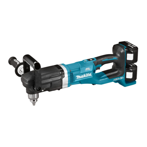
HIOS BL-2000 User manual

BL-2000
BL-3000
BL-5000
BL-5000-15
BL-5000-20
BL-5020
BL-7000
BL-7000HT
BL-7000-20
BL-OPC•BL-ESD•BLQ-CR
BLQ-ESD•BLQ-CR-ESD
Suction•BL-SS
15A
111-6 Akiyama, Matsudo City, Chiba Pref., Japan
TEL: +81 (JAPAN) 47-392-2001
FAX: +81 (JAPAN) 47-392-7773
(anti-static electricity
is standard)
Operation Manual No.: ET-A010
Brushless Driver
BL Series
Operation Manual
(September 2015)
HIOS Inc.
Utilizing 100%post-consumer
recycled paper pulp

- 2 -
Thank you for your purchase of the BL-2000,
BL-3000, BL-5000 or BL-7000 brushless driver.
1. Name of Parts
BL-2000 BL-3000
Joint ring Joint ring
Hanger
Hanger
Switch lever
Rotation direction
switch
Driver cord
Driver cord
Driver cord plug
Driver connector
Rotation
direction switch
Switch
lever
Rotate the protect cover
CCW to take it off and
adjust the torque with
torque adjusting nut.
Torque adjustment
nut protect cover
Joint shaft collar
Torque adjustment nut
Adjusting bolt
(torque adjusting scale)
Bit

- 3 -
2. Accessories
• Bits
• Torque adjusting spring
• There are 2 torque adjusting springs for BL-2000.
In the BL-2000, stronger spring(Black) is installed.
If you want to use weaker spring then replace with
accessory(Yellow) spring.
Select the spring depends on your fastening torque.
• Hex nut L wenches (for BL-5000, BL-7000)
BL-5000 BL-7000
LEVER
PUSH
Joint ring HangerHanger
Torque
adjustment nut
Bit
Bit
Rotation
direction
switch
Rotation
direction
switch
Switch
lever
Switch
lever
Joint shaft collar
Lever/push-to
-start switch
Driver cord plug
Driver cord Driver cord
Driver connector

- 4 -
■ Specications
BL-Series (BL-OPC•BL-ESD•BLQ-CR•BLQ-ESD•BLQ-
CR-ESD•BL-SS)
Lever start type Model BL-2000
BL-2000SS BL-3000
BL-3000SS*
BL-5000
BL-5000SS
BL-5000-15 BL-5000-20
Push-to start type Model
—
Output
torque range
N•m 0.02 - 0.20.2 - 0.55
0.2 - 0.35* 0.2 - 1.2 0.3 - 1.2 0.5 - 1
lbf•in 0.17 - 1.71.7 - 4.8
1.7 - 4.8* 1.7 - 10 2.6 - 10 4.3 - 8.7
(kgf•cm) (0.2 - 2) (2 - 5.5)
(2 - 3.5)* (2 - 12) (3 - 12) (5 - 10)
Torque Switching Stepless Adjustment
Unloaded Rotation
Speed(r.p.m)±10%
HI 990 980 900 1,500 2,200
LOW 650 680 590 1,000 1,500
Screw
size
Machine Screw
1.0 - 2.3 1.7 - 2.3 2.0 - 3.0 2.0 - 3.0 2.0 - 3.0
Tapping screw
1.0 - 2.0 2.0 - 2.3 2.0 - 3.0 2.0 - 2.6 2.0 - 2.6
Weigh (g) 254 320 360 360 360
Bit
type
HIOS Shank H4 H4 H4 H4 H4
HEX Shank —1/4 HEX
H5 & 5 HEX
or 1/4 HEX
H5 & 5 HEX
or 1/4 HEX
H5 & 5 HEX
or 1/4 HEX
Power
Supply
T-45BL ○○○
○ * ○ *
T-70BL ○○○○○
Cord Length (attached cord
table according to the type)
Standard A B B B B
BL-OPC D E E E E
BL-ESD AAAAA
BLQ-CR F H H H H
BLQ-ESD F F F F F
BLQ-CR-ESD F F F F F
BL-SS A B B — —
Lever start type Model BL-5020 BL-7000 BL-7000HT
BL-7000-20
Push-to start type Model
Output
torque range
N•m 0.5 - 2 0.7 - 2.8 0.7 - 3.5 0.5 - 1.5
lbf•in 4.3 - 17.4 6.1 - 24 6.1 - 30 4.3 - 13
(kgf•cm) (5 - 20) (7 - 28) (7 - 35) (5 - 15)
Torque Switching Stepless Adjustment
Unloaded Rotation
Speed (r.p.m)±10%
HI 750 960 700 2,200
LOW 500 630 500 1,500
Screw
size
Machine Screw
2.0 - 4.0 2.6 - 5.0 2.6 - 4.0 2.6 - 4.0
Tapping screw
2.0 - 3.0 2.6 - 4.0 2.6 - 4.0 2.6 - 4.0
Weigh (g) 360 640 640 640
Bit
type
HIOS Shank
H5 & 5 HEX H5 & 5 HEX H5 & 5 HEX H5 & 5 HEX
HEX Shank 1/4 HEX 1/4 HEX 1/4 HEX 1/4 HEX
Power
Supply
T-45BL
○ *
———
T-70BL
○ *
○○○
Cord Length (attached cord
table according to the type)
Standard B C C C
BL-OPC E E E E
BL-ESD AAAA
BLQ-CR H I I I
BLQ-ESD F F F F
BLQ-CR-ESD F F F F
BL-SS ————
(Note) Use only 2(HI) power outlet with the * models.
These models may not perform properly on 1(LOW) power outlet.
● Output torque range and rotational speed in the above specications
is for Model BL-2000, BL-3000 driver, using the T-30BL power pack or
driver Models BL-5000 and BL-7000, using the T-70BL power pack.

- 5 -
●Referenceofattachedcordfordrivers
Type AttachedCord Type AttachedCord
A 2m Cord ESD Type (5P) F 2m Cord ESD Type (5P) & Iinclude
ESD Vinyl tube
B 1.5m Cord Type (5P) G 2m Cord ESD Type (5P) & Iinclude
Vinyl tube
C 2m Cord Type (5P) H 1.5m Cord Type (5P) & Iinclude
Vinyl tube
D 2m Cord ESD Type (6P) I 2m Cord Type (5P) & Iinclude Vinyl
tube
E 2m Cord Type (6P)
* The applicable cord especially for OPC is 6PIN type. (*Regular cord is
5PIN type) Combination type screw driver (ex. ESD+OPC) is attached
applicable type cord (2m).
●ExternalDimensions
172
∅26
207
Max.∅38 Min.∅26
(WD cut shape)
BL-5000
BL-2000
∅32.5
192
BL-3000
239
Max.∅40 Min.∅36
(WD cut shape)
BL-7000
■ PowerSupplies
The Brushless Driver must be operated together with a Power
Pack.
Powering the Brushless Driver with the Hios T-30BL and the
T-70BL Power Pack will insure operation of the driver at its
full capacity.
●BLdriverandPowerPackcombinations
PowerPackModel Max.numberofdrivers
BL-2000 BL-3000 BL-5000 BL-7000
Power Pack for
Brushless Driver
T-45BL 1 1 ○
T-70BL 1 1 1 1
■ CautionstoObserveWhenUsing
1. In push-to-start mode, the driver will begin turning in
response to only a slight pressure. Take care that it is
under complete control when in push-to-start mode.
2. The driver can be damaged by accidental falls or impacts.
3. Take care to avoid exposing the driver to oil based

- 6 -
substances.
4. The driver does not require lubrication and should not be
lubricated.
■ Pre-operatingPreparations
1. Check that the proper Power Pack is being used with the
driver.
2. Connect the Power Pack to plug AC100 to 240 V .
3. Turn the power switch on, check to see that the power
switch light of the Power Pack goes on, then switch the
power off. If the light didn't go on, replace the fuse with the
spare provided with the pack, referring to the Power Pack
specications.
4. If you want to use as "Push start", follow the instructions
"5" below.
5. To operate in Push-to-start Mode.
BL-3000
Use tweezers to switch lever start/
push start.
BL-5000
Rotate 1the hex head screw to
detach 2the switch lever and
set the start switch to the "PUSH"
position.
Use it without attaching the hex
head screw and the switch lever.
BL-7000
Rotate the hex head screw to detach
the switch lever (Fig-1) and reattach
the switch lever upsidedown. (Fig-2)
To convert the starting mechanism from lever-start to push-to-start,
remove the hex head screw and switch lever, turn the switch lever
upside-down and use the hex head screw to re-fasten the switch
lever.
6. Connect the driver power cord to the Power Pack. (Both
ends of this cord have the same type of connector. Be sure
that the interlocking guide ts together properly and tighten
the joint ring.)
Hex head
screw
Switch lever
LEVER
PUSH
Hex head
screw
Switch lever
1
2
Fig-2Fig-1

- 7 -
■ OperatingProcedure
1. Attach a bit to the driver. (See "Attaching a Bit" below)
• If using model BL-3000, remove the torque adjustment nut
cover before attaching a bit.
2. Set the driver to clockwise or counter-clockwise rotation as
desired, then push the switch lever to check that the driver
turns in the correct direction. After checking, be sure the
switch is left on the clockwise setting.
Caution: Always turn the power off before reversing the
rotationdirectionsetting.
3. Make the desired torque adjustment setting. (See "Torque
Adjustment" below.)
4. Begin fastening by tting the end of the bit to the head of a
screw to be tightened and pulling the switch lever.
• In push-to-start mode, the driver automatically goes on
when pressure is applied to the bit end.
5. The clutch will immediately stop rotation when the preset
torque level is reached. At this point, raise the driver from
the screw and release the switch lever. Repeat this cycle
for each tightening operation.
• In push-to-start mode, do not raise the driver from the
screw head until rotation has stopped.
6. Set rotation direction to counterclockwise to loosen a
screw. Very tightly fastened screws can be loosened by
repeatedly applying the driver to the screw to obtain short
bursts of rotation force.
■AttachingaBit
Besuretoeitherturnthepower
switch off or disconnect the power
cordbeforeattemptingtochange
bits.Failuretodosocouldbe
especiallydangerousifthedriveris
set to push-to-start mode. In either
case,unexpectedstartupofthe
drivercouldresultininjury.
If using model BL-3000, BL-5000 or BL-
7000, raise the joint shaft collar at the
bottom of the tool, then insert the bit.
• As for BL-2000, press the Joint-shaft
collar towards inside of the screwdriver
and insert the bit.
• If using model BL-3000, push the joint
shaft collar into the tool to attach the bit.
Then pull on it to be sure it is properly
attached.
Caution
Joint shaft
collar

- 8 -
■ TorqueAdjustment
Torque is controlled by the tension on a spring inside the
torque adjustment nut. If set the nut tighter, the output torque
is higher.
• The adjustment torque scale does not give the actual
output torque. Please regard the output torque graph as
an approximate guide.
■ TorqueAdjustmentProcedure
1. If you have a predetermined torque value, set that value
on the scale using the torque adjustment nut.
• The BL-2000 Electric Screwdriver have ‘Double nut
system’ (Nut xing ring and Torque adjusting nut) to avoid
loosening from shock or vibration to the Screwdriver.
● BL-2000
• At rst, keep the Nut xing ring
to t the scale at which, if you
want to adjust.
• Then turn the Torque adjusting
nut toward the Nut xing ring.
• Lastly, to avoid the loosening of
the ‘Torque adjusting nut fasten
strongly the Nut fixing ring by
holding the ‘Torque adjusting
nut’.
●BL-3000
If using model BL-3000, make
the setting by pushing the nut
collar upwards, removing the
torque adjustment nut
and turning it so the
point over the nut aligns
with the groove.
●BL-5000, BL-7000
If using model BL-5000 or 7000,
set the torque adjustment nut
using the hex wrench that is
provided.
Torque scale
BL-2000
Torque
adjustment nut
Nut securing ring
BL-3000
Torque
adjustment nut
Nut securing
ring
Torque
adjustment
scale
5 mm hex nut L wrench

- 9 -
2. Turn the driver on and tighten a screw to check that the
driver stops at a satisfactory level of tightness.
3. Readjust the torque setting, tighter or looser, as necessary.
Repeat the procedure until you arrive at the desired torque
setting.
It is recommended that a Hios torque meter be used to
measure torque. Use the HP series for measurement of the
driver's torque setting and the HDP series or the HDM series
to measure loosening or tightening torque of screws.
■ IfRepairsareRequested
Check the items listed in the table below, and if a malfunction
is found, contact your store of purchase of our company.
Always include your warranty card when sending in the driver
for repairs.
Symptoms Cause and Treatment
The driver motor
sometimes fails to operate
• Is the cord severed?
Stop any work and request repairs.
The driver is weak and
cannot tighten screws
sufciently
• Is the torque setting at the correct position?
Refer to the output torque guidance

- 10 -
■ ApproximateGuidanceofOutput
Torque(duringHIinput)
Scale ring setting
Scale ring setting Scale ring setting
Scale ring setting Scale ring setting
Black
(installed)
BL-3000
White
BL-3000SS*
White
Yellow
(attached)
N•m
0.25
0.2
0.15
1.5
1.0
0.5
0.1
0.05
0.03
N•m
N•m N•m
0.8
0.5
0.6
0.7
0.4
0.3
0.2
0.1
0.02
12345678
12345678
12345678
BL-5000
BL-5000-SS
BL-5000-15
BL-5000-20
2.0
1.5
1.0
0.5
12345678
BL-5020
3.0
1.0
0.7
0.5
1.5
2.0
2.5
N•m
1 2345678910
Scale ring setting
1 2345678910
BL-7000
BL-7000-20
BL-5000
BL-5000-SS
BL-5000-15
BL-5000-20
BL-7000
BL-7000-20
3.5
3.0
2.5
2.0
1.5
1.0
0.5
0.7
N•m
BL-7000HT
BL-2000
BL-2000SS
BL-3000
BL-3000SS*

- 11 -

- 12 -
This manual suits for next models
3
Table of contents
Other HIOS Power Screwdriver manuals
HIOS
HIOS BLF-2000 User manual
HIOS
HIOS CL-9000NL User manual
HIOS
HIOS BLG-BC1 Series User manual
HIOS
HIOS VZH-1820 User manual
HIOS
HIOS JUKUREN BLG-BC2 series User manual
HIOS
HIOS JUKUREN BLG-BC2 series User manual
HIOS
HIOS DCD-40L User manual
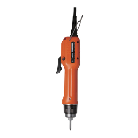
HIOS
HIOS BLG Series User manual

HIOS
HIOS CL-9000 User manual
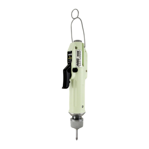
HIOS
HIOS CL-2000 Installation manual
Popular Power Screwdriver manuals by other brands
Würth
Würth ASS 14-1/4" Translation of the original operating instructions
EINHELL
EINHELL TE-CD 18/2 Li Original operating instructions
DeWalt
DeWalt DCF620 Original instructions
Lux Tools
Lux Tools A-BS-20-D instruction manual
Erbauer
Erbauer ECDT18-Li-2 Original instructions
Conrad
Conrad 2524385 operating instructions
