HIOS JUKUREN BLG-BC2 series User manual

Brushless Screwdriver®
with built-in Screw Counter and Pulse System
“JUKUREN” BLG-BC2 series
Operation Manual
(August 2018)
<Note>
BLG-BC2 I/O Cable set is optional (P/N: BLG-BC2-3010).
Contents
・BLG-BC2 I/O Cable
・Application software (Including the instruction manual)
・Communication specifications
HIOS Inc.
1-16-5 Akiyama, Matsudo City, Chiba Pref., Japan 270-2223
TEL: +81-47-392-2001FAX: +81-47-392-7778
NO.ET-A011-BC2 18A
- 1 -
Thank you for your purchasing HIOS “JUKUREN” BLG-BC2 Screwdriver.
■Pulse System
The pulse system is a mechanism using an electric signal (pulse) that occurs during motor revolutions.
By installing several fasteners into the assembly the driver learns the numbers of motor revolutions
required to correctly tighten the fasteners to the desired torque. The driver then establishes the minimum to
maximum revolutions for process acceptance and displays the result of screw tightening with the LED green
and red lights on the unit.
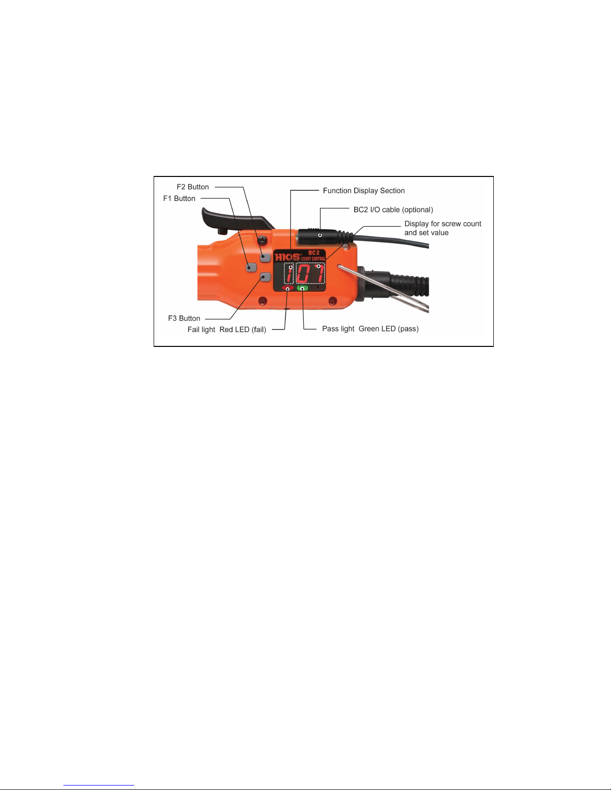
■Button and display descriptions
1. Screw Count Display Section/Set Value Display Section
●The screw fastening count set value is displayed when the counter function is On. After starting the count,
the remaining screw fastening count is displayed.
●The count decreases with each screw fastening operation and the remaining screw fastening count is
displayed.
2. Function display section
●The symbol corresponding to the function is displayed in the setup mode. (See page 3.)
3. F1 Button
●Press and hold the F1 button until the “P” then the “On” is displayed
●Continue to press the F1 button to scroll through the setup functions
●Press and hold the F1 button until the buzzer sounds twice to save the change.
4. F2 and F3 Buttons
●Using these buttons, the set value can be changed in the setup functions.
Some set values are limited depending on the function that is being set.
●Press and hold the F2 button until「r0」is displayed and the Pass/Fail lights blink.
5. Pass Light*
●When the screw fastening is done properly, the green LED light turns on.
6. Fail Light*
●When the screw fastening is done improperly, the red LED light turns on.
* The Pass or Fail light turns off, when the lever switch is turned on.

- 2 -
■Direct Teaching
(Note)
Before Direct Teaching, fasten 1 or 2 screws to adjust the start position. (must-do)
1.
F2
Button →Press and hold until “r 0” is displayed and Fail/Pass lights blink.
2. Start Direct Teaching.
Fasten 3 or more of the same screws into the same joint.
Direct teaching needs to be done using screws, parts and a method of pick up which will be used
in your production.
3. F3 Button
→Press to select the acceptable range of Pass/Fail criteria.
It is displayed in the order of ±0%, ±5%, ±10%,±15%, ±20%.
4. F1 Button → Press to confirm the reference values of Pass/Fail including the acceptable range.
Example >
Assuming the reference values including the acceptable range are from 90 to 120,
the Pass range is from 91 to 119.
(Note)
In order to complete Direct Teaching, make sure to work through all the steps (1-4) .
5. F2 Button → Press and hold until the buzzer sounds twice to complete Direct Teaching.
6. All set!
■
List of setup functions
Fail Pass
Control Unit
Display:
No. of motor revolutions is displayed and either Pass/Fail light gets on.
・The No. of motor revolutions is displayed up to triple digits.
・The No. of revolutions can be displayed up to 999.
F1 Button, F2 Button, F3 Button:
These are used for each setup.
3rd, 2nd, 1st digit

- 3 -
Dis-
play
Mode (default)
Symbol
Description
(1)
Counter
On: When selected, the counter function is available.
OFF:
When selected, it is used as a normal driver.
On/OFF
(2)
Count
The screw fastening count value is set.
・
Setting range: 1 to 99
(3)
Min. revolutions*
The minimum numbers of motor revolutions .
・
Display range: 000
-
999,
・
Setting range : 000
-
999
* Hundreds place is not displayed.
Fx. Min. no. is “110” but only “10” is displayed on the screen.
Max. revolutions*
The maximum numbers of motor revolutions
・
Display range: 000
-
999,
・
Setting range : 000
-
999
* Hundreds place is not displayed.
Fx. Max. no. is “120” but only “20” is displayed on the screen.
Refer to “3. Value Setting for Each setup functions” on page 4 for details.
If the detected pulse is smaller than the minimum or larger than the maximum,
the red LED light (Fail) turns on.
If the detected pulse is larger than the minimum and smaller than the maximum,
the green LED light (Pass) turns on.
(4)
Work Reset Timer
The buzzer sound time period after the work is completed is set.
・Setting range: 0.0-3.9 seconds
Note: Set it based on the Reverse Count Timer set value.
(5)
Reverse Count Timer
The time period until the Reverse Count is performed is set.
Set the Work Reset Timer operation time based on the time period up to
when the Reverse Count is performed.
・
Setting range: 0.1
-
1.0 second
(Note) It is available when the “Reverse Count Enable” has been set in the
System setting.
(6)
System Setting
Each buzzers and Reverse Count Enable/Disable is set up.
The Setting is performed with a combination of the tenth digit and single unit
digit.
●2nd digit
0: Buzzers Enable / Reverse Count Enable
1: Buzzers Enable / Reverse Count Disable
2: Buzzers Disable / Reverse Count Enable
3: Buzzers Disable / Reverse Count Disable
●1st Digit
2: Driver shut off (Torque Up) buzzer Disable
3: Driver shut off (Torque Up) buzzer Enable
(7)
Over Time
This sets whether or not the Over Time/Short Time error is detected.
Short Time
0: Neither of motor revolutions is detected.
1: Only the minimum no. is detected.
2: Only the maximum no. is detected.
3: Both are detected.
(8)
Total no. of
The total No. of the driver shut off is displayed.
the driver shut off
This counts all the driver shut off regardless of whether the Count is On/OFF.
How to read the values:
2nd digit:×1 million cycles
1st digit:
×
100,000 cycles
- 4 -
(9)
No Error Time
for double fastening
No error time can be set with three bars + values in order to avoid unnecessary
errors during double fastening.
・
This setting is enable only when fastening is done properly.
・Display range: 0.0-9.9 ・Setting range: 0.0-9.9 sec
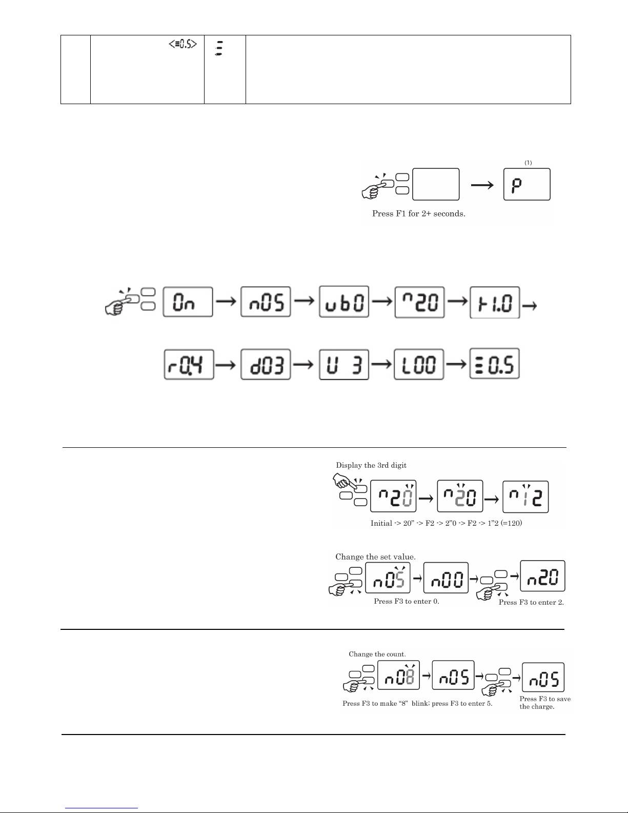
■Screw Counter
1. Changing to the Setup Mode:
Press and hold the F1 Button until “P” then the
“On” is displayed.
2. Setting Mode:
Pressing the F1 button allows you to scroll through each setup functions.
Refer to “List of setup functions” on page 3 for the changing and setting any functions.
Note: The no. of motor revolutions is displayed up to triple digits.
3. Value Setting for Each setup functions:
●Verify the hundreds (3rd) digit.
Press the F2 Button to change the figure position
for setting.
●Change the value.
Pressing the F3 button increases the value one by one.
Press and hold the F1 button until the buzzer sounds
twice to save the change.
4. Change cycle count.
Press F1 Button for more than 2 sec. to increment to
display number. Follow the procedure described in
3 above.
The count can be set between 1 and 99.
(Count )
(
Pulse/ Min
)(
Pulse/ Max
)
(Work Reset Timer)
(Reverse Count Timer)
(System)
(Over Time/
(Total No. of the
(No Error Time for
Short Time) driver shut off) double fastening)
(1) (2) (3)
※
(3)
※(
4
)
(5) (6) (7)
(8)
(
9
)
(Count)
(Min. revolutions)
(Max. revolutions)
(Work Reset Timer)
- 5 -
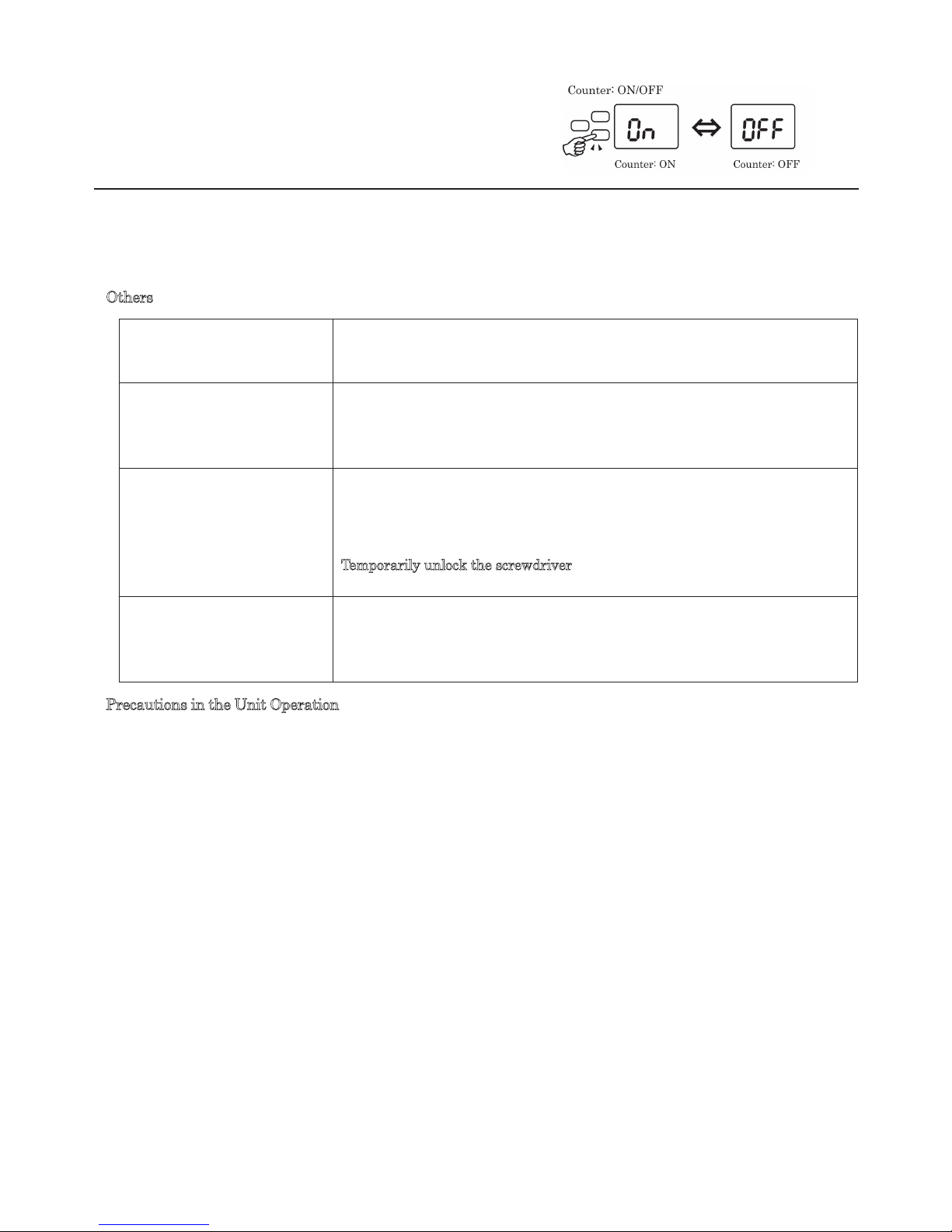
5. Turn the count ON/OFF
Press F1 Button for more than 2 sec. to turn the counter
ON/OFF
(Note) The way of setting the functions is common except how to set the counter ON/OFF.
■Others
■Precautions in the Unit Operation
●When this unit is used in combination with the existing HIOS external counter, the driver counter does not
synchronized with the external counter. So, use them based on the external counter function.
Otherwise, turn off the driver’s counting function before use.
・Combination Available with External Counter Models Power Unit
BLOP-STC3 with the Screw Counter
Separate Counter BLOP-SC1
●Appropriate operation environment.
・Do not use the unit in an environment where the ambient temperature is outside the range of +5 to 40 ºC.
・In an area with static electricity, use this unit only after removing the static electricity.
The count is to be returned to
the default value during the
screw fastening operation.
Pressing the F3 button for 2 seconds or more, resets the screw fastening count
value.
If you fasten a screw after the
driver turns counterclockwise:
There may be some difference in results of motor revolutions after the driver
turns counterclockwise as the start position may have changed.
In this case, the start position needs to be reset by fastening a screw before
starting actual fastening again in order to avoid errors.
"
---
" is shown on the
display.
Once the cumulative usage count exceeds 1 million, "
---
" blinks on the
display and the screwdriver is locked.
In such case, overhaul or maintenance is required. Please contact your dealer
or HIOS.
Temporarily unlock the screwdriver
Press and hold F2 and F3 buttons at the same time.
To see the version of
screwdriver.
Press and hold F1 button
→
Press F3 button (deactivate screw-counter)
→
Press and hold F1.
The current version will be displayed following the "HIOS" text.
Activate screw-counter if necessary.
Other manuals for JUKUREN BLG-BC2 series
1
Table of contents
Other HIOS Power Screwdriver manuals

HIOS
HIOS CL-9000NL User manual

HIOS
HIOS BL-2000 User manual

HIOS
HIOS BLG Series User manual

HIOS
HIOS BLG-BC1 Series User manual

HIOS
HIOS CL-2000 Installation manual

HIOS
HIOS BLF-2000 User manual

HIOS
HIOS VZH-1820 User manual

HIOS
HIOS BLG-7000BC2-GT-S User manual

HIOS
HIOS CL-9000 User manual

HIOS
HIOS DCD-40L User manual


