Hirschmann Mentor EI65 Use and care manual

HIRSCHMANN
LENGTH-ANGLE-RADIUS-LOAD
INDICATING SYSTEM
Mentor EI65
Software Version 1.0
CALIBRATION MANUAL
P/N 190232 REVISION - 03/06/09


Calibration Manual Hirschmann Mentor EI 65
Mentor EI 65 CALIBRATION MANUAL 190232 REVISION - 03/06/09
NOTICE
The information in this document is subject
to change without notice.
Hirschmann makes no warranty of any kind with regard
to this material, including, but not limited
to the implied warranties of merchantability
and fitness for a particular purpose.
Hirschmann shall not be liable for errors contained herein
or for incidental or consequential damages in
connection with the furnishing, performance
or use of this manual.
This document contains proprietary information
which is protected by copyright. All rights are
reserved. No part of this document may be
photocopied, reproduced, or translated to
another language without prior consent of Hirschmann.


Calibration Manual Hirschmann Mentor EI 65
Mentor EI 65 CALIBRATION MANUAL 190232 REVISION - 03/06/09
Table of Contents
1 GENERAL INFORMATION ..............................................................................................1
2 WARNINGS .....................................................................................................................1
3 ESSENTIAL INFORMATION FOR CALIBRATION: .........................................................2
4 CALIBRATION .................................................................................................................5
5 OPERATIONAL CHECKS..............................................................................................14
APPENDIX A - MECHANICAL ADJUSTMENT OF SENSORS............................................15


General Information
Mentor EI 65 CALIBRATION MANUAL – VERSION 1.0 190232 REVISION - 03/06/09
1
1 GENERAL INFORMATION
The Length-Angle-Radius-Load Indicating System Mentor EI 65 must be calibrated after
completing installation, crane modification, or anytime there is an indication of inaccuracy.
The calibration will match the sensor installed on the industrial crane. Refer to the
Installation Manual for the system and sensor installation.
Prior to starting the calibration, it is advised to first read over this procedure in its entirety.
This will also allow you a chance to obtain any necessary information. The purpose of this
manual is to provide calibration information required before operating the system. Refer to
the Operator Manual for system description and console controls.
REFERENCE INFORMATION:
Hirschmann Length-Angle-Radius-Load Indicator System Mentor EI 65 Operator’s Manual.
Hirschmann Length-Angle-Radius-Load Indicator System EI 65 Installation Manual.
2 WARNINGS
Always refer to operational instructions and load charts provided by the crane manufacturer
for specific crane operation and load limits.
The Length-Angle-Radius-Load Indicating System Mentor EI 65 is not and shall not be, a
substitute for good operator judgment, experience, or use of acceptable safe operating
procedures.
The operator is responsible for operating the crane within the manufacturer's specified
parameters.
The crane operator shall ensure that all warnings and instructions provided by the
manufacturer are fully understood, observed, and remain with the crane.
Prior to operating the crane, the operator must carefully read and understand the
information in the Operator's Manual so that he knows the operation and limitations of the
Length-Angle-Radius-Load Indicating System Mentor EI 65.

Calibration Manual Mentor EI 65
Mentor EI 65 CALIBRATION MANUAL – VERSION 1.0 190232 REVISION - 03/06/09
2
3 ESSENTIAL INFORMATION FOR CALIBRATION:
3.1 Prior to powering up the system, verify all wiring. It is not necessary to wire the
unused analog input channels.
3.2 Mechanically set the length and angle sensors as follows: (See Appendix A.
Mechanical Adjustment for Sensors).
xLength Sensor - With the boom sections fully retracted set the length potentiometer
by turning the center screw counter clockwise slowly to a soft stop.
xAngleSensors:Aligntheanglesensors with the boom at zero degrees.
3.3 Write down the following geometric measurements, which will be used during
calibration. (See Figure 1. Crane Measurements). The measurements taken should be
in units that correspond to the load chart. (i.e. lbs/feet, Kg/meters, US-Tons/feet,
Metric-ton/meters).
ESSENTIAL INFORMATION FOR CALIBRATION:
Mentor EI 65 CALIBRATION MANUAL – VERSION 1.0 190232 REVISION - 03/06/09
3
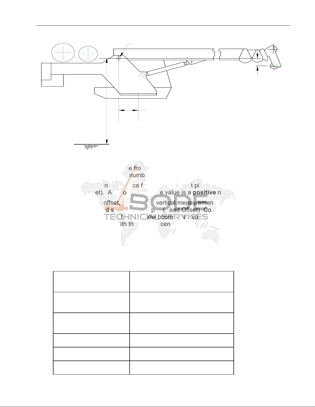
FIGURE 1. CRANE MEASUREMENTS
DIM B
DIM A
GROUND
DIM C
CENTER LINE
OF ROTATION
BOOM FOOT PIVOT PIN
Dimension A: The vertical distance from the boom foot pivot pin to the ground. (Elevation
Offset). This is always a positive number.
Dimension B: The horizontal distance from the boom foot pivot pin to the centerline of
rotation. (Radius Offset). As shown above the value is a positive number.
Dimension C: The head offset, which is the vertical measurement between the boom foot
pivot pin to the lower head sheave center pin. (Head Offset) Configurations as shown
above (lower head sheave center pin below boom foot pivot pin) have the value entered as
a negative number. Booms with the sheave center pin above the boom foot pivot pin are
entered as a positive number.
Jib extension lengths minimum and maximum.
Write the dimensions in the Table provided.
Table 1. Measurements
Dimension A (Elevation
Offset)
Dimension B (Radius
Offset)
Dimension C (Head
Offset)
Jib 1 min/max
Jib 2 min/max
Jib 2 angle min/max

Calibration Manual Mentor EI 65
Mentor EI 65 CALIBRATION MANUAL – VERSION 1.0 190232 REVISION - 03/06/09
4
3.4 Calibration of a linerider will require the hoist rope line pull information, which should
be provided by the manufacturer. Use single part line when calibrating the linerider.
Lineriders require specific wire rope size. See Table 2 to ensure your rope size
matches your linerider that is provided.
NOTE: A new wire rope is normally oversized, and the oversized amount will depend on the
diameter of the rope. With normal wear, the inner core breaks down and the diameter
decreases. See manufacturer’s guidelines for wire rope replacement conditions.
Table 2. Lineriders should match the wire diameter of your hoist rope.
ITEM NUMBER
DESCRIPTION with WIRE ROPE SIZE
WIRE ROPE
DIAMETER
ADVISED RANGE
048-311-060-001 SENSOR, LINERIDER SKM311 1/4" r1/32
048-311-060-002 SENSOR, LINERIDER SKM311 1/2" r1/32
048-311-060-003 SENSOR, LINERIDER SKM311 9/16" r1/32
048-312-060-002 SENSOR, LINERIDER SKM312 3/4" r1/32
048-312-060-001 SENSOR, LINERIDER SKM312 5/8" r1/32
048-312-060-003 SENSOR, LINERIDER SKM312 7/8" r3/64
048-312-060-004 SENSOR, LINERIDER SKM312 1" r3/64
048-312-060-005 SENSOR, LINERIDER SKM312 1 1/8 r3/64
031-300-060-009 SENSOR, LINERIDER SKM312 1-1/4 r1/16
3.5 Calibration of dead end force transducers requires two parts of line.
3.6 Always follow the manufacturer’s guidelines when operating the crane.
3.7 Always work within the capacity of the rated load charts provided by the manufacturer.
3.8 The total load includes the load, rigging, cables, and hook block.
3.9 Test load should be 75% of maximum rated load for the crane’s configuration or
condition.
NOTE: To comply with SAE J376 standards, the test load must be to a known accuracy of
r1%.

Calibration
Mentor EI 65 CALIBRATION MANUAL – VERSION 1.0 190232 REVISION - 03/06/09
5
4 CALIBRATION
4.1. Power up the system, the screen will display Mentor EI 65 and the software revision.
4.2. Within 5 seconds, press the “i” button in order to start calibration. The screen will
change to “CALIB. PASSWORD”. If this button is not pressed the screen then changes
to the existing operating configuration. See Operators Manual for operating instructions.
4.3. Enter the calibration password “0815”. Use the “UP” and “DOWN” buttons to select the
number and the “OK” button to confirm each entry.
Enter 0 - OK
8 - OK
1 - OK
5 - OK
NOTE: From this point forward, the sections can be made by pressing “OK” or skipped by
pressing arrow “DOWN”.
4.4. Select CONFIG DEFAULT by pressing the “OK” button.
4.5. CONFIG LANGUAGE - Press “OK” to select and use the arrow “UP and DOWN”
buttons to select a language; English, Spanish, or French. When complete press the
“OK” button.
4.6. CONFIG UNITS - Press “OK” to select and use the arrow “UP and DOWN” buttons to
select the load units; LBS (lbs), TONS (t), KILOGRAMS (kg), US-TONS (tons). When
complete, press the “OK” button.
NOTE: Select the units used in the load charts provided by the manufacturer.
4.7. SET CRANE DIMENSIONS - Calibrates the angle sensor and defines the required
geometric measurement of the crane. Press “OK” to select.
4.7.1. SET BOOM ANGLE - Measure the boom angle, using an inclinometer or similar
device. Press the arrows “UP or “DOWN” to adjust the displayed angle to match
the measured angle. Press “OK” to enter angle.
NOTE: Measurements should be in units that correspond to the load chart. (i.e. lbs/feet,
Kg/meters, US-Tons/feet, Metric-ton/meters).
4.7.2. ELEV. OFFSET – Elevation Offset is the vertical measurement from the boom
foot pivot pin to the ground, as taken in step 3.3.A. Press the arrows “UP and
DOWN” to adjust the display. Press “OK” to enter measurement.

Calibration Manual Mentor EI 65
Mentor EI 65 CALIBRATION MANUAL – VERSION 1.0 190232 REVISION - 03/06/09
6
4.7.3. RADIUS OFFSET - This is the horizontal measurement between the boom foot
pivot pin and the centerline of rotation, as taken in Step 3.3.B. If the boom foot
pivot pin is located behind the centerline of rotation, the value needs to be
entered as a positive. If the Pivot pin is forward of the centerline of Rotation the
value needs to be entered as a negative. Press the arrows “UP or “DOWN” to
adjust the display. Press “OK” to enter measurement.
4.7.4. HEAD OFFSET - The vertical measurement between the boom foot pivot pin
and the lower head sheave center pin, as taken in Step 3.3.C. If the center pin
is below the boom foot pivot pin, enter the value as a negative by using the
arrows “UP or DOWN” to adjust the display. Press “OK” to enter measurement.
4.8. SET BOOM TYPE - This section configures the type of main boom, FIXED or TELE.
Press the “OK” button and proceed by answering the questions on the screen.
4.8.1. MAIN BOOM FIXED? - Press “OK” to accept or the arrow “DOWN” for next
selection.
4.8.1.1. Enter the minimum length using the arrows “UP or DOWN” to adjust
the display. Press “OK” to enter length.
4.8.1.2. Enter the maximum length using the arrows “UP or DOWN” to adjust
the display. Press “OK” to enter length.
4.8.2. MAIN BOOM TELE? - Press “OK” to accept or the arrow “DOWN” for next
selection.
WARNING: The operator is responsible for operating the crane within the manufacturer's
specified parameters.
4.8.2.1. MAIN BOOM MIN? - DRIVE MAIN BOOM ON MIN POSITION! - Fully
retract the main boom. Ensure that the length potentiometer has been
reset by turning the center screw counter clockwise until you have
reached a soft stop. Refer to Section 3.2.
4.8.2.2. Press “OK” to display minimum length preset value.
4.8.2.3. Press the arrows “UP or “DOWN” to adjust the displayed length to
minimum or fully retracted length.
4.8.2.4. Press “OK” to enter length minimum preset value.
4.8.2.5. MAIN BOOM MAX? - DRIVE MAIN BOOM ON MAX POSITION! Fully
extend the main boom; include the power pin fly extension when
applicable.
4.8.2.6. Press “OK” to display maximum preset value.
4.8.2.7. Press the arrows “UP or “DOWN” to adjust the displayed length to
maximum or fully extended length.
4.8.2.8. Press “OK” to enter length.
Calibration
Mentor EI 65 CALIBRATION MANUAL – VERSION 1.0 190232 REVISION - 03/06/09
7
4.9. CONFIG EXTENSION - This section configures two extensions with minimum and
maximum length, a minimum and maximum angle (OFFSET MIN/MAX) for the second
extension (LENGTH 2), and whip extension or variable angled extension with angle
sensor. Use Figures 2 through 5 to help identify your configuration. Press “OK” and
proceed by entering extension lengths, angle, and calibrating whip extension angle.
Configure the extensions that your crane will use and enter zero for unused portions of
CONFIG EXTENSION. Recommendation: Set up the extension’s minimum length as
zero, so if this extension is removed you can change the length in the SELECT section
of operation instead of entering calibration mode to remove extension.
JIB LGTH_1 is a section with a fixed length, primarily used with whip sections. If a
non-zero value is entered for its length, the operator will have the choice of using or not
using this section, but will not be able to select its length. There is no angle offset
available for this section. This length is added to the measured boom length for
calculating radius and tip height.
JIB LGTH-2 is either a fixed extension or a whip extension. The operator will be able
to adjust the length and angle (fixed only) within the limits set.
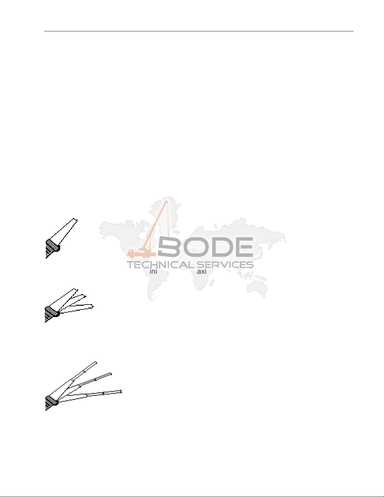
Figure 2. Fixed Extension
(Enter extension as Length 2 minimum and maximum, with angle min and max as zero)
Figure 3. Fixed, Offsettable Extension
(Enter extension as Length 2 minimum and maximum and angle offset minimum and
maximum)
Figure 4. Tele-Offsettable Extension
(Enter extension as Length 2 minimum and maximum and angle offset minimum and
maximum)

Calibration Manual Mentor EI 65
Mentor EI 65 CALIBRATION MANUAL – VERSION 1.0 190232 REVISION - 03/06/09
8
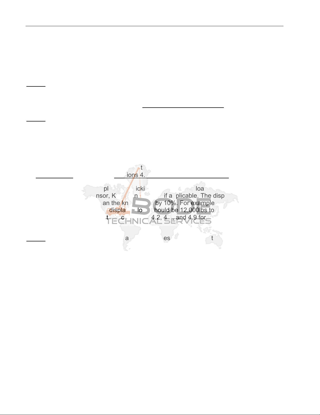
Figure 5. Fixed Extension with Offsetable Jib
(Enter base extension as Length 1. Enter luffing extension as Length 2 minimum and
maximum and set whip extension angle sensor.)
4.9.1. JIB LGTH_1 - Press the arrows “UP or “DOWN” to display the length. Press “OK”
to enter length.
4.9.2. LENGTH_2 MIN - Press the arrows “UP or “DOWN” to display minimum length.
Press “OK” to enter length.
4.9.3. LENGTH_2 MAX - Press the arrows “UP or “DOWN” to display maximum length.
Press “OK” to enter length.
4.9.4. OFFSET MIN - Press the arrows “UP or “DOWN” to display minimum offset
angle. Press “OK” to enter angle.
4.9.5. OFFSET MAX - Press the arrows “UP or “DOWN” to display maximum offset
angle. Press “OK” to enter length.
4.9.6. WHIP EXTENSION - This is a variable angled extension (luffing) with angle
sensor. Press the arrows “UP or “DOWN” to select yes or no and Press “OK” to
confirm entry. If no go to Step 9.
4.9.6.1. WG_OFFSET EXT. - Align the offsetable jib with the extension and/or
main boom so that the angles are equal. Measure the extension angle
using an inclinometer or similar device. Press the arrows “UP or
“DOWN” to adjust the displayed angle to match the measured angle.
Press “OK” to enter angle.
Len
g
th 1
Len
g
th 2

Calibration
Mentor EI 65 CALIBRATION MANUAL – VERSION 1.0 190232 REVISION - 03/06/09
9
NOTE WHEN SETTING THE FORCE – There are 2 possible sets of minimum and
maximum load data when calibrating the force sensors.
x The first set of load data is used to calibrate the force sensor at single or minimum parts
of line and must be completed.
xThesecondsetofdataisusetocalibratethe force sensor with many or maximum parts
of line. The second set of data is not required. If data is not entered, the system will use
a friction factor that is defined in the software.
4.10. SET FORCE 1 FIRST SET - This is the first set of data for the main boom force
sensor.
4.10.1. Press “OK” to calibrate the KMD1 - Main linerider/load cell or press the
arrow “DOWN” button to continue.
4.10.2. PARTS OF LINE - Use the arrows “UP or DOWN” to select parts of line.
NOTE: For the 1st set of data the parts of line should be a small figure.
Recommended is ‘1’. Two parts of line are needed for a load cell and one
part of line for a Linerider.
4.10.3. FORCE 1 ZERO – With no load on the hook block, use the arrows “UP or
DOWN” to enter the value for the minimum force on the main boom.
NOTE: The total load includes the rigging, cables, and hook block.
4.10.4. Press “OK” to confirm Load.
4.10.5. FORCE 1 LOAD - Lift a test load of at least 75% of permissible line pull for
the crane configuration. See crane manufacturer’s data for approximate
load. NOTE: To comply with SAE J376 standards, the test load must be to
a known accuracy of r1%.
4.10.6. Use the arrows “UP or DOWN” to adjust the display load to indicate your
total test load. NOTE: The total load includes the load, rigging, cables, and
hook block.
4.10.7. Press “OK” to confirm total load.
4.11. SET FORCE 1 2nd SET - This is the second set of data for the main boom force
sensor. NOTE: The first set of data must be used before entering the second set of
data. NOTE: For the second set of data, the parts of line should be increased. The
maximum number of possible parts of line is recommended.
4.11.1. Press “OK” to calibrate the KMD1 - Main linerider/load cell or press the
arrow “DOWN” button to continue.
4.12. PARTS OF LINE - Use the arrows “UP or DOWN” to select parts of line. NOTE:
For the second set of data the parts of line should be a large figure. The maximum
number of possible parts of line is recommended.

Calibration Manual Mentor EI 65
Mentor EI 65 CALIBRATION MANUAL – VERSION 1.0 190232 REVISION - 03/06/09
10
4.12.1. FORCE 1 ZERO – With no load on the hook block, use the arrows “UP or
DOWN” to enter the value for the minimum force on the main boom.
NOTE: The total load includes the rigging, cables, and hook block.
4.12.2. Press “OK” to confirm Load.
4.12.3. FORCE 1 LOAD - Lift a test load that is different than the first set of data.
See crane manufactures data for approximate load. NOTE: To comply with
SAE J376 standards, the test load must be to a known accuracy of r1%.
4.12.4. Use the arrows “UP or DOWN” to adjust the display load to indicate your
total test load. NOTE: The total load includes the load, rigging, cables, and
hook block.
4.12.5. Press “OK” to confirm total load.
4.13. SET FORCE 2 FIRST SET - This is the first set of data for the auxiliary force
sensor KMD2.
4.13.1. Press “OK” to calibrate the KMD2 – auxiliary linerider/load cell or press the
arrow “DOWN” button to continue.
4.13.2. PARTS OF LINE - Use the arrows “UP or DOWN” to select parts of line.
NOTE: For the 1st set of data the parts of line should be a small figure.
Recommended is ‘1’. Two parts of line are needed for a load cell and one
part of line for a linerider.
4.13.3. FORCE 2 ZERO – With no load on the hook block, use the arrows “UP or
DOWN” to enter the value for the minimum force on the main boom.
NOTE: The total load includes the rigging, cables, and hook block.
4.13.4. Press “OK” to confirm Load.
4.13.5. FORCE 2 LOAD - Lift a test load of at least 75% of permissible line pull for
the crane’s configuration. See crane manufacturer’s data for approximate
load. NOTE: To comply with SAE J376 standards, the test load must be to
a known accuracy of r1%.
4.13.6. Use the arrows “UP or DOWN” to adjust the display load to indicate your
total test load. NOTE: The total load includes the load, rigging, cables, and
hook block.
4.13.7. Press “OK” to confirm total load.
4.14. SET FORCE 2 SECOND SET - This is the second set of data for the auxiliary force
sensor. NOTE: The first set of data must be used before entering the second set of
data. NOTE: For the second set of data the parts of line should be increased. The
maximum number of possible parts of line is recommended.

Calibration
Mentor EI 65 CALIBRATION MANUAL – VERSION 1.0 190232 REVISION - 03/06/09
11
4.15. Press “OK” to calibrate the KMD2 - Auxiliary linerider/load cell or press the arrow
“DOWN” button to continue.
4.15.1. PARTS OF LINE - Use the arrows “UP or DOWN” to select parts of line.
NOTE: For the second set of data the parts of line should be a large figure.
Recommended is the maximum number of possible parts of line.
4.15.2. FORCE 2 ZERO – With no load on the hook block, use the arrows “UP or
DOWN” to enter the value for the minimum force on the main boom.
NOTE: The total load includes the rigging, cables, and hook block.
4.15.3. Press “OK” to confirm Load.
4.15.4. FORCE 2 LOAD - Lift a test load different from the first set of data. See
crane manufactures data for approximate load. NOTE: To comply with SAE
J376 standards, the test load must be to a known accuracy of r1%.
4.15.5. Use the arrows “UP or DOWN” to adjust the display load to indicate your
total test load. NOTE: The total load includes the load, rigging, cables, and
hook block.
4.15.6. Press “OK” to confirm total load.
4.16. CONFIG DISPLAY - This section configures the data that will be displayed on the
screen.
4.16.1. SHOW LOAD? - YES arrow “UP”, NO arrow “DOWN”. Press “OK” to confirm.
4.16.2. SHOW TIP HEIGHT? - YES arrow “UP”, NO arrow “DOWN”. Press “OK” to
confirm.
4.16.3. SHOW HOIST? - YES arrow “UP”, NO arrow “DOWN”. Press “OK” to confirm.
4.16.4. SHOW LENGTH? - YES ARROW “UP”, NO arrow” DOWN”. Press “OK” to
confirm.
4.16.5. SHOW ANGLE? - YES arrow “UP”, NO arrow “DOWN”. Press “OK” to confirm.
4.16.6. SHOW RADIUS? - YES arrow “UP”, NO arrow “DOWN”. Press “OK” to confirm.
4.16.7. SHOW JIB ANGLE? - YES arrow “UP”, NO arrow “DOWN”. Press “OK” to
confirm.
4.16.8. SHOW REEVING? - YES arrow “UP”, NO arrow “DOWN”. Press “OK” to
confirm.
4.17. ANALOG VALUES – This selection displays the sensor output voltages in millivolts.
Can be used to help troubleshoot sensors.

Calibration Manual Mentor EI 65
Mentor EI 65 CALIBRATION MANUAL – VERSION 1.0 190232 REVISION - 03/06/09
12
4.18. CALIBRATE RADIUS – This selection allows the main boom radius to be adjusted for
deflection of the boom. When operating the crane in this section, special care must be
taken to operate in a safe condition, since the Mentor EI65 safety checks and limits are
not active at this time.
4.18.1. BOOM TO MAX LENGTH - This message prompts the operator to extend the
boom to the maximum length possible. If the boom has a power pin section,
this should be extended as well. Press OK or the DOWN arrow when finished.
4.18.2. BOOM TO 60 DEGREES - This message prompts the operator to raise/lower
the boom to the 60 degree position. To make this easier, the angle is displayed.
Press OK or the DOWN arrow when finished.
4.18.3. LOWER ALL LOADS - To calibrate the boom empty deflection, the hook should
be unloaded. Press OK or the DOWN arrow when finished.
4.18.4. CAL EMPTY RADIUS - The empty radius adjustment factor displayed on the
top line may be adjusted using the UP and DOWN arrows. Adjust this until the
radius displayed in the lower left corner of the matches the actual radius
measured with a measuring tape or similar device. Press OK when finished. If
you wish to quickly set the adjustment value to zero, press and hold the TARE
button.
4.18.5. LIFT HEAVY LOAD - This prompts the operator to lift a heavy load until it is no
longer in contact with the ground. For best results a load near the limit at 60
degrees long boom should be used. Care must be taken when lifting the load
since the Mentor EI65 safety checks are not active at this time.
4.18.6. CAL LOADED RAD. - The loaded radius adjustment factor displayed on the top
line may be adjusted using the UP and DOWN arrows. Adjust this until the
radius displayed in the lower left corner of the matches the actual radius
measured with a measuring tape or similar device. Press OK when finished to
exit the radius calibration screens. If you wish to quickly set the adjustment
value to zero, press and hold the TARE button.
NOTE: The radius adjustment factor displayed is only to make data entry easier for
the operator. The actual radius adjustment stored in the software is calculated from
the load, boom angle, actual radius, and displayed radius adjustment factor.
Therefore, the displayed adjustment factor shown when entering the radius adjustment
screen depends on all of these factors.
4.19. CALIBRATE JIB RADIUS – This selection allows the jib radius to be adjusted for
deflection of the jib. When operating the crane in this section, special care must be
taken to operate in a safe condition, since the Mentor EI65 safety checks and limits are
not active at this time. This adjustment is done in addition to the main boom
adjustment. To obtain accurate results, the main boom radius must be calibrated
before adjusting the jib radius. The correct operating mode and hoist must be selected
using the operating mode button before calibrating the jib radius. The main boom

Calibration
Mentor EI 65 CALIBRATION MANUAL – VERSION 1.0 190232 REVISION - 03/06/09
13
calibration MUST be performed first, since this adjustment adds to the adjustment of
the main boom.
4.19.1. LOWER ALL LOADS - To calibrate the jib empty deflection, the hook should be
unloaded. Press OK or the DOWN arrow when finished.
4.19.2. JIB TO 60 DEGREES - This message prompts the operator to raise/lower the
boom or jib until the jib angle is near the 60 degree position. To make this
easier, the angle is displayed. Press OK or the DOWN arrow when finished.
4.19.3. CAL EMPTY RADIUS - The empty radius adjustment factor displayed on the
top line may be adjusted using the UP and DOWN arrows. Adjust this until the
radius displayed in the lower left corner of the matches the actual radius
measured with a measuring tape or similar device. Press OK when finished. If
you wish to quickly set the adjustment value to zero, press and hold the TARE
button.
4.19.4. LIFT HEAVY LOAD - This prompts the operator to lift a heavy load until it is no
longer in contact with the ground. For best results a load near the limit at 60
degrees long boom should be used. Care must be taken when lifting the load
since the Mentor EI65 safety checks are not active at this time.
4.19.5. CAL LOADED RAD. - The loaded radius adjustment factor displayed on the top
line may be adjusted using the UP and DOWN arrows. Adjust this until the
radius displayed in the lower left corner of the matches the actual radius
measured with a measuring tape or similar device. Press OK when finished to
exit the radius calibration screens. If you wish to quickly set the adjustment
value to zero, press and hold the TARE button.
NOTE: The radius adjustment factor displayed is only to make data entry easier for
the operator. The actual radius adjustment stored in the software is calculated from
the load, boom angle, actual radius, and displayed radius adjustment factor.
Therefore, the displayed adjustment factor shown when entering the radius adjustment
screen depends on all of these factors.
4.20. CONFIGURATION READY??? - At this point, you may return to any part of the
calibration sections by using the arrows “UP” or “DOWN” to change calibration data.
Press “OK” to confirm.
4.21. SAVE TO E-EPROM??? - Save calibration data to E-EPROM by pressing “OK”.
Pressing the arrow “DOWN” for NO will disregard data entries made during this
calibration session. If the calibration data is disregarded and the system has not been
calibrated as stated in this document, the crane must not be operated. The screen then
changes to the current operating configuration. Press “OK” button to proceed to the
working screen. Refer to the Operator’s Manual, Section 4.2. to set operating
conditions
4.22. TURN POWER OFF – Turn power off and back on to reset the system with the
previously defined calibration.
Calibration Manual Mentor EI 65
Mentor EI 65 CALIBRATION MANUAL – VERSION 1.0 190232 REVISION - 03/06/09
14
5 OPERATIONAL CHECKS
After completing calibration, do the following operational checks to verify displayed values.
These operational checks should be performed any time there is an indication of
inaccuracy.
NOTE: We recommend completing all operational checks before correcting calibration data.
5.1 Check the angle of the main boom and compare it with the measure value. It should be
r1q. If the angle is incorrect, complete Sections 4.1, 4.2, 4.3 and 4.6.
NOTE: Use the select button to specify crane configuration before performing the following
checks. See the Mentor EI65 Operators Manual.
5.2. Check the radius displayed and compare it with the measured radius. The radius is a
horizontal measurement from the centerline of rotation to the center of the hook block.
The displayed radius should be equal to or greater than the measured radius by 10%.
For example, if the measured radius equals 15ft then the displayed radius should be 15ft
to 16.5ft. If displayed value is incorrect, verify the Radius Offset measurement taken in
Section 3.3.B and complete Sections 4.1, 4.2, 4.3, 4.6, 4.18, and 4.19.
5.3. Check the total load displayed by picking the known test load. This will require picking a
load for each force sensor, KMD1 and KMD2, if applicable. The displayed load should
be equal to or greater than the known load by 10%. For example, if the known load
equals 12,000lbs then the displayed load should be 12,000lbs to 13,200lbs. If displayed
value is incorrect, complete Sections 4.1, 4.2, 4.3, and 4.9 for KMD1 and/or 4.10 for
KMD2.
NOTE: To comply with SAE J376 standards, the test load must be to a known accuracy of
r1%.
Other manuals for Mentor EI65
1
Table of contents
Other Hirschmann Measuring Instrument manuals


Popular Measuring Instrument manuals by other brands


anvajo
anvajo fluidlab R-300 user manual

Pioneer
Pioneer DVR-RT400-S Service manual

Cordex
Cordex UT5000 quick start guide

HoldPeak
HoldPeak 990B user manual

Continental Refrigerator
Continental Refrigerator ContiPressureCheck Series Brief instructions

CoaguSense
CoaguSense RPO Assure PT Care Quick reference guide


