Hirschmann iVISOR mentor QVGA User manual
© 2009 Hirschmann Automation and Control GmbH · Branch Office Ettlingen · eMail: info.ec[email protected]e · www.hirschmann.com 1
24 183 19 1012e (Generic) / 2009-02-26 / Rev. 01 / rk.
iVISOR
mentor QVGA
User Manual
Edition 2/2009 Rev. A
The order code for this document is
24 183 19 1012e (Generic)
Contents
General Information
Important Notes /
Warnings
System Description
Configuration Setup
Information Menus
Commissioning /
Service / Maintenance
Troubleshooting
Appendix

© 2009 Hirschmann Automation and Control GmbH · Branch Office Ettlingen · eMail: info.ec[email protected]e · www.hirschmann.com 2
24 183 19 1012e (Generic) / 2009-02-26 / Rev. 01 / rk.
TABLE OF CONTENTS
1. General Information ........................................................................... 3
2. Important Notes.................................................................................. 4
3. System Description............................................................................ 5
3.1 System start.......................................................................................... 6
3.2 Displays and Controls .......................................................................... 7
3.3 Status displays ................................................................................... 14
4. Configuration setup (LMI operation mode) ................................... 15
4.1 Interactive operation mode setup....................................................... 15
4.2 Quick adjusting the reeving................................................................ 20
4.3 Adjusting the language....................................................................... 22
4.4 Working area definition system (WADS)............................................23
4.4.1 Radius monitoring .......................................................................... 25
4.4.2 Tip height monitoring...................................................................... 26
4.4.3 Boom angle monitoring .................................................................. 27
4.4.4 Slew angle monitoring.................................................................... 28
4.4.5 Virtual wall monitoring .................................................................... 30
5. Information menus........................................................................... 32
5.1 Overview, LMI values......................................................................... 34
6. Commissioning / Service / Maintenance........................................ 35
6.1 Checks before commissioning...........................................................35
6.2 Service menus.................................................................................... 36
6.3 Maintenance and Service................................................................... 37
7. Troubleshooting............................................................................... 38
7.1 General information............................................................................ 38
7.2 Error code list ..................................................................................... 39
Appendix: Important notes for crane operators ..................................... 45

Introduction
© 2009 Hirschmann Automation and Control GmbH · Branch Office Ettlingen · eMail: info.ec[email protected]e · www.hirschmann.com 3
24 183 19 1012e (Generic) / 2009-02-26 / Rev. 01 / rk.
1. GENERAL INFORMATION
This manual describes the functions and operation of the iVISOR mentor QVGA load moment
indicator (LMI).
The purpose of the load moment indicator (below called the LMI) is to provide key information to the
operator of the loader which is needed for the operation of the loader within the operating ranges
specified by the manufacturer. The LMI provides the operator with information about the angle and
height of the boom, working radius, rated load and the actual load.
The iVISOR mentor QVGA load moment indicator comprises a central microprocessor unit with an
integrated display and operating console together with various sensors to record measured values.
The system components are connected via CAN bus.
The system works on the principle of a target / actual comparison. The actual value, resulting from the
pressure and angle measurement, is compared with the target values stored in the central unit’s
memory and analysed by the microprocessor.
If the crane nears its safe load limit, the system will warn the crane operator by means of both
acoustic and optical signals. In addition, as soon as the crane reaches an unauthorized operating
status, all crane movements will be switched off that would increase the load moment on the crane.
The manufacturer reserves the right to modify the contents of this manual without notice. Hirschmann offers no guarantee
whatsoever for this material, including guarantees with reference to commercial availability and suitability for particular
applications. Hirschmann shall not be liable for errors contained herein or for identical or consequential damages in connec-
tion with the furnishing, performance, or use of this manual. This manual is protected by copyright. All rights reserved. The
manual may not be copied, reproduced or translated into another language, neither whole nor in part, without advance
written authorization from Hirschmann..

Introduction
© 2009 Hirschmann Automation and Control GmbH · Branch Office Ettlingen · eMail: info.ec[email protected]e · www.hirschmann.com 4
24 183 19 1012e (Generic) / 2009-02-26 / Rev. 01 / rk.
2. IMPORTANT NOTES
The LMI is an operating aid that warns the crane operator of imminent overloading or of the approach
of the hook block to the boom head, in order to avoid possible property damage or injury to personnel.
The device is not, nor is it intended to be, a substitute for good operator judgment and/or experience,
nor does it remove the need for utilizing only recognized safe procedures during crane operations.
The crane operator continues to bear ultimate responsibility for safe operation of the crane.
He must ensure that he fully understands and follows the displayed notes and instructions
in their entirety.
Before beginning crane operations, the crane operator must carefully read and understand
the entire manual in order to ensure that he is aware of the operation and limitations of both
the LMI and the crane itself.
Proper functioning is dependent upon proper daily inspection and observation of the
operating instructions set forth in the manual.
The LMI is not able to provide aid to the crane operator unless it has been properly adjusted
and unless the correct load capacity chart and the correct operating code have been
entered for the respective rigging configuration. The correctness of the LMI settings must
be guaranteed before beginning crane work in order to avoid damage to property and
severe or even fatal injuries to personnel.
This system can be equipped with an external key-operated switch located in the crane
operator's cab. This key-operated switch overrides control lever function switch-off by the
LMI or by the hoist limit switch system. This switch may only be used during emergency
situations, and even then only by authorized personnel. Failure to observe these
instructions could result in damage to property and severe or even fatal injuries to
personnel.
The LMI cannot perform correctly unless it has been properly adjusted. The prerequisite for this is
making conscientious and correct entries during the set-up procedure, in accordance with the actual
configuration of the crane. The correctness of the LMI settings must be ensured before beginning
crane work in order to avoid damage to property and severe or even fatal injuries to personnel.
Introduction
© 2009 Hirschmann Automation and Control GmbH · Branch Office Ettlingen · eMail: info.ec[email protected]e · www.hirschmann.com 5
24 183 19 1012e (Generic) / 2009-02-26 / Rev. 01 / rk.
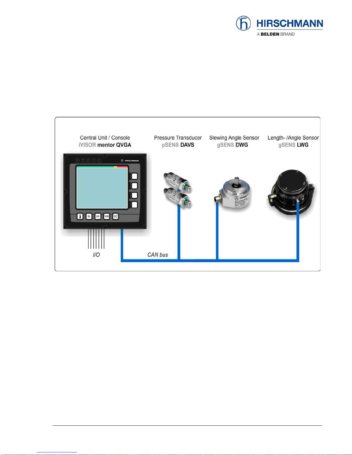
3. SYSTEM DESCRIPTION
The iVISOR mentor QVGA load moment indicator system comprises a central microprocessor unit
with an integrated display and control console together with various sensors to record the measured
values.
Fig. 1: Components of the iVISOR mentor QVGA LMI system (without optional extras)
The system operates on the principle of reference/real comparison. The actual value is compared
with the calculated reference values and evaluated by the system. An overload warning signal is
triggered on the display and operating console once limit values are reached. All crane movements
that increase the load moment are switched off at the same time.
The crane-specific data specified by the manufacturer, such as load capacity charts, boom weights,
centers of gravity and dimensions, are stored in the central data memory. This data is the reference
information used to calculate the operating conditions.
The boom angle and length is measured by means of an length/angle sensor that is mounted on the
boom. The crane load is determined indirectly with the aid of pressure transducers.
The operating console is located in the operator's cab in plain view of the crane operator. All displays
and operating elements have background illumination for enhanced ease of recognition. The console
contains various operating elements as well as a multifunction LC display, all of which are described
in detail in chapter 3.2
The contrast of the LC display is adjustable manually in accordance with ambient light levels.
Introduction
© 2009 Hirschmann Automation and Control GmbH · Branch Office Ettlingen · eMail: info.ec[email protected]e · www.hirschmann.com 6
24 183 19 1012e (Generic) / 2009-02-26 / Rev. 01 / rk.
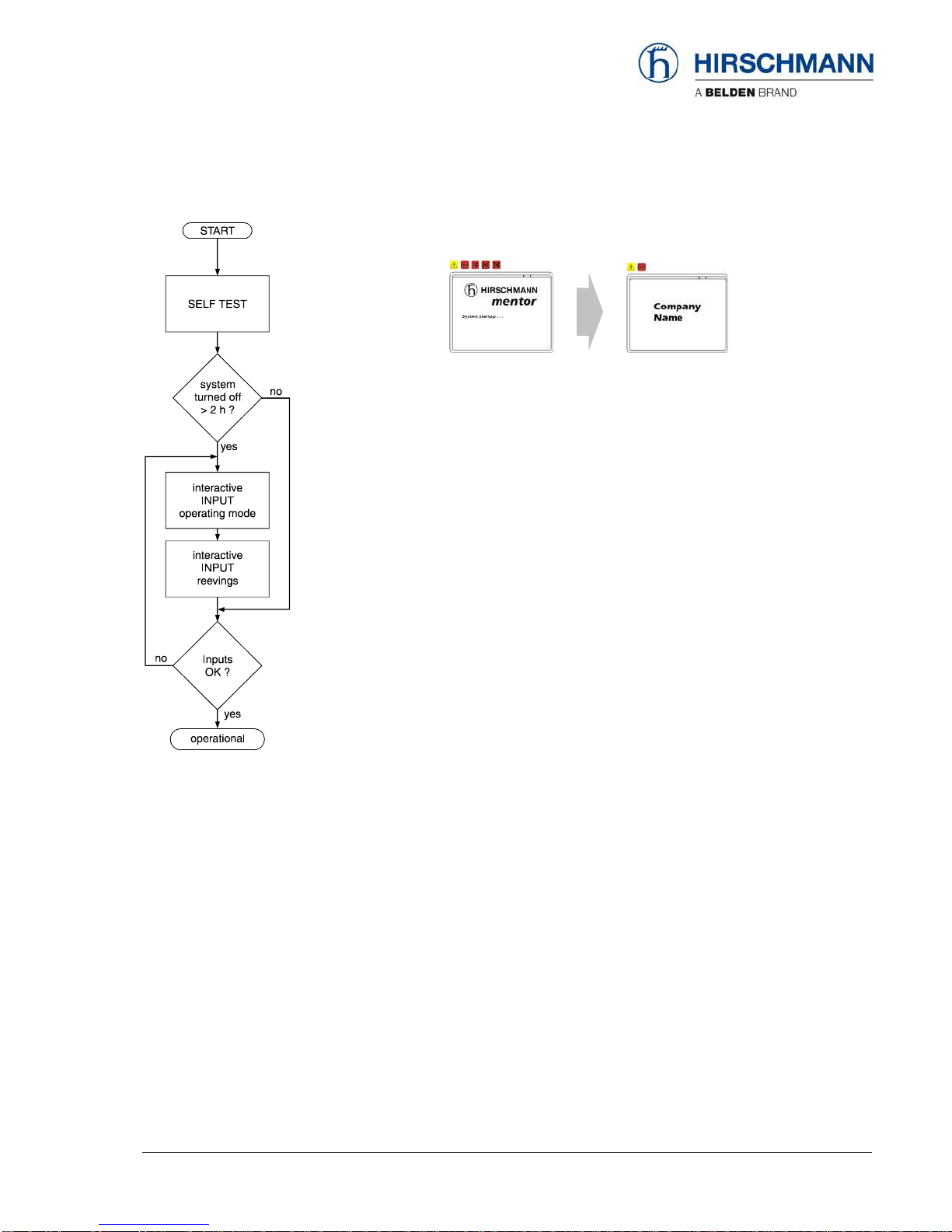
3.1 System start
Upon switching on, the system boots and starts with an automatic test of the LMI system,
lamps and audible alarm. During the test, the LC display shows the start screen.
If the system was turned off for more than two hours, the setup configuration has to be
entered after the system test. (⇒chapter 4)
First, the operating mode is determined by an interactive step-by-step interrogation of the
rigging states.
Next is the interactive input of the reeving.
Now the LC display shows all inputs and awaits acknowledgment or cancelling.
Upon acknowledgment of the inputs the system is ready for operation.
In the event of a malfunction, a corresponding error code "E##" will appear on the Data
display (1). (> refer to error code table)

Introduction
© 2009 Hirschmann Automation and Control GmbH · Branch Office Ettlingen · eMail: info.ec[email protected]e · www.hirschmann.com 7
24 183 19 1012e (Generic) / 2009-02-26 / Rev. 01 / rk.
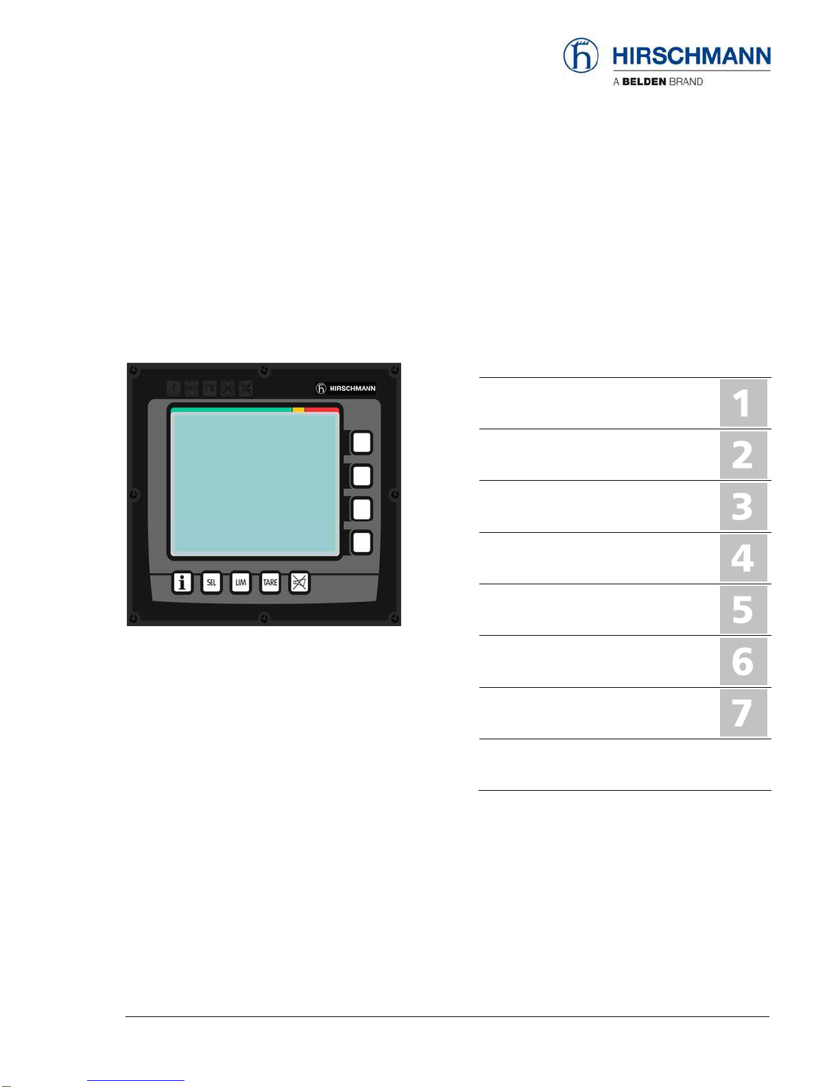
3.2 Displays and controls
The illustration shows the displays and controls of the iVISOR mentor QVGA console. The numbers
in the illustration correspond to the numbers in the following functional description for each item.
1 Data display (background lit)
2 Bar graph (utilisation)
3 Prewarning light
4 Overload warning light (load moment)
5 Hoist limit warning light (A2B)
6 “LMI bypass” warning light (flashes if bypassed)
7 "A2B bypass" warning light (flashes if bypassed)
8 Function keys F1 ... F4
9 “Info" key (system information)
10 System setup button
11 “LIM” button (working area definition)
12 “Tare” button
13 “Alarm off” button
Displays and controls
© 2009 Hirschmann Automation and Control GmbH · Branch Office Ettlingen · eMail: info.ec[email protected]e · www.hirschmann.com 8
24 183 19 1012e (Generic) / 2009-02-26 / Rev. 01 / rk.
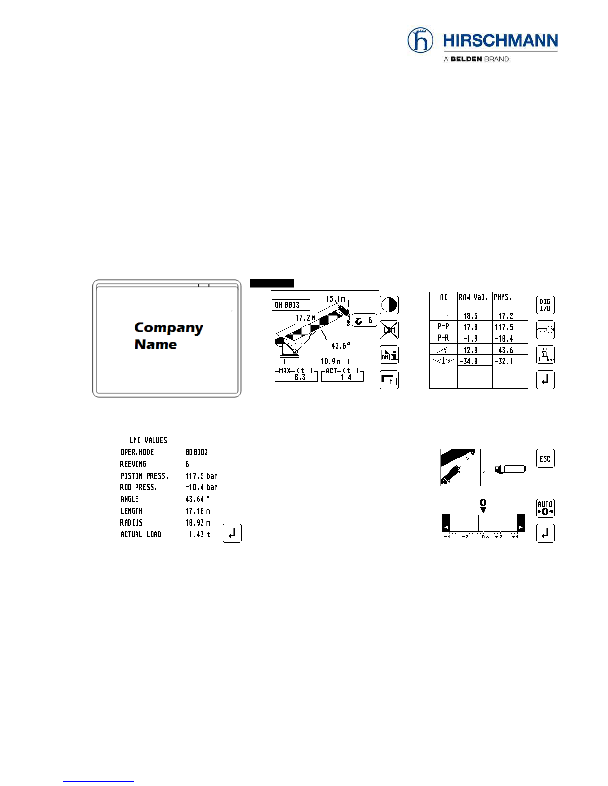
(1) Data display
The Data display (1) is dot matrix LC display with background illumination and extended temperature
range, on which essential data are displayed depending on the operating mode, such as load values,
geometry and crane data, symbols etc. The design enables good legibility even in bright sunlight,
and at night too thanks to the integrated background lighting.
Examples of display menus (values are not real)
Start after system test Display, normal operation Entry to Info menu
Display of LMI values Entry menu – working area definition Service menu (code-protected)
Pressure sensor adjustment
You can find a detailed description of symbols and displays in the chapters and the appendix of this manual.
Displays and controls
© 2009 Hirschmann Automation and Control GmbH · Branch Office Ettlingen · eMail: info.ec[email protected]e · www.hirschmann.com 9
24 183 19 1012e (Generic) / 2009-02-26 / Rev. 01 / rk.
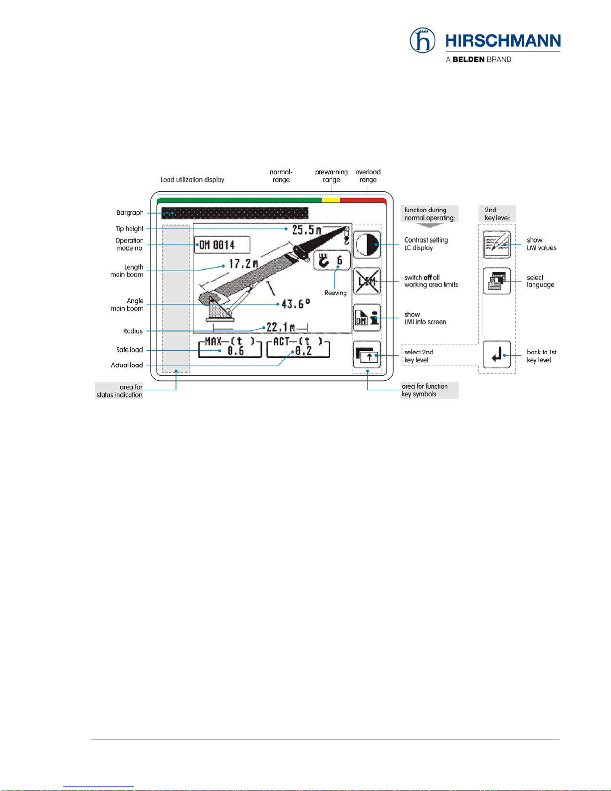
Data display (example w/o man basket):
Notes:
•If required, various symbols are displayed in the “status indication” field (refer to chapter 3.3).
•If required, active working area limits are displayed by the relevant symbols.
The relevant symbol flashes if the limit value is reached or exceeded.
•In the “function key symbols" field, the symbol allocated to the relevant function key appears.

Displays and controls
© 2009 Hirschmann Automation and Control GmbH · Branch Office Ettlingen · eMail: info.ec[email protected]e · www.hirschmann.com 10
24 183 19 1012e (Generic) / 2009-02-26 / Rev. 01 / rk.
(2) Utilisation display (bar graph)
The Utilisation display (bar graph) indicates how much of
the admissible load moment (rated moment) is used. As the
rated moment changes constantly during loader operation,
the load moment display also changes constantly.
The utilisation display is marked with differently coloured fields:
green: "Safe” operation (0...90% of rated moment)
yellow: “Prewarning range” (90...100% of rated moment)
red: “Overload range” (> 100% of rated moment)
(3) “Pre-warning” light
When this amber display light comes on, this indicates that
the utilisation of the crane has reached the specified pre-
warning range. An overload situation could therefore be
imminent!
At the same time, the acoustic alarm sounds an interrupted
signal.
For the crane operator, this means that the work can
only be continued with caution.
(4) “Overload” warning light
This red display light lights up to indicate that the maximum
capacity has been reached or exceeded.
At the same time, the acoustic alarm sounds an
uninterrupted signal and, depending on the system wiring,
load moment-increasing boom movements are stopped.
By actuating the key the acoustic alarm can be
suppressed after a minimum 5-second warning.
Displays and controls
© 2009 Hirschmann Automation and Control GmbH · Branch Office Ettlingen · eMail: info.ec[email protected]e · www.hirschmann.com 11
24 183 19 1012e (Generic) / 2009-02-26 / Rev. 01 / rk.
(5) "Hoist limit” warning light (A2B)
This red warning light lights up when the hoist limit switch
contacts open, i.e. when a hoist limit situation has occurred.
The acoustic alarm sounds and load-moment-increasing
crane movements are switched off at the same time.
A hoist limit situation occurs when the hook block
comes into contact with the boom head. The danger
exists in such situations that the hoist rope will
break, causing the load to fall. A hoist limit situation
could arise from the load being pulled against the
boom head or from the boom being extended or
lowered without the hoist rope being spooled off the
winch.
(6) “LMI bypass” warning light
This warning light flashes when the cut-out function of the
LMI system has been manually bypassed.
(7) “Hoist limit switch bypass” warning light
This red warning light lights up when the switch-off function
of the hoist limit switch has been manually bypassed.
Displays and controls
© 2009 Hirschmann Automation and Control GmbH · Branch Office Ettlingen · eMail: info.ec[email protected]e · www.hirschmann.com 12
24 183 19 1012e (Generic) / 2009-02-26 / Rev. 01 / rk.
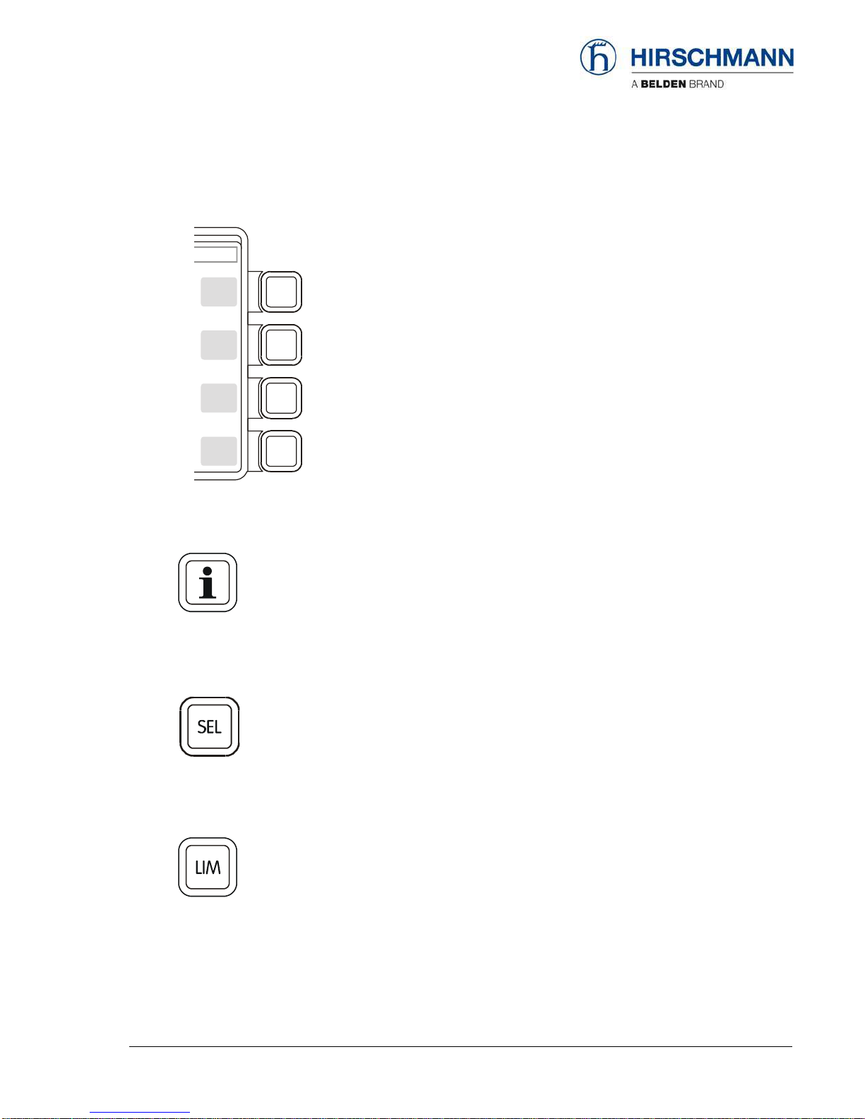
(8) Function keys F1 ... F4
Function keys with the allocated symbol.
During normal operation
(9) “Info” key
Key to bring system information and service menus.
Refer to chapter 5 and chapter 6.2.
(10) “SEL” key
Key to set up LMI system.
Refer to chapter 4.
(11) “LIM” key
Key to set up working area limits.
Refer to chapter 4.3

Displays and controls
© 2009 Hirschmann Automation and Control GmbH · Branch Office Ettlingen · eMail: info.ec[email protected]e · www.hirschmann.com 13
24 183 19 1012e (Generic) / 2009-02-26 / Rev. 01 / rk.
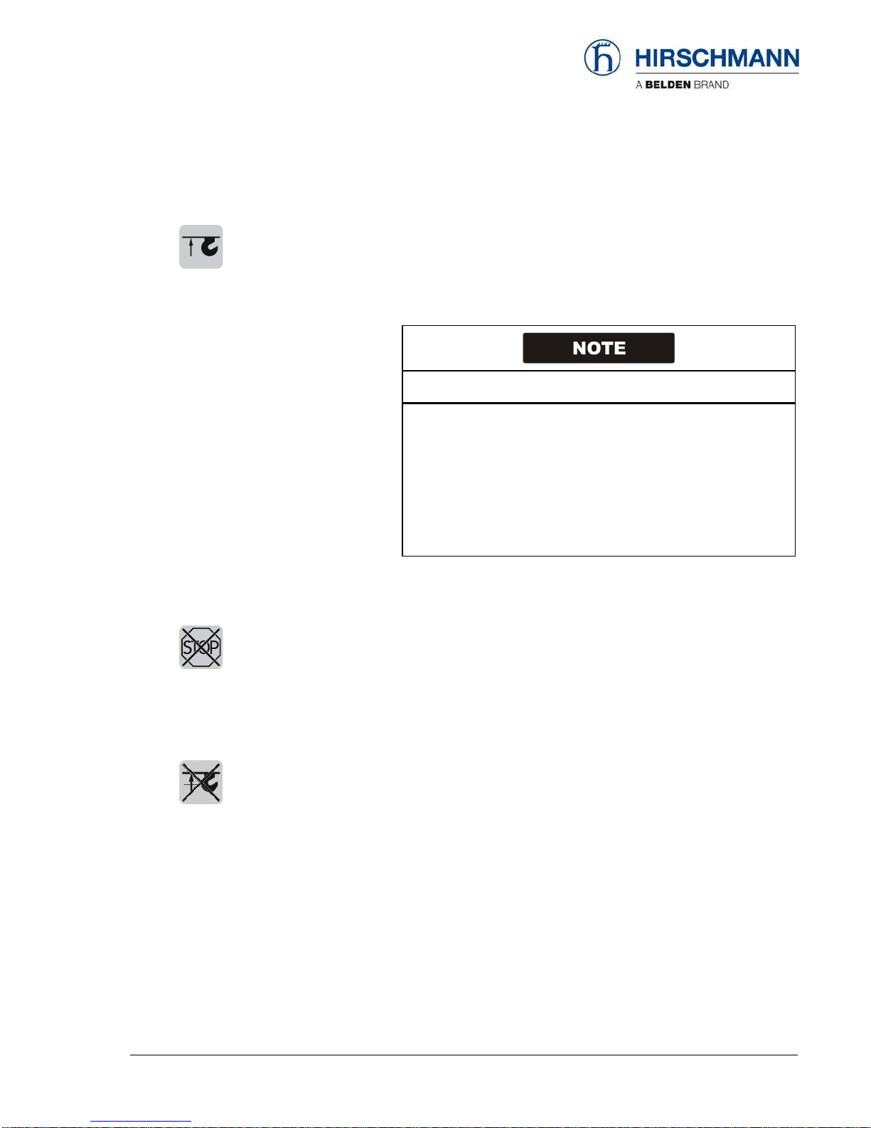
(12) “Tare” key
The “TARE” key is used to display the net load on the actual
load display. The net load is the actual load less the lifting
gear and hook block. The “TARE” key must be pressed
before the lift process starts.
After actuation, the current load display is reset to zero (tared). After lifting
the load, the actual load display shows the net load (working load). Once
the working radius changes (due to a change of angle or radius), the
display changes back to the actual load and the tare function is ended.
NOTE: The actual load includes the load suspension device, the lifting
cable and all load limit stop equipment. The net load is the current load
without any load limit stop equipment. Display errors can be caused by
environmental factors, e.g. wind on the boom or load.
(13) “Alarm acknowledge” key
When this key is pressed, the acoustic alarm can be
suppressed after sounding for at least 5 secs.
After around 10 secs., the alarm sounds again if the reason
which triggered the alarm is still present.
The acoustic alarm sounds in the following cases:
System test, overload status, LMI system fault, and operating errors
detected by the system.
Displays and controls
© 2009 Hirschmann Automation and Control GmbH · Branch Office Ettlingen · eMail: info.ec[email protected]e · www.hirschmann.com 14
24 183 19 1012e (Generic) / 2009-02-26 / Rev. 01 / rk.
3.3 Status displays
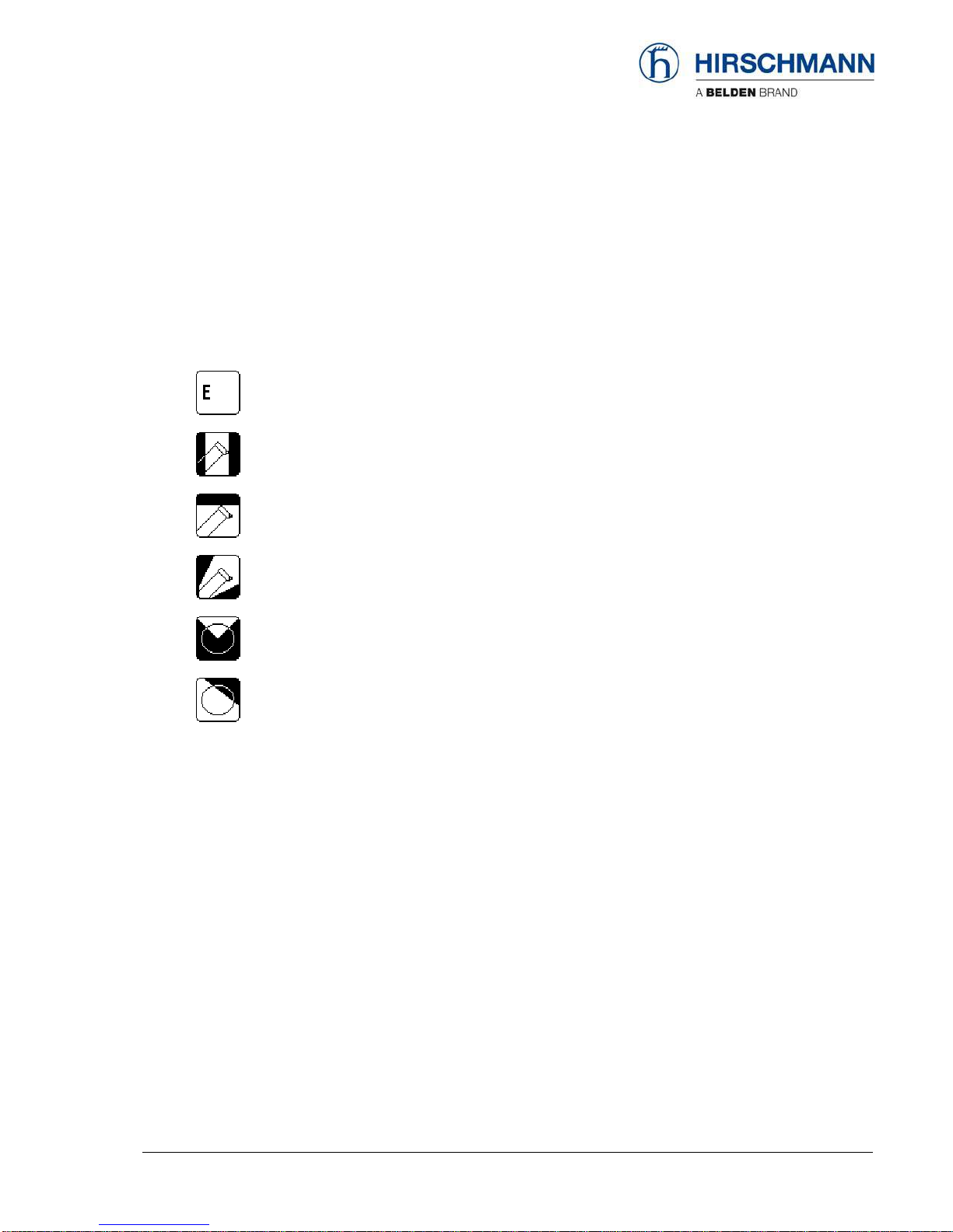
If required, various symbols are displayed in the “status area” of the data display (1).
Some of the symbols flash depending on the operating status.
LMI error in combination with a code (refer to error code list)
Constant: radius monitoring active Flashing: limit reached or exceeded.
Constant: height monitoring active Flashing: limit reached or exceeded.
Constant: boom angle monitoring active Flashing: limit reached or exceeded.
Constant: slew angle monitoring active Flashing: limit reached or exceeded.
Constant: virtual wall monitoring active Flashing: limit reached or exceeded.
Configuration Setup
© 2009 Hirschmann Automation and Control GmbH · Branch Office Ettlingen · eMail: info.ec[email protected]e · www.hirschmann.com 15
24 183 19 1012e (Generic) / 2009-02-26 / Rev. 01 / rk.
4. Configuration SETUP
The configuration setup procedure allows the operator to input the crane configuration using
interactive displays.
The LMI cannot perform correctly unless it has been properly adjusted. The prerequisite for
this is making conscientious and correct entries during the setup procedure, in accordance
with the actual configuration of the crane. The accuracy of the LMI settings must be
ensured before beginning crane work in order to avoid damage to property and severe or
even fatal injuries to personnel.
The correct setting is of utmost importance for the proper functioning of the system and the
crane.
Therefore, only operators who are thoroughly familiar with the crane and the operation of
the system should execute this configuration procedure.
4.1 Interactive operation mode setup
It is necessary to setup the mode of operation of the LMI system every time the crane structure has
been changed or if the system has been turned off for more than 2 hours.
If the system was switched off, for example during short breaks (less than 2 hours), all adjustments
remain stored. When switching on again the system these adjustments can be acknowledged by
merely pressing the "Enter" key (provided that the crane configuration has not been modified!).
During the programming procedure the Load Moment Pre-warning Light (3) and the Load Moment
Limit Light (4) will light up and the aggravating crane movements will be interrupted.
The LMI programming procedure consists of the following steps (interactive operation):
•setting the boom type configuration
•specify jib / selecting man basket /
•setting outrigger configuration
•specify working range
•setting option: stowed jib operation
•setting hoist
•setting reevings
•confirming of inputs
For easy operation, the computer guides the operator through the procedure step by step.
Configuration Setup
© 2009 Hirschmann Automation and Control GmbH · Branch Office Ettlingen · eMail: info.ec[email protected]e · www.hirschmann.com 16
24 183 19 1012e (Generic) / 2009-02-26 / Rev. 01 / rk.
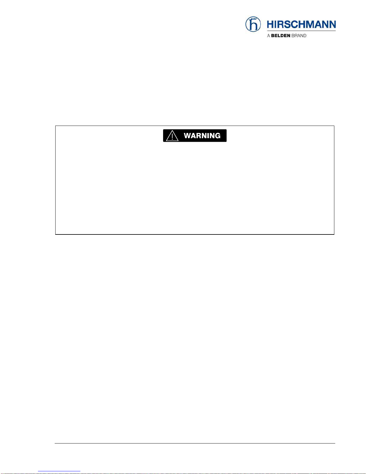
Calling up the function: (automatically with system restart if shut down time longer than 2 hours ago)
Actuate "SEL" key
Overview menu with symbols appears, with any previously programmed
limits. In this menu screen, the operator is prompted to confirm the
previous made entries or to renew the setup.
The system will temporarily interrupt the movements of the crane during the
setup procedure.
Check the displayed values before confirming them!
•Start setup procedure or confirm previous settings:
Setup reeving
START configuration setup procedure
OK, only if all entries are correct
The entering of the mode of operation code is completed after this confirmation,
and the normal operation screen is displayed.
•Select main boom with or without man basket:
1=boom operation 2=man basket operation
Cursor to next position
Cursor to previous position
Confirm selection, go to next step
>

Configuration Setup
© 2009 Hirschmann Automation and Control GmbH · Branch Office Ettlingen · eMail: info.ec[email protected]e · www.hirschmann.com 17
24 183 19 1012e (Generic) / 2009-02-26 / Rev. 01 / rk.
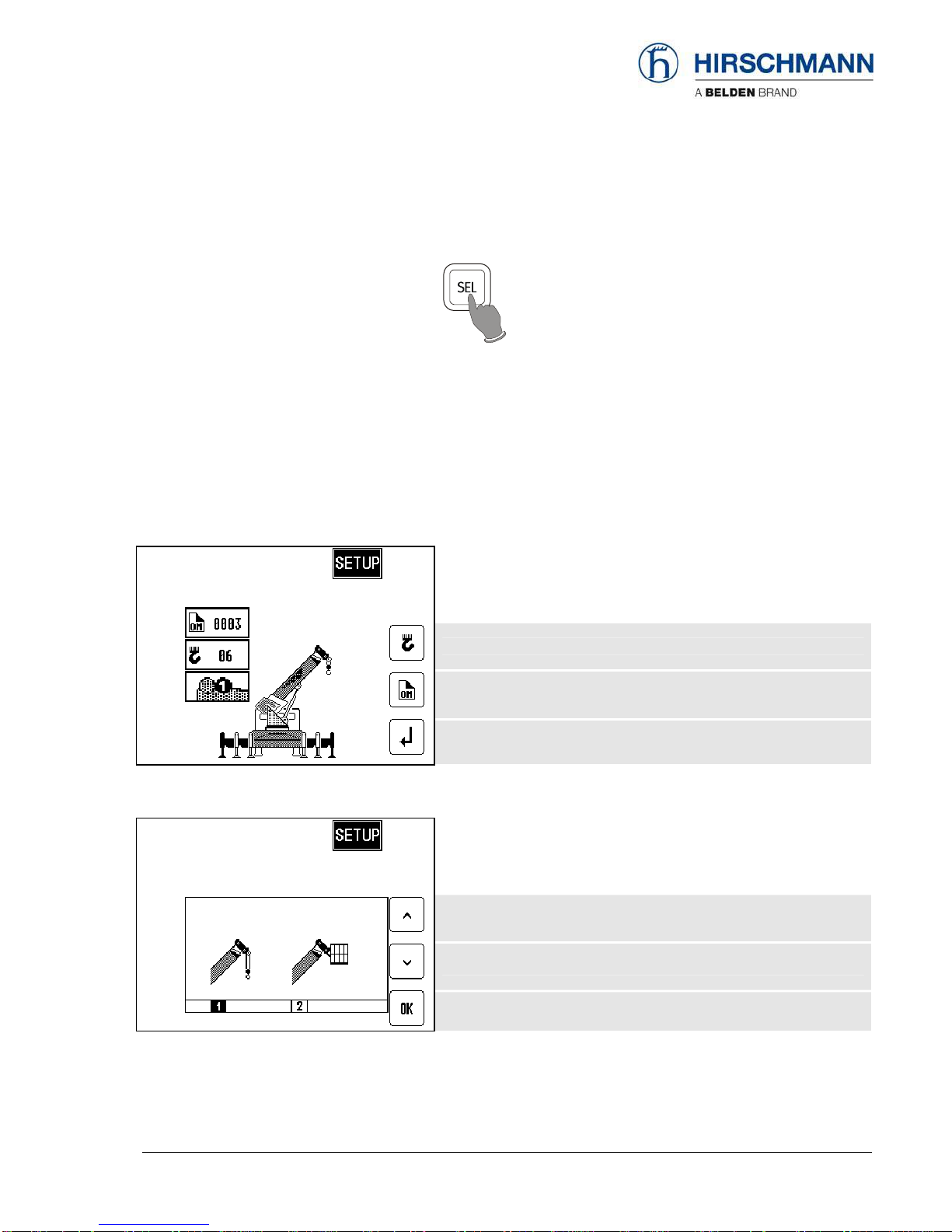
•Select boom with or without jib:
1=main boom 2=Main boom with jib
Cursor to next position
Cursor to previous position
Confirm selection, go to next step
•Select jib length:
(if jib operation was selected)
1=short jib 2=long jib
Cursor to next position
Cursor to previous position
Confirm selection, go to next step
•Select jib offset angle:
1=offset 1 2=offset 2 3=offset 3
Cursor to next position
Cursor to previous position
Confirm selection, go to next step
Configuration Setup
© 2009 Hirschmann Automation and Control GmbH · Branch Office Ettlingen · eMail: info.ec[email protected]e · www.hirschmann.com 18
24 183 19 1012e (Generic) / 2009-02-26 / Rev. 01 / rk.
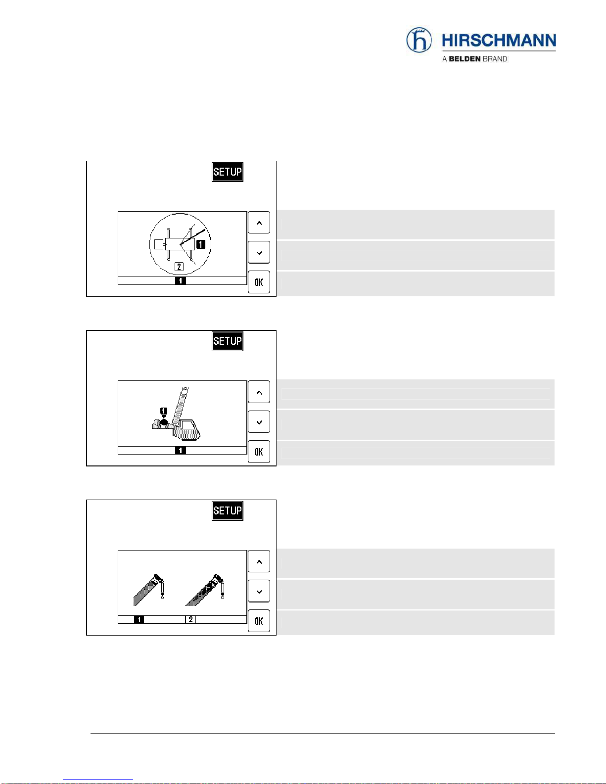
•Select working area:
1=over front 2=360°
Cursor to next position
Cursor to previous position
Confirm selection, go to next step
•Select hoist:
1=main hoist 2=auxiliary hoist
Cursor to next position
Cursor to previous position
Confirm selection, go to next step
•Select boom with or without stowed jib: (not with man basket operation)
1=main boom 2=man boom with stowed jib
Cursor to next position
Cursor to previous position
Confirm selection, go to next step
Configuration Setup
© 2009 Hirschmann Automation and Control GmbH · Branch Office Ettlingen · eMail: info.ec[email protected]e · www.hirschmann.com 19
24 183 19 1012e (Generic) / 2009-02-26 / Rev. 01 / rk.
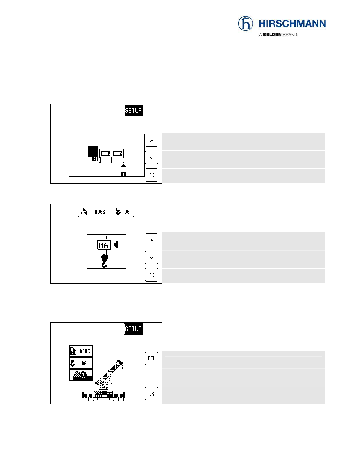
•Select outrigger position: (not with man basket operation)
1=max 2=mid 3=min 4=on rubbers
Cursor to next position
Cursor to previous position
Confirm selection, go to next step
•Select reeving:
(not with man basket operation)
Increase value
Decrease value
Confirm reeving, go to next step
•Confirm inputs:
In this menu screen (example), the operator is prompted to confirm the entries once again.
Please check the displayed values before confirming them!
Discard settings and renew setup procedure
OK, only if all entries are correct
The setup procedure is completed after confirmation.
The normal operation screen is displayed.
Configuration Setup
© 2009 Hirschmann Automation and Control GmbH · Branch Office Ettlingen · eMail: info.ec[email protected]e · www.hirschmann.com 20
24 183 19 1012e (Generic) / 2009-02-26 / Rev. 01 / rk.
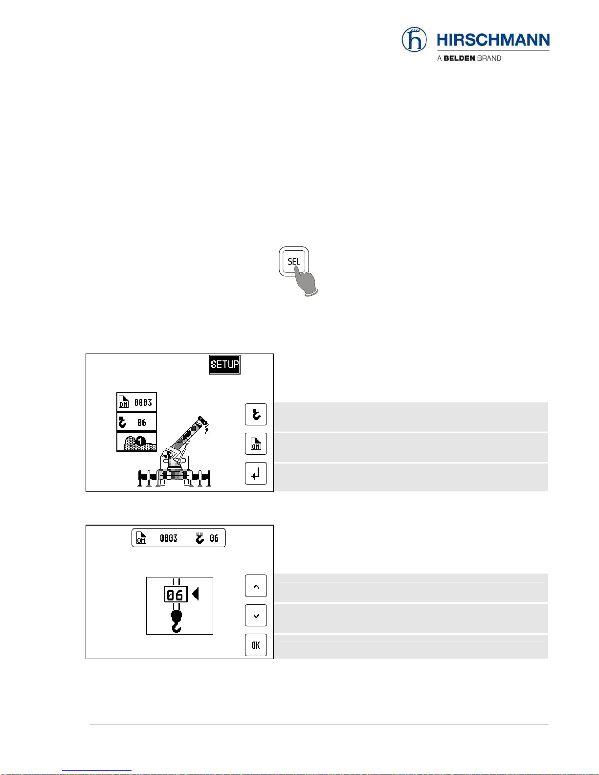
4.2 Quick adjusting the reeving
It is necessary to program the system by entering the respective number of reevings each time the
rope reeving arrangement is modified.
Calling up the function:
Actuate "SEL" key
The system will temporarily interrupt the movements of the crane during the
setup procedure.
•Start setup procedure
Note: Start of setup reeving procedure is not possible with man masket
operation!
Setup reeving
START configuration setup procedure
OK, only if all entries are correct
The entering of the mode of operation code is completed after this confirmation,
and the normal operation screen is displayed.
•Select reeving:
(not with man basket operation)
Increase value
Decrease value
Confirm reeving
Other manuals for iVISOR mentor QVGA
1
Table of contents
Other Hirschmann Touch Panel manuals

Hirschmann
Hirschmann PAT IFLEX5 User manual

Hirschmann
Hirschmann PRS 80 Wind Speed User manual

Hirschmann
Hirschmann PAT EI65/0005 User manual

Hirschmann
Hirschmann Mentor EI65 User manual

Hirschmann
Hirschmann PAT DS 160 User manual

Hirschmann
Hirschmann PAT DS 350GM Programming manual

Hirschmann
Hirschmann MARK 4E/2 User manual

Hirschmann
Hirschmann qSCALE maestro User manual

Hirschmann
Hirschmann iVISOR mentor QVGA User manual


