Hirschmann PRS 80 Wind Speed User manual

www.hirschmann.com
P/N 031-300-190-184 REV. C 05/23/06
PRS 80 Wind Speed
OPERATOR’S / SERVICE MANUAL


PRS 80 Wind Speed Operator’s/Service Manual
© Hirschmann ECS, 2006; PRS 80 Wind Speed Rev.C 05/23/06 190184_C
NOTICE
Hirschmann ECS makes no warranty of any kind with regard to this material, including, but not limited
to, the implied warranties of merchantability and/or its fitness for a particular purpose.
Hirschmann ECS will not be liable for errors contained in this manual or for incidental or consequential
damages in connection with the furnishing, performance, or use of this manual. This document
contains proprietary information, which is protected by copyright, and all rights are reserved.
No part of this document may be photocopied, reproduced, or translated to another language without
the prior written consent of Hirschmann ECS.
Hirschmann ECS reserves proprietary rights to all drawings, photos and the data contained therein.
The drawings, photos and data are confidential and cannot be used or reproduced without the written
consent of Hirschmann ECS. The drawings and/or photos are subject to technical modification without
prior notice.
All information in this document is subject to change without notice.
MANUAL REVISIONS
REV DATE NAME DESCRIPTION
- 02/04/05 CSH ECN 04-152
A 06/17/05 SB ECN 05-109
B 08/19/05 SB ECN 05-150
C 05/23/06 SB ECN 06-096

PRS 80 Wind Speed Operator’s/Service Manual
© Hirschmann ECS, 2006; PRS 80 Wind Speed Rev.C 05/23/06 190184_C
4

PRS 80 Wind Speed Operator’s/Service Manual
© Hirschmann ECS, 2006; PRS 80 Wind Speed Rev.C 05/23/06 190184_C
TABLE OF CONTENTS
1GENERAL INFORMATION.............................................................................................................1
2WARNINGS .................................................................................................................................... 1
3FEATURES ..................................................................................................................................... 2
4SYSTEM DESCRIPTION................................................................................................................ 2
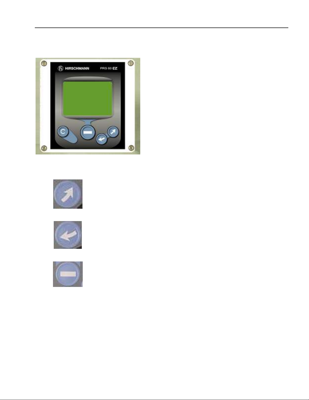
4.1 OPERATING CONSOLE ................................................................................................................... 2
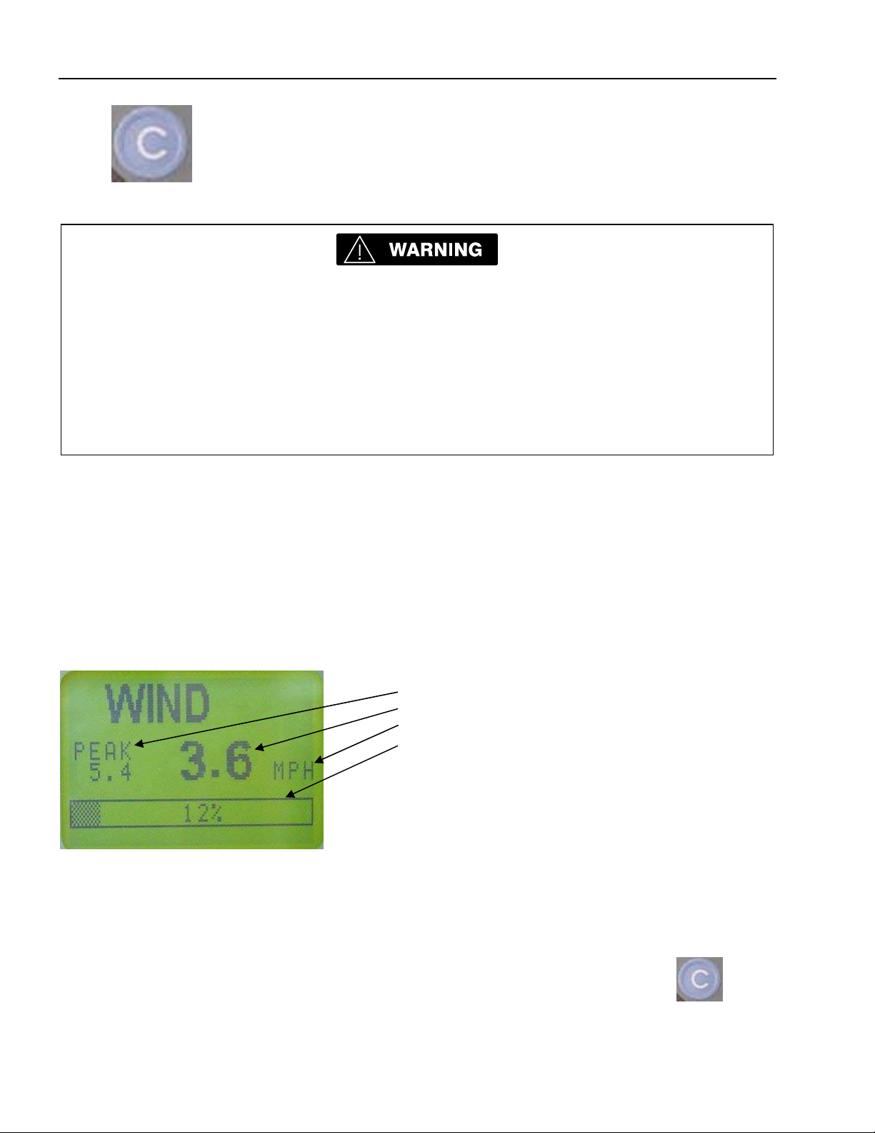
4.1.1 Liquid Crystal Display ...........................................................................................................................2
4.1.2 Control Identification .............................................................................................................................3
5SYSTEM OPERATION ................................................................................................................... 4
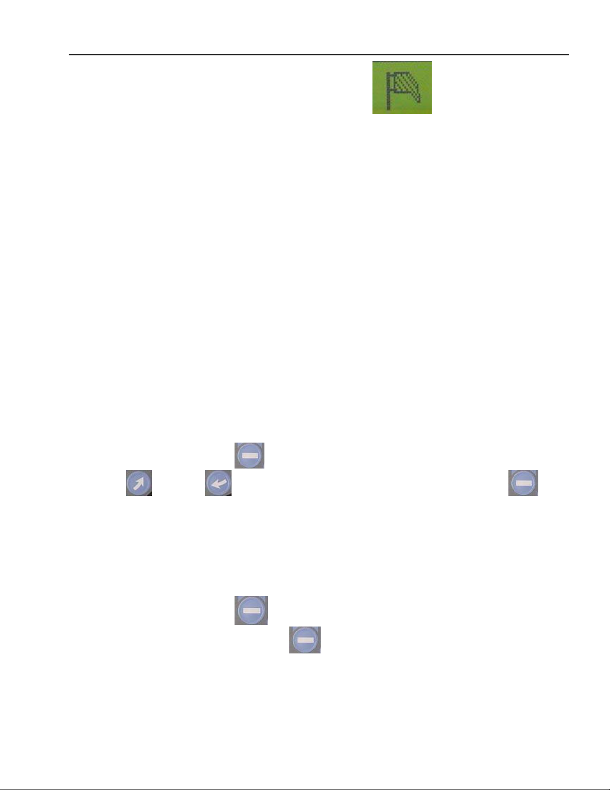
5.1 MENU'S ....................................................................................................................................... 5
5.2 MENU SELECTION INSTRUCTIONS .................................................................................................. 5
5.3 LIMITS........................................................................................................................................... 5
6INSTALLATION AND SETUP ......................................................................................................... 6
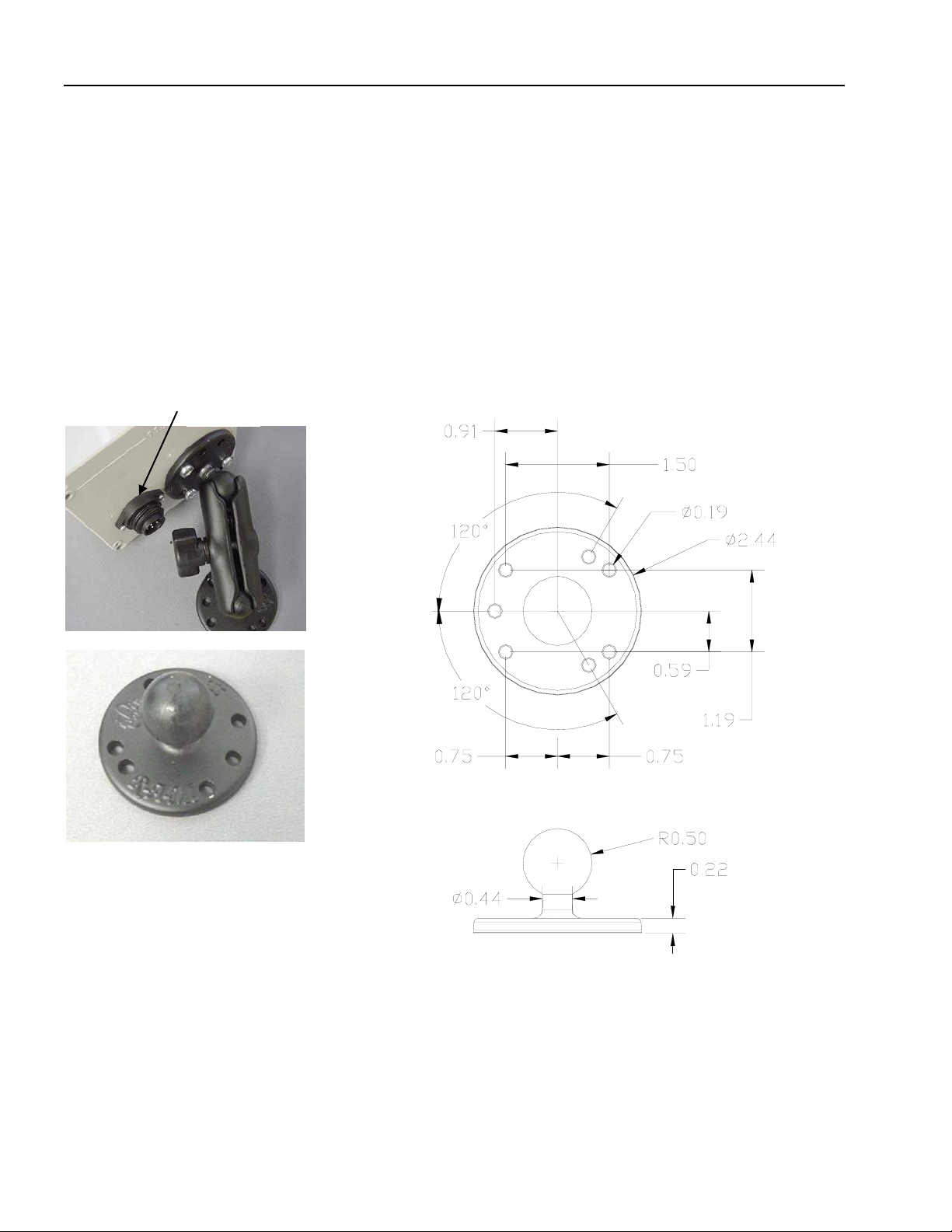
6.1 CONSOLE MOUNTING .................................................................................................................... 6
6.2 WIRING ......................................................................................................................................... 7
6.3 ADDING SENSORS.......................................................................................................................... 8
6.4 WIND SPEED SENSOR ................................................................................................................... 9
7SERVICE / TROUBLESHOOTING ............................................................................................... 10
7.1 SCREENS .................................................................................................................................... 11
7.2 DIAGNOSTICS .............................................................................................................................. 11
7.2.1 To Test the Display:............................................................................................................................11
7.2.2 To Test the buttons:............................................................................................................................12
7.2.3 To Test the outputs:............................................................................................................................12
7.3 NO DISPLAY ................................................................................................................................13
7.4 TROUBLESHOOTING MOISTURE.................................................................................................... 13
7.5 TROUBLESHOOTING CHART ......................................................................................................... 14
8MAINTENANCE ............................................................................................................................ 15
8.1 BATTERY REPLACEMENT ............................................................................................................. 15
9PART NUMBERS.......................................................................................................................... 16


General Information
© Hirschmann ECS, 2006; PRS 80 Wind Speed Rev.C 05/23/06 190184_C
1
1 GENERAL INFORMATION
The Hirschmann ECS PRS 80 System has been designed to provide indication from a various types of
radio sensors. To simplify operation, this PRS 80 console set up for wind speed only, but can be
software upgraded to indication other various types of radio sensors, i.e. A2B, Load, and Angle.
System limits can be set by the user; when these limits are exceeded the system will warn the
operator by sounding an audible alarm, flashing the backlit LCD and de-energize the lockout relay.
A system relay can be connected to the cranes lockout system to provide a lock out when exceeding
any of the user limits. The defining the lock out connections are the responsibly of the crane owner.
2 WARNINGS
The Hirschmann ECS PRS 80 System is an operational aid, which warns a crane operator of
approaching two-block conditions, which could cause damage to equipment and personal injury.
This device is not, and must not be a substitute for good, sound operator judgment, experience and
use of accepted safe crane operating procedures.
The responsibility for the safe operation of the crane remains with the crane operator who must ensure
that all warnings and instructions supplied are fully understood and observed.
Prior to operating the crane, the operator must carefully and thoroughly read and understand the
information in this manual to ensure that the operation and limitations of the system and the crane are
known.
The system can only work correctly, if all sensors/transmitters have been properly set. For
correct setup, the operator has to answer thoroughly and correctly all questions asked
during the setup procedure in accordance with the real rigging state of the crane. To prevent
material damage and serious or even fatal accidents, the correct adjustment of the system
has to be ensured before starting the crane operation.
Always refer to operational instructions and load charts provided by the crane manufacturer
for specific crane operation and load limits.

PRS 80 Wind Speed Operator’s/Service Manual
© Hirschmann ECS, 2006; PRS 80 Wind Speed Rev.C 05/23/06 190184_C
2
3 FEATURES
The Hirschmann ECS PRS 80 has the following features:
•Easily and clearly shows the operator required information.
•Multi language. The system can be setup to display text in both English and Spanish.
•Multiple limits can be set.
•Wireless operation.
•Minimum of 500 feet LOS.
•Frequency Hopping Spread Spectrum transceivers
•Can display in multiple units.
•Built in lockout relay. Rated at 2 amps
•Analog display of % of limit on load cells and wind speed.
•Tare function.
•Low battery indication.
•Expandable
4 SYSTEM DESCRIPTION
4.1 Operating Console
The console has 2 functions:
•Accepts inputs from the crane operator (limits and setup)
•Displays important data and information from the sensors
The operator’s console should be mounted in the operator’s field of vision.
4.1.1 Liquid Crystal Display
The Liquid Crystal Display (LCD) used in the Hirschmann ECS PRS 80 console is a wide temperature-
range graphic display with transflective characteristics that give it a high visibility in sunlight and during
backlit night operation. Due to the nature of any LCD, it works on the principle of polarization of light. It
should be noted that dual polarizations that are at a certain angle to each other can reduce the
amount of light up to completely eliminating it if that angle becomes perpendicular. This can have
significance if the operator is wearing polarized sunglasses that happen to be perpendicularly
polarized in relation to the LCD’s polarization. In this rare case, the operator has to work without
sunglasses or find different sunglasses that do not have this characteristic, in order to avoid having the
visibility of the display impaired.
The LCD contains an automatic temperature compensation that will adjust the LCD’s contrast
according to the surrounding temperature.

System Description
© Hirschmann ECS, 2006; PRS 80 Wind Speed Rev.C 05/23/06 190184_C
3
4.1.2 Control Identification
This unit contains a display and different controls that are described as follows:
Fig 2: Operator’s Console
1. LCD
2. Clear button
3. Select button
4. Up Button
5. Down Button
Button “SCROLL UP”
•Use this button to increase values or to scroll up.
•Changes which sensors are displayed and how each is displayed.
Button "SCROLL DOWN"
•Use this button to decrease values or to scroll down.
•Changes which sensors are displayed and how each is displayed
Button "SELECT"
•Use this button to enter the menu screen and to confirm selections.

PRS 80 Wind Speed Operator’s/Service Manual
© Hirschmann ECS, 2006; PRS 80 Wind Speed Rev.C 05/23/06 190184_C
4
Button "C"
•Generally used to back out of a selection and return to the previous
screen.
•While pushing this button, the control lever lockout function of the
system can be deactivated.
•Accesses the Tare function
Since button C can deactivate the lockout function of the system, the following instructions
must be obeyed:
•The by-pass function shall be used with discretion, as unwarranted use of it to override
the control lever lockout system can result in harm to the crane and danger to property
and persons.
•Never use the by-pass function to either overload or operate the crane in a non-
permissible range.
5 SYSTEM OPERATION
When switching on crane ignition switch, the system starts with an automatic test of the system, of
lamps and audible alarm. During the test, the LC display shows the console and system software
version. After the testing is complete, the main operating screen will be displayed.
If the wind speed requires setup (installed), refer to the Installation and Setup Section 6.3 sensors
procedure allows the operator to input the sensors being used and the limits for the sensors. The
operator must complete the setup procedure for each sensor.
The speed can be shown in miles per hour, or kilometers per hour.
The % of limit is shown at the bottom.
The peak will be the highest wind speed recorded since the system was started. When the system is
turned off the peak value will be reset. The peak value can also be reset by pressing the
button.
PEAK VALUE
CURRENT WIND SPEED
UNITS
% of LIMIT

System Operation
© Hirschmann ECS, 2006; PRS 80 Wind Speed Rev.C 05/23/06 190184_C
5
Here is the wind speed sensor icon displayed in the system. Wind Speed Sensor
5.1 MENU'S
LIMITS
SETUP
♦SENSORS
WIND SPD
INSTALL NEW
UNINSTALL
ENABLE / DISABLE
♦SCREEN/BEEPER
UNITS
•LBS - MPH
•KG - KPH
LANGUAGE
PCT BAR IS ON/OFF
WARNING ARE ON/OFF
♦DIAGNOSTICS
SCREEN
KEYPAD
OUTPUTS
ALARM LOG
COMM DATA
LOW BATTERIES (This will only be shown if a low battery condition exists)
ABOUT
5.2 Menu Selection Instructions
From the operating screen, press to enter the menu selection.
Use the up and down to scroll through and high light your selection then press to
make the selection.
5.3 Limits
The system sets the default speed limit to 30 mph. This is represented in by the bar graph. The bar
graph shows the % of the limit that is set. The limit can be set to other values.
To change the default limit, press , and then select the sensor for the limit that you want to set.
Use the arrows to change the value. Use the to confirm the values.
Note: a prewarning can be set so as to beep the alarm when a limit is approached but not reached.
This is set with the warning option. Menu- SETUP/ SCREEN/BEEPER/ WARNING.

PRS 80 Wind Speed Operator’s/Service Manual
© Hirschmann ECS, 2006; PRS 80 Wind Speed Rev.C 05/23/06 190184_C
6
6 INSTALLATION AND SETUP
6.1 Console Mounting
The console has a mount that allows the console to be swiveled into any direction and to be mounted
in a variety of locations and on nearly any surface.
Choose a location that is in line of site of the sensor and within reach of the operator. Securely attach
the base of the mounting apparatus onto a solid surface. The console has a mount that allows the
console to be swiveled into any direction and to be mounted in a variety of locations and on nearly any
surface.
The power supply can be from 12- 24 volt DC. The lockout wire supplies power to operate external
solenoids, or relays. The rating of the lockout is 2 amps. An internal fuse protects against overloading
this circuit.
Powe
r

Installation and Setup
© Hirschmann ECS, 2006; PRS 80 Wind Speed Rev.C 05/23/06 190184_C
7
6.2 Wiring
The wiring at the console connection is:
Pin # Description
#1- Power 10-30VDC
#2- Ground
#3- Lockout NO 2 amp max
#4- Lockout NC 2 amp max
#5- Lockout common 2 amp max
#6- Option

PRS 80 Wind Speed Operator’s/Service Manual
© Hirschmann ECS, 2006; PRS 80 Wind Speed Rev.C 05/23/06 190184_C
8
6.3 Adding sensors
To add a new sensor,
Menu- SETUP/SENSORS/
This gives the sensor select/information screen. It shows the status of all hardware. In the example
below "NOT IN." means that none of the sensors are installed.
Sensor status screen.
Choose the sensor that you wish to install and follow the onscreen instructions, which will ask you to
remove the paper tap insulating the battery contact or installing the batteries into the transmitter. To do
this, remove the 4 screws from the transmitter housing and remove the paper insulation tag that reads
“REMOVE BEFORE OPERATION” by holding the batteries in place with one hand and removing the
tag with the other or insert batteries, if not installed.
LOOSEN 4 SCREWS

Installation and Setup
© Hirschmann ECS, 2006; PRS 80 Wind Speed Rev.C 05/23/06 190184_C
9
6.4 Wind Speed Sensor
The sensor is delivered with a bracket support that allows the sensor to stay perpendicular to the
ground through the boom angle range.
CONTACT CRANE MANUFACTURER FOR WELDING INSTRUCTIONS PRIOR TO WELDING
ON BOOM.
The mounting pole is affixed to the boom tip at your discretion so that the anemometer sensor is
mounted approximately a foot higher than the boom sheaves and will not interfere or be damaged by
hoist lines or extension mounting or movement. Affix the mounting pole to the boom tip or possibly the
length cable anchor pin so the pipe supports the sensor. It must be installed so that no part of the
crane can disrupt the measurement of wind.

PRS 80 Wind Speed Operator’s/Service Manual
© Hirschmann ECS, 2006; PRS 80 Wind Speed Rev.C 05/23/06 190184_C
10
7 SERVICE / TROUBLESHOOTING
Daily maintenance of the system consists of inspecting:
1. The electrical wiring connecting the various parts of the system.
If electrical wiring is damaged, it shall be replaced immediately.
2. If the insulation is worn on the electrical wiring or cable guides are damaged, these parts shall be
replaced.
3. A damaged or punctured display must be replaced immediately to prevent ingress of water and
damage to the internal circuitry.
Other than correcting the problems identified in the Malfunctions Table and replacing faulty
mechanical parts and cables, no other repairs shall be performed by non-expert personnel.
When the Hirschmann ECS PRS 80 system is turned on, it will show the following screen. This screen
shows the telephone number of Hirschmann ECS and the software version.
Make sure the display is working and all the lights come on during this time. Listen to the buzzer
sound. If any of the components above fails, please contact your nearest service representative before
operating the system!

Service / troubleshooting
© Hirschmann ECS, 2006; PRS 80 Wind Speed Rev.C 05/23/06 190184_C
11
7.1 Screens
Communication error screen
This screen shows that there is an error in the communication between the sensor / sensors and the
console. The sensor that is in error is indicated with the icon at the bottom of the screen. In the
example, both the load and the A2B 1 are in error. Only the sensors that communication error are
shown.
7.2 Diagnostics
There are several diagnostics screens that can be accessed thru the display. However, it is possible
that a malfunction can cause the displays to be inaccessible. In this case follow the troubleshooting
section of the manual.
7.2.1 To Test the Display:
Menu- SETUP/ DIAGNOSTICS/ SCREEN.
Various test screens will be displayed by pressing the button. Press to go to
the next screen. Note any problems in the display.

PRS 80 Wind Speed Operator’s/Service Manual
© Hirschmann ECS, 2006; PRS 80 Wind Speed Rev.C 05/23/06 190184_C
12
7.2.2 To Test the buttons:
Press
Menu- SETUP/ DIAGNOSTICS/ BUTTONS.
When a button is pressed, the corresponding button on the console will invert. Press each button one
at a time. When finished, press and hold "C".
7.2.3 To Test the outputs:
Press
Menu- SETUP/ DIAGNOSTICS/ OUTPUTS.
Arrow to select an output to test. Press to test the selected output. The state of the output will
change when the button is pressed. The status indicator text will also change when the
button is pressed.

Service / troubleshooting
© Hirschmann ECS, 2006; PRS 80 Wind Speed Rev.C 05/23/06 190184_C
13
7.3 No Display
The only time you should need to open the console is when there is power to the console and the
display is blank. If you find it necessary to open the console, inspect the gasket for damages and
replace it if necessary, refer to Section 7.4 Troubleshooting Moisture.
With power to the console you should see the following:
If the LED’s, are not working, replace the console. Note: the 2A fuse protects output relay in case
current over draw. The board is protected by a 0.5A resettable fuse.
7.4 Troubleshooting Moisture
The receiver contains electronic components and has an IP65 protection rating. These electronic
components cannot be designed to withstand exposure to moisture over a longer period of time. If you
find water or moisture inside any of the housings, the source for the water ingress has to be detected
and corrected to ensure proper operation.
There are two major possibilities for the occurrence of excessive moisture inside an enclosure:
1) Water ingress; caused by a cracked or broken housing or lid, or a defective gasket.
2) Condensation
This outline gives instructions for detecting the cause for excessive moisture by using simple
troubleshooting methods and how to prevent the moisture ingress from happening again.
Indicator LED's
RED = POWER
FLASHING GREEN = OK

PRS 80 Wind Speed Operator’s/Service Manual
© Hirschmann ECS, 2006; PRS 80 Wind Speed Rev.C 05/23/06 190184_C
14
7.5 Troubleshooting Chart
After the onboard diagnostics have been performed, follow these guidelines
All LED's are located inside the receiver box.
Problem Cause Solution
LCD does not light
or show characters.
No power to console Make sure the console is getting power from the crane.
Check wiring.
Ensure correct polarity of the power.
Open console, check status of LED's. Both the red and
green LED's should be on.
LCD does not
function properly
Faulty LCD Go into the diagnostics screen for the display. Verify all
screens are functioning.
If any of the tests fail, replace console
Buttons do not
work
Faulty buttons If possible, go to the diagnostics screen for the buttons.
Test the function of each button.
If any of the buttons fail, replace the console.
Communication
error
Low battery Verify which sensor is causing the error by looking at the
icons on the communication error screen.
Replace batteries.
Communication
error
Faulty sensor Verify which sensor is causing the error by looking at the
icons on the communication error screen.
Verify that the LED on the sensor is blinking.
Communication
error
Poor reception Verify which sensor is causing the error by looking at the
icons on the communication error screen.
Verify that the LED on the sensor is blinking.
Verify that the sensor is line of sight to the console.
Communication
error
Sensor not installed. Install the sensor on the console. See adding sensors
Communication
error
Poor communication
caused by
interference.
Remove potential interference sources from the area.
Mount the receiver in a different location.
Horn does not
sound
Faulty Go into the diagnostics screen for the outputs. Verify all
outputs are functioning.
If any of the tests fail, replace console.
Crane functions
locked out all the
time
Incorrect wiring Check for power to lockout device.
Crane functions
locked out all the
time
Communication error. See communication error.
Crane functions
locked out all the
time
Fault in receiver
module.
Check relay output voltage on wire number 3.
Transmitter LED
does not flash
Sensor is asleep. Pull switch wire rope. Red LED will flash ~each 2 sec.
Replace batteries.
Replace transmitter.
Table of contents
Other Hirschmann Touch Panel manuals

Hirschmann
Hirschmann MARK 4E/2 User manual

Hirschmann
Hirschmann PAT EI65/0005 User manual

Hirschmann
Hirschmann PAT DS 350GM Programming manual

Hirschmann
Hirschmann Mentor EI65 User manual

Hirschmann
Hirschmann iVISOR mentor QVGA User manual

Hirschmann
Hirschmann iVISOR mentor QVGA User manual

Hirschmann
Hirschmann PAT IFLEX5 User manual

Hirschmann
Hirschmann qSCALE maestro User manual

Hirschmann
Hirschmann PAT DS 160 User manual