Hirschmann iVISOR mentor QVGA User manual

© 2009 Hirschmann Automation and Control GmbH · Branch Office Ettlingen · eMail: info.ec[email protected]e · www.hirschmann.com 1
24 183 69 1012e (Generic) / 2009-02-26 / Rev. 01 / rk.
iVISOR
mentor QVGA
Service Manual
Edition 2/2009 Rev. A
The order code for this document is
24 183 69 1012e (Generic)
Contents
General information
Important notes
Service menus
Troubleshooting
Appendix:
Wiring Diagrams …

© 2009 Hirschmann Automation and Control GmbH · Branch Office Ettlingen · eMail: info.ec[email protected]e · www.hirschmann.com 2
24 183 69 1012e (Generic) / 2009-02-26 / Rev. 01 / rk.
TABLE OF CONTENTS
1. General information ........................................................................... 3
2. Important notes .................................................................................. 5
3. Sensor calibration.............................................................................. 6
3.1 Zero-setting the pressure signals......................................................... 8
3.2 Zero-setting the slewing signal........................................................... 10
3.3 Length sensor calibration procedure.................................................. 12
3.4 Angle sensor calibration procedure.................................................... 15
4. Troubleshooting............................................................................... 19
4.1 General information............................................................................ 19
4.2 Error code list ..................................................................................... 20
Revision History ................................................................................. 26
Appendix: Wiring, Drawings, Spare Parts
The manufacturer reserves the right to modify the contents of this manual without notice. Hirschmann will not be liable for
errors contained in this manual or for incidental or consequential damages in connection with the furnishing, performance, or
use of this manual. This document contains proprietary information, which is protected by copyright, and all rights are
reserved. No part of this document may be photocopied, reproduced, or translated to another language without the prior
written consent of Hirschmann. Hirschmann reserves proprietary rights to all drawings, photos and the data contained
therein. The drawings, photos and data are confidential and cannot be used or reproduced without the written consent of
Hirschmann. The drawings and/or photos are subject to technical modification without prior notice.
All information in this document is subject to change without notice..

Configuration Setup
© 2009 Hirschmann Automation and Control GmbH · Branch Office Ettlingen · eMail: info.ec[email protected]e · www.hirschmann.com 3
24 183 69 1012e (Generic) / 2009-02-26 / Rev. 01 / rk.
1. GENERAL INFORMATION
This manual describes the service menus of the iVISOR mentor QVGA load moment indicator (LMI)
and assists a service or maintenance person in identifying system malfunctions.
NOTE: Knowledge of system and CAN bus wiring is assumed.
REFERENCE: Refer to Operator’s manual 24 183 19 1012e (Generic) for detailed operation of
the mentor QVGA.
The iVISOR mentor QVGA load moment indicator system comprises a central microprocessor unit
with an integrated display and control console together with various sensors to record the measured
values. The system components are connected via CAN bus.
Components of the iVISOR mentor QVGA LMI system

Configuration Setup
© 2009 Hirschmann Automation and Control GmbH · Branch Office Ettlingen · eMail: info.ec[email protected]e · www.hirschmann.com 4
24 183 69 1012e (Generic) / 2009-02-26 / Rev. 01 / rk.
Components:
CPU/Console: The iVISOR mentor QVGA load moment indicator comprises a central
microprocessor unit with an integrated display and operating console together with various
sensors to record measured values. The system components are connected via CAN bus.
The iVISOR mentor QVGA displays all geometrical information such as length and angle
of main boom, working radius and tip height of the boom. It also displays the actual load
and the maximum load permitted by load chart. Furthermore, it has an acoustical alarm, a
warning light for overload, and a pre-warning light.
The graphic display allows for a simple interactive configuration setup, as well as sensor
calibration (zero adjustment), and troubleshooting sensor output screen. The console has
a warning light for anti-two-block conditions and an override switch for overload or anti-
block condition.
Length-Angle Transducer: The length-angle sensor gSENS LWG, often referred to as
the “cable reel”, is a combination of two transducers in one box, installed on the base
section of the boom. It measures the length and the angle of the boom. A reeling drum
drives a potentiometer, which is the length transducer. Part of the length transducer circuit
is the length cable on the drum, which is a multi-conductor cable. It is connected to the
anti-two-block switch at the boom head and to a slip ring body in the LWG. The angle
transducer is a potentiometer driven by a weighted pendulum that is oil damped. Both
length and angle transducer are connected to a CAN bus controller board, which is
connected to the bus system.
Pressure Transducer(s): A pressure transducer pSENS DAVS converts hydraulic
pressure into a CAN signal. One (or two) pressure transducer is (are) connected to the
piston side of the lift cylinder and one to the rod side.
Slew Angle Sensor: The gSENS DWG sensor converts the circular motion of the upper
structure of the crane into a CAN signal.
Configuration Setup
© 2009 Hirschmann Automation and Control GmbH · Branch Office Ettlingen · eMail: info.ec[email protected]e · www.hirschmann.com 5
24 183 69 1012e (Generic) / 2009-02-26 / Rev. 01 / rk.
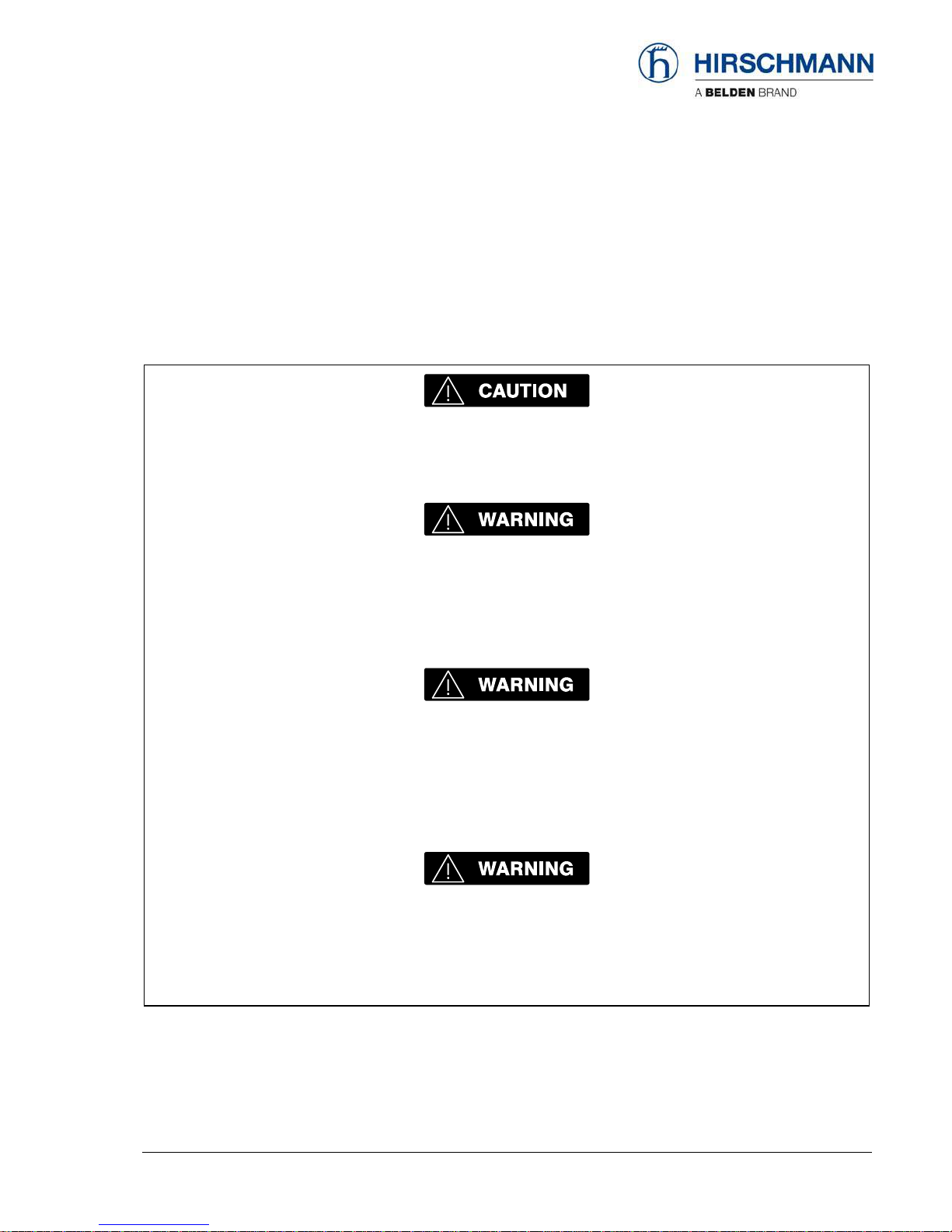
2. IMPORTANT NOTES
The LMI is an operating aid that warns the crane operator of imminent overloading or of the approach
of the hook block to the boom head, in order to avoid possible property damage or injury to personnel.
The device is not, nor is it intended to be, a substitute for good operator judgment and/or experience,
nor does it remove the need for utilizing only recognized safe procedures during crane operations.
The crane operator continues to bear ultimate responsibility for safe operation of the crane.
He must ensure that he fully understands and follows the displayed notes and instructions
in their entirety.
The LMI is not able to provide aid to the crane operator unless it has been properly adjusted
and unless the correct load capacity chart and the correct operating code have been
entered for the respective rigging configuration. The correctness of the LMI settings must
be guaranteed before beginning crane work in order to avoid damage to property and
severe or even fatal injuries to personnel.
This system can be equipped with an external key-operated switch located in the crane
operator's cab. This key-operated switch overrides control lever function switch-off by the
LMI or by the hoist limit switch system. This switch may only be used during emergency
situations, and even then only by authorized personnel. Failure to observe these
instructions could result in damage to property and severe or even fatal injuries to
personnel.
The LMI cannot perform correctly unless it has been properly adjusted. The prerequisite for
this is making conscientious and correct entries during the set-up procedure, in
accordance with the actual configuration of the crane. The correctness of the LMI settings
must be ensured before beginning crane work in order to avoid damage to property and
severe or even fatal injuries to personnel.

Sensor Calibration
© 2009 Hirschmann Automation and Control GmbH · Branch Office Ettlingen · eMail: info.ec[email protected]e · www.hirschmann.com 6
24 183 69 1012e (Generic) / 2009-02-26 / Rev. 01 / rk.
3. Sensor Calibration
In this code-protected area, settings affecting system precision can be made by trained service
personnel. For access to the calibration menus it is necessary to input a matching 5-digit code.
To start the function:
▼Info screen
Actuate the INFO key.
to service menus
back
▼Entry to calibration menus
abort input of service code
increase marked numeric value
reduce marked numeric value
mark the next figure, access after the last valid figure
If an invalid service code is entered, you are prompted to enter it again or to abort the input.

Sensor Calibration
© 2009 Hirschmann Automation and Control GmbH · Branch Office Ettlingen · eMail: info.ec[email protected]e · www.hirschmann.com 7
24 183 69 1012e (Generic) / 2009-02-26 / Rev. 01 / rk.
After entering the service menu you can follow the calibration procedure step by step or can select
the type of calibration by scrolling with function key . Press "ESC" to finish calibration procedure:
3.1) pressure
signal piston side
… and rod side 3.2) slewing angle
signal
3.3) boom length
signal
3.4) boom angle
signal

Sensor Calibration
© 2009 Hirschmann Automation and Control GmbH · Branch Office Ettlingen · eMail: info.ec[email protected]e · www.hirschmann.com 8
24 183 69 1012e (Generic) / 2009-02-26 / Rev. 01 / rk.
3.1 Zero-setting the pressure signals
NOTE: The only thing adjustable for the pressure transducers is the zero point, which is the signal the
transducer outputs when there is no (zero) pressure sensed.
Ensure there is no pressure in the hydraulic line when
disconnecting the hoses from pressure transducers!
The display shows which transducer (piston-side, rod-side or force) is being zeroed and a horizontal
dial marks the present pressure (or force) difference in %.
NOTE: there are two calibration screens: for piston and for rod transducer.
NOTE: The operating range for zero-setting this value is from -1% to +1%.
Press and release the “AUTO >CAL<” key multiple times until the zero-setting starts.
The indicator line must move to zero on the dial, otherwise the zero-setting of this value is not
correct!
▼Zero point adjustment, pressure piston side:
leave the service menu
carry out zero point setting
skip calibration step / go to next menu

Sensor Calibration
© 2009 Hirschmann Automation and Control GmbH · Branch Office Ettlingen · eMail: info.ec[email protected]e · www.hirschmann.com 9
24 183 69 1012e (Generic) / 2009-02-26 / Rev. 01 / rk.
▼Zero point adjustment, pressure rod side:
leave the service menu
carry out zero point setting
skip calibration step / go to next menu
Sensor Calibration
© 2009 Hirschmann Automation and Control GmbH · Branch Office Ettlingen · eMail: info.ec[email protected]e · www.hirschmann.com 10
24 183 69 1012e (Generic) / 2009-02-26 / Rev. 01 / rk.
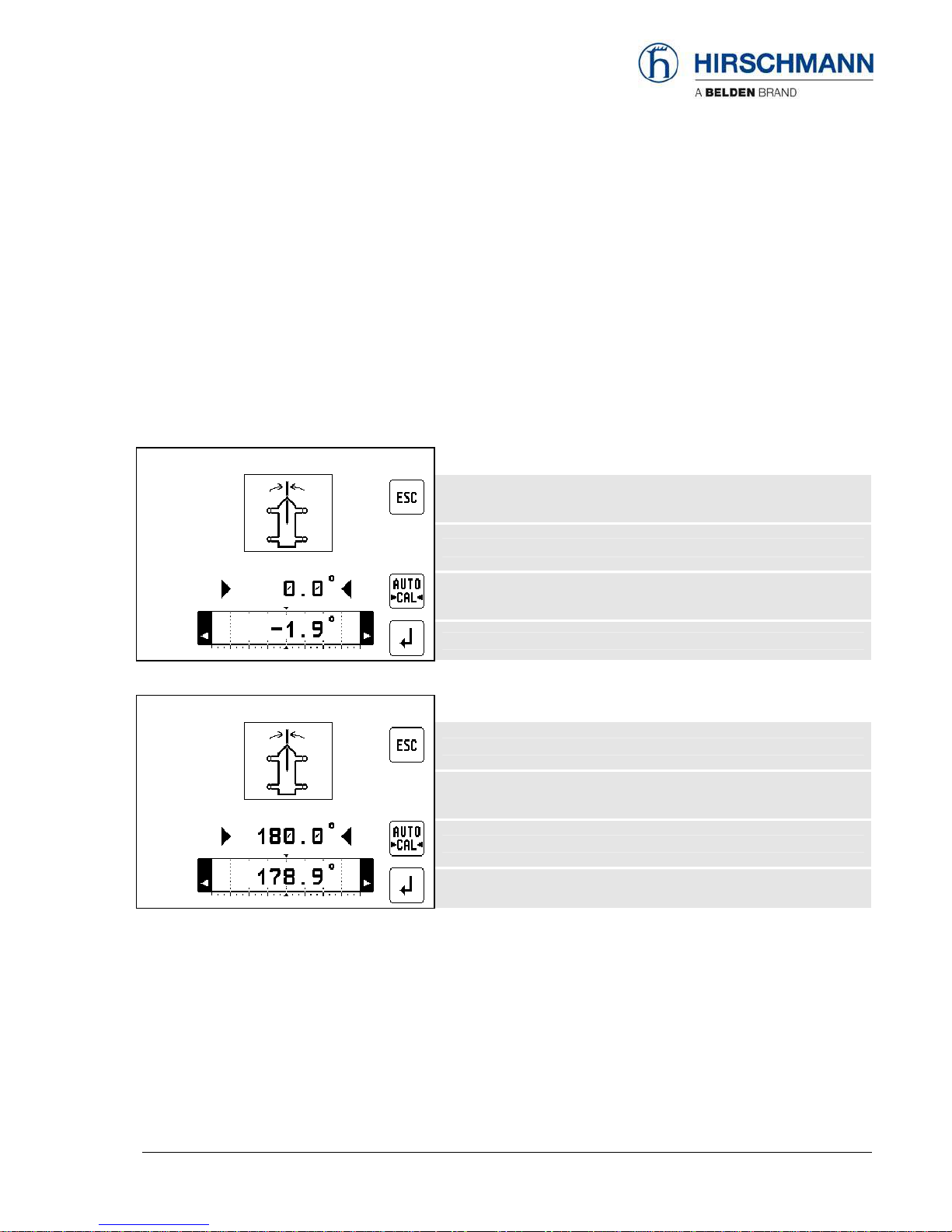
3.2 Zero-setting the slewing signal
NOTE: The only thing adjustable for the slew potentiometer is the zero point, which is complete when
the boom is at the 0°and 180° position of the crane.
NOTE: The range for zero-setting this value is from -10° to +10°./ ±170° to 190°
Press the “AUTO >CAL<” key until the zero-setting starts. The indicator line must move to zero
on the dial, otherwise the zero-setting of this value is not correct!
▼Zero point setting, slewing angle 0° position:
leave the service menu
carry out zero point setting slewing angle for 0° position
skip calibration step / go to next menu
▼Zero point setting, slewing angle 180° position:
leave the service menu
carry out zero point setting slewing angle for 180° position
skip calibration step / go to next menu
Sensor Calibration
© 2009 Hirschmann Automation and Control GmbH · Branch Office Ettlingen · eMail: info.ec[email protected]e · www.hirschmann.com 11
24 183 69 1012e (Generic) / 2009-02-26 / Rev. 01 / rk.
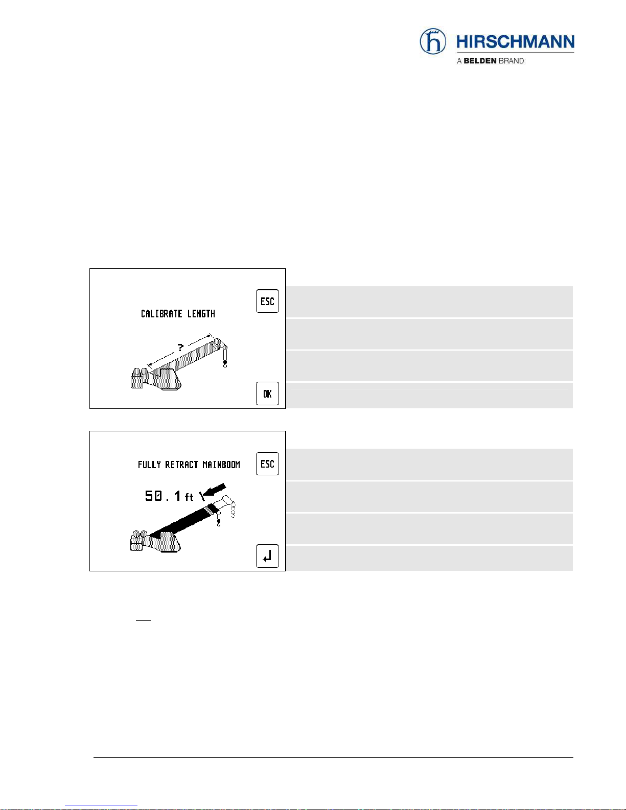
3.3 Length sensor calibration procedure
NOTE: The length sensor can be calibrated for its zero point and its full range.
With retracted boom, the potentiometer of the length sensor has to be at its 0 position, which is all the
way counter-clockwise. For extended boom, the adjustment is done by software as described below.
The length should be calibrated to be about 0.1 feet (or 0.05m for metric) accurate for retracted and
extended lengths. Perform the following steps:
▼Start screen zero point adjustment, boom length:
leave the service menu
Start length calibration
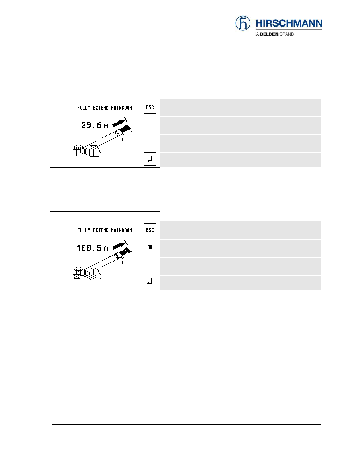
▼Start screen min. boom length:
leave the service menu
skip calibration step / go to next menu
•Fully retract the main boom and check if indicated length is within 0.1 feet (or 0.05m for metric) of
actual retracted boom length.
•If it is not, adjust length potentiometer mechanically as described below:
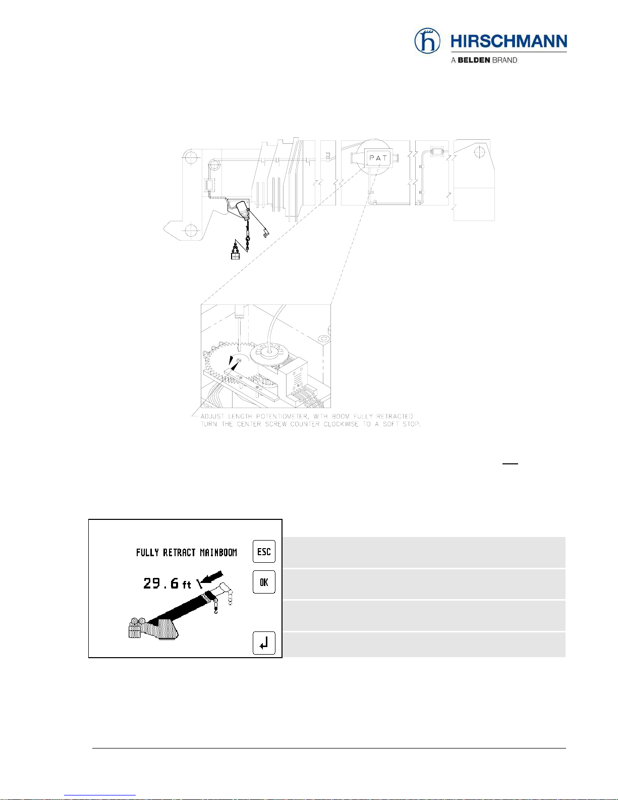
Sensor Calibration
© 2009 Hirschmann Automation and Control GmbH · Branch Office Ettlingen · eMail: info.ec[email protected]e · www.hirschmann.com 12
24 183 69 1012e (Generic) / 2009-02-26 / Rev. 01 / rk.
•With boom fully retracted turn the center screw of the length pot unit counter clockwise to a soft stop.
•During adjustment an additional button "OK" appears. Check value and set actual length as fully retracted
length by pressing OK.
▼Adjustment, min length:
leave the service menu
carry out min. boom length setting
skip calibration step / go to next menu
Afterward next calibration screen appears:
Sensor Calibration
© 2009 Hirschmann Automation and Control GmbH · Branch Office Ettlingen · eMail: info.ec[email protected]e · www.hirschmann.com 13
24 183 69 1012e (Generic) / 2009-02-26 / Rev. 01 / rk.
▼Start screen maximum. boom length:
leave the service menu
skip calibration step / go to next menu
•Now extend main boom all the way out. Make sure you are within the allowed operating range
(especially maximum radius).
•During telescoping out the boom an additional button "OK" appears.
▼Adjustment, maximum length:
leave the service menu
carry out max. boom length setting
skip calibration step / go to next menu
•Check whether boom is fully extended, then press "OK". Afterward next calibration step (angle)
appears.
Sensor Calibration
© 2009 Hirschmann Automation and Control GmbH · Branch Office Ettlingen · eMail: info.ec[email protected]e · www.hirschmann.com 14
24 183 69 1012e (Generic) / 2009-02-26 / Rev. 01 / rk.
3.4 Angle sensor calibration procedure
The angle sensor can be calibrated for its zero point, with steep boom (75°) and one or two additional
angle values (40° / 65°)
Material required: calibrated inclinometer
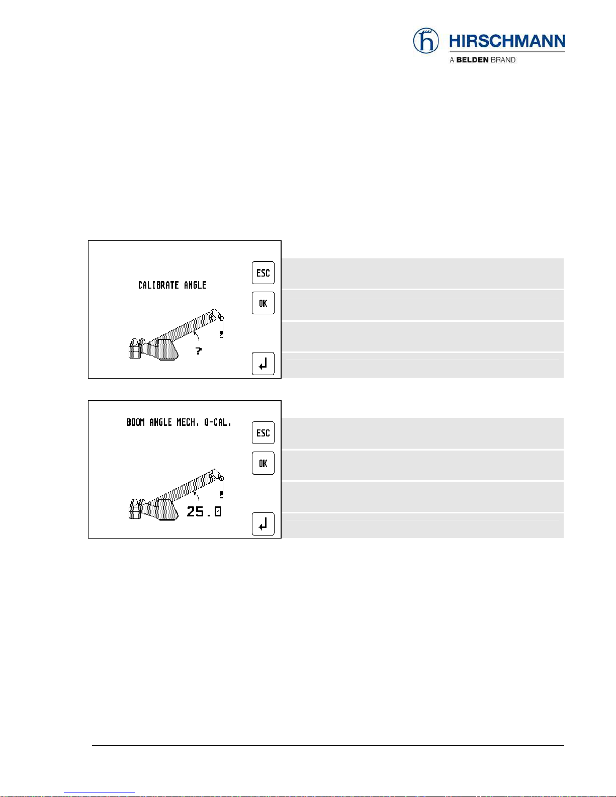
▼Start screen adjustment, boom angle:
leave the service menu
Start angle calibration procedure
▼Start calibration for "zero degree" angle:
leave the service menu
skip calibration step / go to next menu
Sensor Calibration
© 2009 Hirschmann Automation and Control GmbH · Branch Office Ettlingen · eMail: info.ec[email protected]e · www.hirschmann.com 15
24 183 69 1012e (Generic) / 2009-02-26 / Rev. 01 / rk.
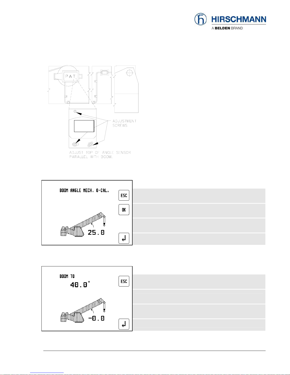
•Boom down.
•Release adjustment screws of the angle
sensor.
•Mechanically adjust top of angle sensor
housing exact parallel with boom by help of
inclinometer.
•Fix adjustment screws of the angle sensor.
Having adjusted the angle sensor mechanically check value and press "OK" for the next step.
▼Calibration for "zero degree" angle:
leave the service menu
calibrate next angle
skip calibration step / go to next menu
•Now boom up to 40°, (range is 35°- 45°)
▼Calibration for "40°" angle:
leave the service menu
calibrate next angle
skip calibration step / go to next menu
angle
sensor

Sensor Calibration
© 2009 Hirschmann Automation and Control GmbH · Branch Office Ettlingen · eMail: info.ec[email protected]e · www.hirschmann.com 16
24 183 69 1012e (Generic) / 2009-02-26 / Rev. 01 / rk.
When the boom angle is within the calibration range, the screen will add the
‘CHANGE ?’ / ‘SET’ and ‘OK’ text as shown below:
▼Calibration for "40°" angle:
leave the service menu
adjust actual angle
set current angle to defined angle
•Measure the boom angle with the inclinometer and when the boom is positioned in the calibration
range, compare the measured angle to the displayed angle.
•If the indicated angle is within +/- 0.1 degrees of the measured angle, confirm with ‘OK’.
Otherwise, select ‘SET’ to adjust the angle.
▼Adjust "40°" angle:
leave the service menu
increase angle value by 0.1°
Confirm
decrease angle value by 0.1°
•Once you push ‘SET’ , the screen is going to change to the angle adjustment screen. Use the ‘+’
and ‘-‘ buttons to adjust the indicated angle to match the measured angle.
•When the display shows the correct angle, press ‘OK’.
Press ESC to leave sensor adjustments and return to normal LMI screen.
•Now repeat procedure as shown for the boom angle 65° and 75°.
If values were modified a confirmation screen appears at the end:

Sensor Calibration
© 2009 Hirschmann Automation and Control GmbH · Branch Office Ettlingen · eMail: info.ec[email protected]e · www.hirschmann.com 17
24 183 69 1012e (Generic) / 2009-02-26 / Rev. 01 / rk.
▼Confirmation screen
leave the service menu
YES, I confirm
NO, go to next menu
•When you are sure to save this calibration, press ‘OK’. Normal LMI screen appears. Otherwise
press "Return" for restart the calibration procedure
Press ESC to leave sensor adjustments and return to normal LMI screen.

Troubleshooting
© 2009 Hirschmann Automation and Control GmbH · Branch Office Ettlingen · eMail: info.ec[email protected]e · www.hirschmann.com 18
24 183 69 1012e (Generic) / 2009-02-26 / Rev. 01 / rk.
4. TROUBLESHOOTING
4.1 General information
In the event of a malfunction, if the range is not reached or is exceeded or if an operating error is
detected by the system, a message appears on the data display (1) starting with an “E” followed by a
two-digit code which indicates the reason for the malfunction.
The error codes listed in the following table describe the various error codes which can be displayed
in this system.
Faults in the microprocessor system must be dealt with only by the manufacturer’s trained customer
service personnel. If faults occur, please contact Hirschmann Service USA:
www.hirschmann.com > USA > Electronic Control Systems > Contact - ECS.

Error Code List
© 2009 Hirschmann Automation and Control GmbH · Branch Office Ettlingen · eMail: info.ec[email protected]e · www.hirschmann.com 19
24 183 69 1012e (Generic) / 2009-02-26 / Rev. 01 / rk.
4.2 Error code list (System program LSQN V 1.11)
Error Code Error Cause Elimination
E01 Fallen below radius
range or angle range
exceeded
•Fallen below the minimum
radius or gone past the
maximum angle specified in the
respective load chart due to
luffing up the boom too far
•Luff down the boom to a radius
or angle specified in the load
chart.
E02 Radius range exceeded
or fallen below angle
range
•Gone past the maximum radius
or fallen below the minimum
angle specified in the respective
load chart due to luffing down
the boom too far
•Luff up the boom to a radius or
angle specified in the load
chart.
E03 Non-permitted slewing
zone (no load area)
•The slewing zone with load is
not permitted
•Slew to permitted area
•A non existing operating mode
has been selected
•Set the correct operating mode
for the operating state in
question
E04
Operating mode not
acknowledged or non
permitted slewing zone •The boom is in a non-permitted
slewing zone
•Slew the boom to a permitted
area.
•Boom has been extended either
too far or not far enough, e.g. if
it is prohibited to go beyond a
certain maximum boom length
or with load curves for jibs
where the main boom has to be
extended to a certain length
•Extend/retract boom to the
correct length
•Length sensor adjustment has
changed, e.g. the cable slid off
the length sensor reel.
•Retract boom. Check the pre-
stress of the cable reel (cable
must be taut). Open the length
sensor and carefully turn the
length sensor pot
counterclockwise until the
detent by means of a screw
driver
E05
Prohibited length range
•Clutch between length sensor
pot and drive is defective
•Replace the complete clutch
including drive wheel and adjust
length sensor pot as described
above
E06
Radius range exceeded
or fallen below angle
range with luffing jib
operation
•Maximum radius as specified in
the load chart exceeded or
fallen below minimum angle
due to luffing down the luffing
jib too far
•Luff the jib to a radius or angle
specified in the load chart.
•Length potentiometer is
defective
•PDB variable for analog value
not supported
•Replace length potentiometer
•Setup of correct PDB variable
for analog value in DGA6.i.3
E11
Fallen below lower limit
value for measuring
channel "length main
boom" •Electronic component in the
measuring channel is defective
•Replace sensor unit

Error Code List
© 2009 Hirschmann Automation and Control GmbH · Branch Office Ettlingen · eMail: info.ec[email protected]e · www.hirschmann.com 20
24 183 69 1012e (Generic) / 2009-02-26 / Rev. 01 / rk.
Error Code Error Cause Elimination
•Pressure transducer is
defective.
•PDB variable for analog value
not supported
•Replace pressure transducer
•Setup of correct PDB variable
for analog value in DGA6.i.3
E12
Fallen below the lower
limit value in the
measuring channel
"pressure piston side"
•Electronic component in the
measuring channel is defective.
•Replace sensor unit
E13
Fallen below lower limit
value in the measuring
channel "pressure rod
side"
•refer to E12 •refer to E12
E14
Fallen below lower limit
value in measuring
channel "force"
•Force transducer defective
•Electronic component in the
measuring channel is defective.
•Replace force transducer
•Replace sensor unit
•Angle potentiometer defective
•PDB variable for analog value
not supported
•Replace angle sensor
•Setup of correct PDB variable
for analog value in DGA6.i.3
E15
Fallen below lower limit
value in measuring
channel "angle main
boom"
•Electronic component in the
measuring channel defective.
•Replace sensor unit
•Angle potentiometer defective •Replace angle sensor
E16
Fallen below lower limit
value in measuring
channel "angle 2"
•Electronic component in the
measuring channel defective.
•Replace sensor unit
•Length potentiometer defective •Replace length sensor.
E17
Fallen below lower limit
value "length telescope I
(+II)"
•Electronic component in the
measuring channel defective
•Replace sensor unit
E18 Front outrigger
overloaded
•Front outrigger overloaded •
•Cable between the central unit
and the slewing angle sensor
defective or loose. Water inside
the plug of the angle sensor
•1-cannel slew sensor min. value
DGA 11.5.7 <> 0
•Check cable as well as plugs,
replace, if need be.
•move to allowed slew range
•Slewing angle potentiometer is
defective
•Replace slewing angle sensor
E1A
Fallen below lower limit
value in measuring
channel "slewing angle
1".
slew below allowed
range
•Electronic component in the
measuring channel defective
•Replace sensor unit
E1B
Fallen below lower limit
value in measuring
channel "slewing angle
2"
•refer to E1A
•refer to E1A
E1C Fallen below lower limit •Angle potentiometer defective •Replace angle sensor
Other manuals for iVISOR mentor QVGA
1
Table of contents
Other Hirschmann Touch Panel manuals

Hirschmann
Hirschmann PAT DS 350GM Programming manual

Hirschmann
Hirschmann PAT EI65/0005 User manual

Hirschmann
Hirschmann iVISOR mentor QVGA User manual

Hirschmann
Hirschmann PAT IFLEX5 User manual

Hirschmann
Hirschmann Mentor EI65 User manual

Hirschmann
Hirschmann PRS 80 Wind Speed User manual

Hirschmann
Hirschmann PAT DS 160 User manual

Hirschmann
Hirschmann MARK 4E/2 User manual

Hirschmann
Hirschmann qSCALE maestro User manual


