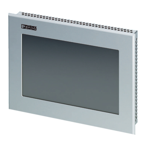
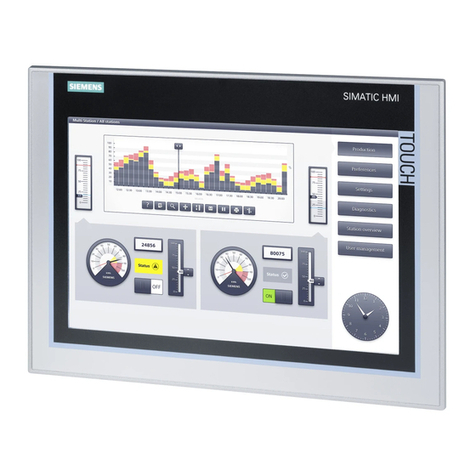
Hirschmann Mentor EI65 User manual

HIRSCHMANN
LENGTH-ANGLE-RADIUS-LOAD
INDICATING SYSTEM
Mentor EI65
OPERATOR’S MANUAL
P/N 190231, Rev. A, 12/22/09


Operator’s Manual Mentor EI65
© Hirschmann Automation and Control Rev. - 12/22/09 190231_A.doc
NOTICE
The information in this document is subject
to change without notice.
Hirschmann makes no warranty of any kind with regard
to this material, including, but not limited
to the implied warranties of merchantability
and fitness for a particular purpose.
Hirschmann shall not be liable for errors contained herein
or for incidental or consequential damages in
connection with the furnishing, performance
or use of this manual.
This document contains proprietary information
which is protected by copyright. All rights are
reserved. No part of this document may be
photocopied, reproduced, or translated to
another language without prior consent of Hirschmann.
© 2009 Hirschmann Automation and Control, Chambersburg, PA 17201, USA


Operator’s Manual Mentor EI65
© Hirschmann Automation and Control Rev. - 12/22/09 190231_A.doc
Table of Contents
1. GENERAL INFORMATION...........................................................................................................1
2. WARNINGS...................................................................................................................................1
3. SYSTEM DESCRIPTION..............................................................................................................2
3.1 System Function ........................................................................................................2
3.2 Operating Console.....................................................................................................5
3.3 Control Identification ..................................................................................................6
4. PROGRAMMING PROCEDURE...................................................................................................9
4.1 Startup Procedure......................................................................................................9
4.2 Setting Operating Configuration of the Crane ..........................................................10
4.2.1 Setting of Reevings ...........................................................................................13
4.2.2 Selecting the Hoist Winch..................................................................................13
4.3 Activating and Setting of Preset Limits.....................................................................14
4.3.1 Setting of Boom Length Presets........................................................................14
4.3.2 Setting of Boom Angle Presets..........................................................................15
4.3.3 Setting of Boom Radius Presets........................................................................16
4.3.4 Setting of Boom Height Presets.........................................................................16
4.3.5 Setting of Boom Load Presets...........................................................................17
4.3.6 Exit Limit Presets...............................................................................................17
4.3.7 Default Limit.......................................................................................................17
5. PRE-OPERATION INSPECTION................................................................................................18
6. OPERATION ...............................................................................................................................19
7. SERVICE AND MAINTENANCE.................................................................................................20
8 TROUBLESHOOTING .................................................................................................................20
Malfunction Table...........................................................................................................21


General Information
© Hirschmann Automation and Control Rev. - 12/22/09 190231_A.doc
1
1. GENERAL INFORMATION
The Hirschmann Length-Angle-Radius-Load Indicator System Mentor EI65 has been designed to
provide the crane operator with the essential information required to enable the machine to be used
within its design parameters. The EI65 System indicates the length and angle of the boom, tip height,
working radius and the total calculated weight being lifted by the crane.
Using various sensing devices, the Mentor EI65 System warns the crane operator of certain
approaching hazardous conditions, which could occur during the operation of the crane.
The purpose of this Operator’s Manual is to provide information to help the crane operator operate,
maintain and troubleshoot the Hirschmann System.
The manual contains the system description, operating, and calibration information.
Always refer to operational instructions and load charts provided by the crane manufacturer
for specific crane operation and load limits.
2. WARNINGS
•The Mentor EI65 is an operational aid that warns a crane operator of certain approaching
hazardous conditions, which could cause damage to equipment and personnel.
•The device is not, and shall not be, a substitute for good operator judgment, experience and use of
accepted safe crane operating procedures.
•The responsibility for the safe operation of the crane shall remain with the crane operator who shall
ensure that all warnings and instructions supplied are fully understood and observed.
•Prior to operating the crane, the operator must carefully and thoroughly read and understand the
information in this manual to ensure that he knows the operation and limitations of the indicator
and crane.
•Proper functioning is dependent upon proper daily inspection and observations of the operating
instructions set forth in this manual.

Operator’s Manual Mentor EI65
© Hirschmann Automation and Control Rev. - 12/22/09 190231_A.doc
2
3. SYSTEM DESCRIPTION
The Hirschmann Mentor EI65 System consists of an operating console with a central microprocessor
unit, length/angle sensor, force transducers and anti-two block switches.
Boom length and boom angle is registered by the length/angle sensor mounted inside the cable reel,
which is mounted on the boom. The boom length is measured by the cable reel cable, which also
serves as an electrical conductor for the anti-two block switches.
The crane load is measured by running line tensiometers attached to the upper side of the boom.
3.1 System Function
After ignition of the engine, the system starts with an automatic test of all lamps, the audible alarm and
the complete system.
After the system has passed through the system test without errors, the system will request the
operator to confirm the boom and jib configuration data. This allows the operator to compare the
system configuration with the actual crane configuration (Refer Section 4.1). After the operator
confirms the system configuration, the console will indicate on the display the actual load, tip height,
boom length, boom angle, and radius. If an error occurs, refer to Section 8 and the error code list.
In case of a lattice boom crane or if the crane is equipped with a jib, the operator has to confirm the
boom and jib configuration data after the system test and before normal operation (refer to Section 4

Programming Procedure
© Hirschmann Automation and Control Rev. - 12/22/09 190231_A.doc
3
Figure 1: Mentor EI65 system Components of the Telescopic Crane
1. Console
2. Cable Reel
3. Linerider or Force Transducer *
4. A2B Switch
5. Analog to CAN converter
* The load sensor depends on the system
and crane options. Refer to Installation
Manual for system kit options.

Operator’s Manual Mentor EI65
© Hirschmann Automation and Control Rev. - 12/22/09 190231_A.doc
4
Figure 2: Mentor EI65 system Components of the Lattice Crane
1. Console
2. Cable Reel
3. Linerider or Force Transducer*
4. A2B Switch
5. Angle Sensor
6. Analog to CAN converter
* The load sensor depends on the
system and crane options. Refer to
Installation Manual for system kit options.

Programming Procedure
© Hirschmann Automation and Control Rev. - 12/22/09 190231_A.doc
5
3.2 Operating Console
The console has 2 functions:
•terminal for input of instructions and information to the system by the crane operator
•display of crane data and information
The operating console is located in the operator’s cabin in front of the operator. This unit contains
different displays and controls, which are described in Section 3.3.
Figure 3. Operating Console
1. Anti-Two Block Alarm Light
2. Alarm Light (Any alarm)
3. “Horn OFF” and Alarm Light Button
4. “SELECT” Button
5. “Reevings/Hoist” Button
6. “LIMIT” Button
7. “TARE” Button
8. “OK” Button
9. “DOWN” Button
10. “UP” Button
11. Data Display
2 1 10
9
56
7
3
4
8
11

Operator’s Manual Mentor EI65
© Hirschmann Automation and Control Rev. - 12/22/09 190231_A.doc
6
3.3 Control Identification
The above figure illustrates the controls and displays of the Mentor EI65 Operating Console. The
numbers of the illustration correspond to the numbers in the following list, which describes the function
of each control.
1 Anti-Two Block Warning Light
The red Anti-Two Block Warning Light will light up when the anti-two block limit switch
contacts open, indicating that a two-blocking condition is approaching. At the same
time the Audible Alarm will sound and the alarm light in the button Horn-Off will light up.
The following crane movements will be stopped simultaneously: hoist up, telescope
out, boom down (Option).
2 Alarm Light
The red Alarm Light will light up when the preprogrammed load limit is reached, the
A2B limit switch contacts open, the active limit is reached, or any other general alarm
occurs. At the same time the Audible Alarm will sound. The corresponding crane
movements will be stopped (Option).
3 “Horn Off” and Alarm Light Button
The Button “Horn Off” allows the audible alarm to be silenced for approx. 15 seconds
by pressing this button. At the same time the corresponding Alarm Light goes out.
As a special feature, pressing and holding this button for 2 seconds will override the
lockout relay. When the button is released, the lockout will re-engage if the alarm
condition still exists. Great care must be taken when using this function, as the crane could operate
outside the set limits. Injury, death, and equipment damage could result if used incorrectly.
4 “Select” Button
The button “Select” is used for indicating and setting the values of the Operating
conditions.
After pressing this button the display indicates a part of the “Select Menu”. It is possible
to move through the different points and pages of the menu step by step by pushing the
“DOWN” button.
The procedure for indicating and setting the Operating Conditions is described in Section 4.2
5 “Reevings/Hoist” Button
The button “Reevings/Hoist is used for setting the number of reevings (parts of line) and
selecting the hoist winch.
After pressing the button one time the operator is requested to enter the actual number
of parts of line by using the button “Up” and “Down”.
After pressing the button two times the operator can select the actual hoist winch by using the button
“Up” and “Down”.
The procedure for setting the reevings and selecting the hoist winch is described in Section 4.2
STO
P
SELECT

Programming Procedure
© Hirschmann Automation and Control Rev. - 12/22/09 190231_A.doc
7
6 “Limit” Button
The button “Limit” is used for activating the setting procedure of the preset limits. The
limits are defined by the operator as minimum and maximum limits for boom length,
boom angle, boom height, working radius and maximum limit of load.
The procedure for setting the limits is described in Section 4.3
7 “Tare” Button
The button “Tare” is used to indicate the net load on the display. Net load is the actual
load, less lifting tackle and hook block. The button “Tare” has to be activated before
lifting.
After pushing the button “Tare” and before lifting the load display will be set to zero
(tare) and the lamp in the button lights up. After lifting a load the load display shows the net load
(payload).
The net load display will return to the normal load display when the button “Tare” is pressed a second
time.
8 “OK” Button
This button is used to confirm values and data, which are used as input for the system.
The instruction to use this button will always be given on the display.
9 “Down” Button
The button “Down” is used to get a decrease of a numerical value at the display during
the programming and setting procedures and to move through the different menus in
“Down” direction. The instruction to use this button will be given on the display.
10 “Up” Button
The button “Up” is used to get an increase of a numerical value at the display during the
setting procedure of limits and operating conditions.
LIMI
T
TAR
E
OK

Operator’s Manual Mentor EI65
© Hirschmann Automation and Control Rev. - 12/22/09 190231_A.doc
8
11 Data Display
The display will show technical information as well as operating information and instructions for the
operator.
During crane operation the readout will display the actual load, the tip height, the boom length, the
boom angle, the working radius, the selected hoist winch and the number of reevings (parts of line). In
case of a system error an error code is displayed on the top line of the screen.
During the setting procedure of the Operating Conditions and the limit setting procedure the display
shows the setting values and information for the operator.
12 Audible Alarm
The Audible Alarm is located on the bottom side of the console. It sounds during
the following conditions:
•approaching two-block condition
•preset angle, height, length or radius limits are reached
•preset load limit is reached
•system error.
The alarm can be silenced for 15 seconds by pushing the “Horn Off” button.

Programming Procedure
© Hirschmann Automation and Control Rev. - 12/22/09 190231_A.doc
9
4. PROGRAMMING PROCEDURE
During the startup phase the Mentor EI65 System automatically starts with a programming procedure
which relies on the correct entry by the crane operator.
This procedure consists of three parts:
•Startup Procedure
•Setting operating configuration of the crane
•Setting the preset limits
For simple operation, the computer guides the operator through the procedure step by step. The
operator has to read the information displayed and answer questions by using appropriate buttons of
the keyboard. During each step of the procedure, particular button lights will come on to identify the
possible choices for the step.
4.1 Startup Procedure
After ignition of the engine the system starts the Startup Procedure with a self-test.
During the Startup Procedure the crane operator will confirm the preset configuration stored in system
memory as described below. The operator will compare the preset operating configuration values with
the actual crane configuration.
If there is a difference between the indicated and the actual condition, the operator must correct those
values by completing Steps 1 to 15 in Section 4.2.
The system stores the preset values for a minimum of 2 hours when the crane voltage is switched off.
After a loss of the preset values, the operator will need to reset these values.
The display shows the previously programmed boom and jib
configuration. The crane operator can compare the preset Operating
Configuration Values with the actual crane configuration. To confirm
the displayed values, push the button “OK”.
To change the configuration values, go to one of the following
sections. If the system configurations are correct, go to Section 5 PRE-OPERATION
INSPECTION.
To change the configuration values go to one of the following sections:
•Section 4.2 will allow the operator to change all crane configurations.
•Section 4.2.1 will allow the operator to quickly change Reeving only
•Section 4.2.2 will allow the operator to quickly to change Hoist selection only.
Note: On a telescopic crane the Startup Procedure will also be skipped, when only a main boom
(without jib) is preprogrammed.
EXT NO
J2 NO
MAIN REEVING 3
PRESS OK TO CONTINUE

Operator’s Manual Mentor EI65
© Hirschmann Automation and Control Rev. - 12/22/09 190231_A.doc
10
4.2 Setting Operating Configuration of the Crane
Note: Only calibrated operating selections, i.e. extension and/or jibs, will appear in the following
operating configuration selection.
Step 1
To enter new values the “Select” button has to be pressed.
The DOWN button can be pressed to skip a step in the following procedure. When a particular step is
skipped, the configured values of that step remain the same as previously programmed.
Step 2 The operator is requested to enter the boom configuration.
Press “OK” Button for next step. To continue with the previously entered
boom configuration press the DOWN button.
Step 3 to 9 will be skipped, when the button “DOWN” is pressed.
Step 3 The operator is requested to press the “DOWN” button if the crane is
equipped with a boom extension. If the crane is equipped only with a
main boom (without jib or boom extension) the OK button has to be
pressed.
Step 5 to 9 will be skipped, when the button “OK” is pressed.
Step 4 For telescopic cranes this step will be skipped.
The display shows the previously programmed or default length of the
main boom. To enter a new main boom length, the operator has to
select the value by pressing the “UP” or “DOWN” buttons.
Step 5 This step will be skipped, when there is no whip extension available.
If the crane is equipped with a whip extension, press the “OK” button. If
the crane is not equipped with a whip extension, press the DOWN
button.
Step 6 will be skipped, when the whip extension is selected.
Step 6 If the crane is equipped with an extension or jib, press the “OK” button.
If the DOWN button is pushed, the system will return to Step 3,
because no extension or jib has been entered.
SELECT BOOM?
PUSH ↓OR OK
MAIN BOOM?
PUSH ↓OR OK
BOOM LGTH?
PUSH ↓↑ OR OK
WHIP EXTENSION?
PUSH ↓OR OK
FIXED EXTENSION?
PUSH ↓OR OK

Programming Procedure
© Hirschmann Automation and Control Rev. - 12/22/09 190231_A.doc
11
Step 7 The display shows the previously programmed or default length of jib 1. Enter a
new jib length, using the “UP” or “DOWN” buttons. If no jib 1 is used the value
0.0 has to be selected.
Note: Jib 1 is a boom extension with fixed length and without offset angle.
Confirm jib 1 length by pressing the “OK” button.
Step 8 The display shows the previously programmed or default length of jib 2. Enter a
new jib length, using the “UP” or “DOWN” buttons. If no jib 2 is used the value
0.0 has to be selected.
Note: Jib 2 is a boom extension with fixed length and with offset angle.
Confirm jib 2 length by pressing the “OK” button.
Step 9 The display shows the previously programmed or default offset of jib 2.
Enter a new jib offset, using the “UP” or “DOWN” buttons.
Confirm jib 2 offset by pressing the “OK” button.
Step 10 This step and step 11 will be skipped, if the crane is not equipped with an Auxiliary
Hoist. The crane operator is requested to select hoist or winch that is currently being
used. Press Button “OK” for next step. If the operator wants to continue with
the previously used or default hoist, press the “DOWN” button.
Step 11 will be skipped, when the button “DOWN” is pressed.
Step 11
Use the “DOWN” button to toggle between the Main Hoist and the Auxiliary
Hoist. Confirm the selection by pressing the “OK” button.
JIB LGTH_1: 45
USE ↓↑ OR OK
JIB LGTH_2: 25
USE ↓↑ OR OK
JIB OFFSET_2: 15
USE ↓↑ OR OK
HOIST SELECT?
PUSH ↓OR OK
MAIN HOIST?
PUSH ↓OR OK
AUXILIARY HOIST?
PUSH ↓OR OK

Operator’s Manual Mentor EI65
© Hirschmann Automation and Control Rev. - 12/22/09 190231_A.doc
12
Step 12 Press Button “OK” to enter the number of reevings (parts of line) being
used. If the operator wants to continue with the previously programmed
or default number of reevings, press “DOWN” button.
Step 13 will be skipped, when the button “DOWN” is pressed.
Step 13 The display shows the previously programmed or default number of
reevings (parts of line). To change the parts of line, use the “UP” or
“DOWN” buttons. If the operator wants to continue with the displayed
number of reevings (parts of line), confirm by pressing the “OK” button.
Step 14 If you would like to review the selection made in the programming
procedure, press “OK” button. The display will show jib length and
offset, check correct and press “OK”. If no jibs were selected the Exit
screen will appear.
Step 15 The Setting Procedure is completed. The crane operator has the
possibility to accept the conditions programmed on Step 1 to 13, or to
correct the values.
For correction of the preset condition press the “DOWN” button and
correct the selection you have made in this programming procedure. After correcting the selection,
return to the EXIT screen to accept and exit.
Press the “OK” button.
The operating screen will be displayed, which shows the measured crane data. Complete Section 5.
PRE-OPERATION INSPECTION to ensure the data shown is correct.
REEVING?
PUSH ↓OR OK
PARTS OF LINE: 1
PUSH ↓↑ OR OK
SHOW SELECTION?
PUSH ↓OR OK
EXIT!
PUSH ↓OR OK

Programming Procedure
© Hirschmann Automation and Control Rev. - 12/22/09 190231_A.doc
13
4.2.1 Setting of Reevings
The operator can activate the setting procedure by pushing the button “Reevings/Hoist Winch”.
After pushing the button one time an asterisk will appear on the display beside the number
of reevings, indicating that the procedure of setting the reevings is activated. To enter a
new number of reevings the operator has to select the value by pushing the buttons “UP” or
“DOWN”.
If the operator wants to continue with the displayed number of reevings (parts of line) he
has to confirm by pushing the button “OK”.
After pushing the button “OK” the procedure for Number of Reevings is completed.
The operating screen will be displayed, which shows the measured crane data. Complete Section 5.
PRE-OPERATION INSPECTION to ensure the data shown is correct.
4.2.2 Selecting the Hoist Winch
The procedure for selecting the hoist winch can be activated by the operator by pushing the button
“Reevings/Hoist Winch” two times.
After pushing the button two times an asterisk will appear on the display
beside the symbol for the hoist winch. Select either the main hoist “UP” or
the auxiliary hoist using the button “DOWN”.
Select the hoist or winch that is currently being used, and confirm by pushing the “OK” button.
The operating screen will be displayed, which shows the measured crane data. Complete Section 5.
PRE-OPERATION INSPECTION to ensure the data shown is correct.
It is only possible to select the AUX hoist if it has been calibrated during the initial installation of the
Mentor EI65. Reference the Calibration Manual 190228 for calibration instructions.
16 *
MAIN* 3

Operator’s Manual Mentor EI65
© Hirschmann Automation and Control Rev. - 12/22/09 190231_A.doc
14
4.3 Activating and Setting of Preset Limits
The Mentor EI65 system is equipped with the following presets:
•limit for maximum hook load
•limits for maximum and minimum boom angle, boom length and working radius.
The operator has the option to activate a maximum and minimum limit for each of the above
geometric dimensions. When a limit is activated, it is identifiable by a blinking colon on the
working screen for the corresponding geometric data displayed. The load limit is always
active. The other limits may be individually enabled and disabled.
The operator has to read the information displayed and is instructed to answer questions by
using appropriate buttons of the keyboard as defined in the following procedures.
To activate a preset limit press the LIMIT button.
Scroll through the following limits by pressing the “DOWN” button this will allow you to select
one of the following presets:
4.3.1 Length Limit
4.3.2 Angle Limit
4.3.3 Radius Limit
4.3.4 Height Limit
4.3.5 Load Limit
4.3.6 EXIT Limit; exits the limit settings
4.3.7 Default Limits; set the all limits at a maximum and minimum
4.3.1 Setting of Boom Length Presets
Step 1 This message appears after pushing the “LIMIT” button and pressing the
“DOWN” button to scroll through the limits. To set a minimum and
maximum boom length limit press the “OK” button.
Step 2 The selection of whether this limit is used or not. Press the up arrow
to use the limit, and then OK to advance to the next screen. Press
the down to turn the limit off and return to the working screen.
Step 3 The minimum boom length preset value is displayed, use the “UP” and
“DOWN” buttons to change the displayed value to your desired limit.
Push Button “OK” for next step.
LENGTH LIMIT?
PUSH ↓OR OK
USE THIS LIMIT NO
YES ↑NO ↓OR OK
MIN. LIMIT: 10
USE ↑↓ OR OK
Other manuals for Mentor EI65
1
Table of contents
Other Hirschmann Touch Panel manuals

Hirschmann
Hirschmann PRS 80 Wind Speed User manual
Hirschmann
Hirschmann PAT EI65/0005 User manual

Hirschmann
Hirschmann PAT DS 350GM Programming manual

Hirschmann
Hirschmann iVISOR mentor QVGA User manual
Hirschmann
Hirschmann iVISOR mentor QVGA User manual

Hirschmann
Hirschmann qSCALE maestro User manual
Hirschmann
Hirschmann PAT IFLEX5 User manual
Hirschmann
Hirschmann MARK 4E/2 User manual
Hirschmann
Hirschmann PAT DS 160 User manual
