instabus EIB
Technical Product Information
April 2006
Touch panel UP 588 5WG1 588-2AB01
Touch panel UP 588/11 5WG1 588-2AB11
Touch panel UP 588/21 5WG1 588-2AB21
Accessories: Design frame, anodised aluminium 5WG1 588-8AB01
Siemens AG UP 588, 6 pages Technical Manual
Automation and Drives Group
Electrical Installation Technology ©Siemens AG 2006 Update: http://www.siemens.de/gamma
P.O.Box 10 09 53, D-93009 Regensburg Subject to change without prior notice
2.3.1.4/1
Product and Applications Description
The touch panel UP 588 is a multifunctional dis-
play/control unit for the EIB. The basis of the device is an
LC display with a resolution of 320 x 240 pixels and an
integrated, resistive matrix with 6 x 10 fields. The dis-
play has backlighting available, which is activated dur-
ing operation and can be switched off automatically
after an adjustable period.
•Touch-Panel UP 588 5WG1 588-2AB01
backlighting green AC 230V
•Touch-Panel UP 588/11 5WG1 588-2AB11
backlighting white AC 230V
•Touch-Panel UP 588/21 5WG1 588-2AB21
backlighting white AC / DC 24V
In connection with the associated application program,
the display unit can be used for the following functions:
the display and operation of up to 70 EIB standard func-
tions on 7 display pages, the display of an alarm page
with 4 alarm signals and 2 text messages as well as the
execution of time-controlled tasks.
The following accessories are required for the touch
panel:
Design frame, aluminium 5WG1 588-8AB01
Application Programs
01 07 Touch-Panel vision 802103
•display and operation of up to 70 EIB standard
functions on 7 display pages
•display of an alarm page with 4 alarm signals and
2 text messages
•execution of time-controlled tasks
•8 scene with 10 communication objects are possible
•display of date and time
Installation instructions
•The device can be used for permanent interior instal-
lations in dry rooms and for insertion in flush-type
boxes.
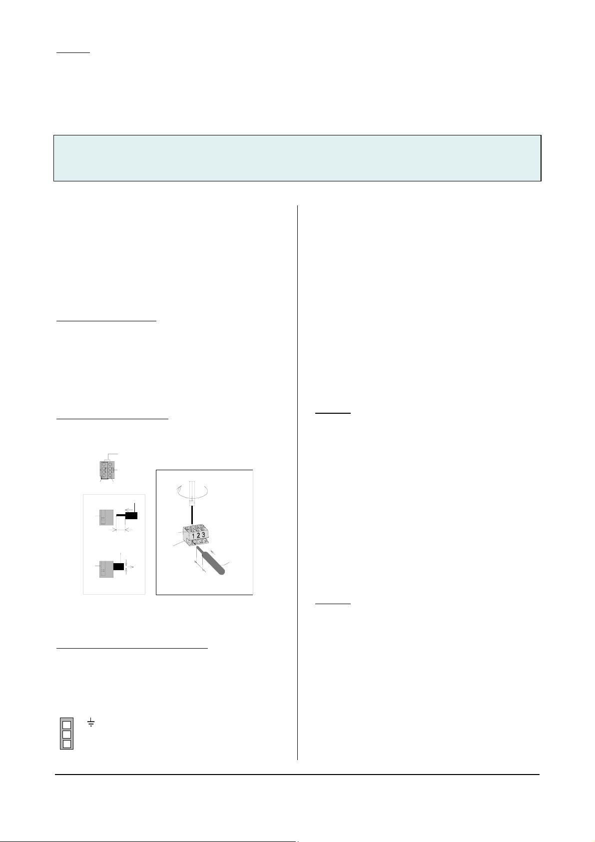
Diagram 1: drilling jig for cavity wall box for Touch
panel UP 588
VWARNING
•The device may only be installed and commissioned
by an authorised electrician.
•The device may only be used in connection with the
named accessories, in particular the flush-type box.
•230V devices which are not included with supply may
not be inserted in the flush-type box. It is also not
possible to loop through 230V cables.
•The prevailing safety and accident regulations should
be observed.
•The power supply voltage may only be connected to
the supply if the device has been fully installed.
•Electrical isolation should be ensured between the
bus cable and the 230V power supply.
•For planning and construction of electric installations,
the relevant guidelines, regulations and standards of
the respective country are to be considered.