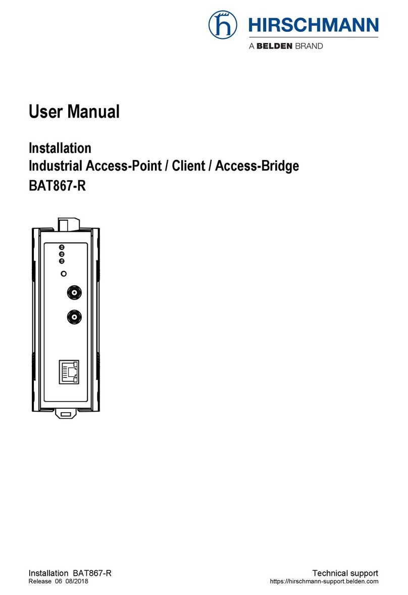
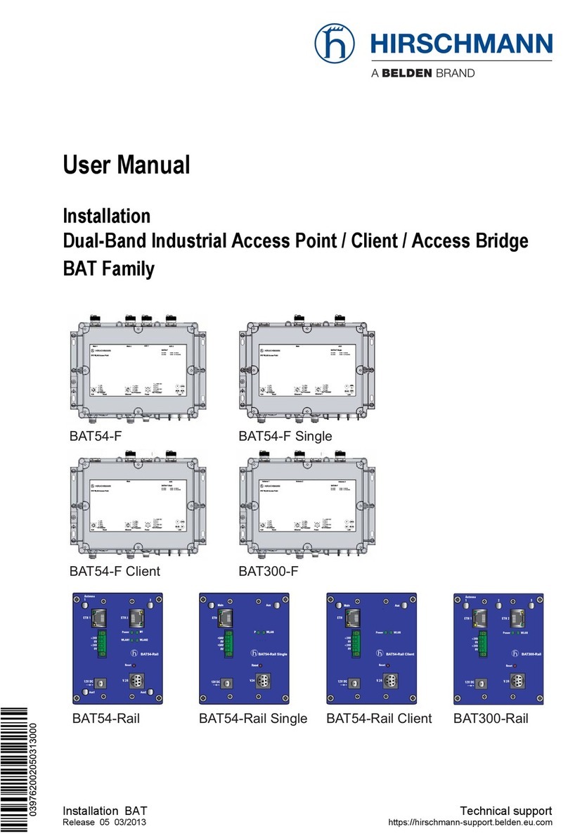
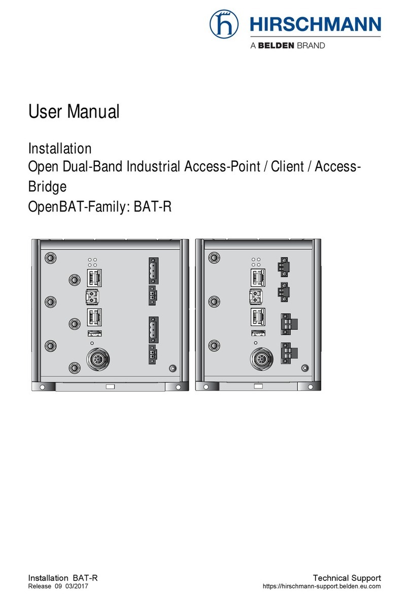
Hirschmann BAT54-F Series User manual

BAT54-F
Release
12/07
Technische Unterstützung
User Manual
Installation
Dual-Band Industrial Access Point /
Access Client / Access Bridge
BAT54-F Outdoor Series

The naming of copyrighted trademarks in this manual, even when not specially indicated, should
not be taken to mean that these names may be considered as free in the sense of the trademark
and tradename protection law and hence that they may be freely used by anyone.
© 2007 Hirschmann Automation and Control GmbH
Manuals and software are protected by copyright. All rights reserved. The copying, reproduction,
translation, conversion into any electronic medium or machine scannable form is not permitted,
either in whole or in part. An exception is the preparation of a backup copy of the software for
your own use. For devices with embedded software, the end-user license agreement on the en-
closed CD applies.
The performance features described here are binding only if they have been expressly guaran-
teed in the contract. This publication has been created by Hirschmann Automation and Control
GmbH according to the best of our knowledge. Hirschmann reserves the right to change the con-
tents of this manual without prior notice. Hirschmann can give no guarantee in respect of the
correctness or accuracy of the details in this publication.
Hirschmann can accept no responsibility for damages, resulting from the use of the network
components or the associated operating software. In addition, we refer to the conditions of use
specified in the license contract.
Printed in Germany
Hirschmann Automation and Control GmbH
Stuttgarter Str. 45-51
72654 Neckartenzlingen
Germany
Tel.: +49 1805 141538
039 706-001-01-1207 – 22.1.08

BAT54-F
Release
12/07 3
Contents
Safety instructions 4
About this manual 8
Legend 8
1 Device description 9
1.1 Properties and functions 9
1.2 Connections 11
1.4 External antennas 13
1.4.1 Transmission power 13
1.4.2 Omnidirectional antennas 15
1.4.3 Beam antennas 16
1.5 Cables and adapters 18
2 Assembly and start-up 20
2.1 Unpacking and checking 20
2.2 Installing the device 20
2.2.1 Setting up the device 21
2.2.2 Wall mounting 21
2.2.3 Mounting the device outdoors 21
2.2.4 Mounting/connecting external antennas 23
2.2.5 Connecting LAN and WLAN connections 24
2.2.6 Connecting the supply voltage 24
2.2.7 Grounding 25
2.2.8 Installing the data lines 26
2.2.9 Mounting the housing cover 28
2.3 Startup 29
2.4 Finding and configuring devices 29
2.5 Display elements 29
2.6 Operation element (reset button) 31
2.7 Making basic settings 33
3 Technical data 34

4BAT54-F
Release
12/07
Safety instructions
This documentation contains instructions which must be observed to ensure
your own personal safety and to avoid damage to devices and machinery.
Certified usage
The device may only be employed for the purposes described in the cat-
alog and technical description, and only in conjunction with external de-
vices and components recommended or approved by the manufacturer.
The product can only be operated correctly and safely if it is transported,
stored, installed and assembled properly and correctly. Furthermore, it
must be operated and serviced carefully.
Supply voltage
The devices are designed for operation with a safety extra-low voltage.
Accordingly, only PELV circuits or SELV circuits with voltage restrictions
in line with IEC/EN 60950 may be connected to the supply voltage con-
nections.
The supply voltage is electrically isolated from the housing.
Use only undamaged parts!
Relevant for North America:
The subject unit is to be supplied by a Class 2 power source complying
with the requirements of the National Electrical Code, table 11(b). If
power is redundant supplied (two individual power sources) the power
sources together should comply with the requirements of the Na-tional
Electrical Code, table 11 (b).
Relevant for North America:
Use 60/75°C or 75°C copper(CU)wire only.
Shielding ground
The shielding ground of the connectable twisted pair lines is connected to
the housing as a conductor.
Beware of possible short circuits when connecting a cable section with
conductive shielding braiding.
Housing
Only technicians authorized by Hirschmann are permitted to open the
housing.
A separate screw connection on the housing is provided for the function
ground. It is indicated by the function ground symbol. The function ground
is electrically connected to the switching ground and the metal housing of
the device.
Make sure that the electrical installation meets local or nationally ap-
plicable safety regulations.

BAT54-F
Release
12/07 5
Never insert pointed objects (thin screwdrivers, wires, etc.) into the in-
side of the subrack! Failure to observe this point may result in injuries
caused by electric shocks.
Environment
The device may only be operated at the specified maximum ambient tem-
perature and relative air humidity (non-condensing).
Install the device in a location where the climatic threshold values
specified in the technical data are adhered to.
Only to be used in an environment with the contamination level speci-
fied in the technical data.
When installing external antennas, make sure that you adhere to the
regulations of the country in which you are operating the WLAN de-
vice.
In ambient temperatures under -10 °C, use cabling designed for mini-
mum temperatures.
Relevant for use in Ex zone 2 according to ATEX 95 (ATEX 100a):
Only products labeled accordingly may be operated in Ex zone 2.
When operating the device in Ex zone 2, the following applies:
II 3G
Ex nA II T4 -20°C ... +60°C
KEMA 07 ATEX 0190
DO NOT OPEN THE DEVICE WHEN IT IS ELECTRICALLY CHARGED.
DO NOT DETACH ANY CONNECTORS WHEN THE DEVICE IS ELEC-
TRICALLY CHARGED.
DO NOT REMOVE THE LABELED HOUSING COVER.
The BAT54-F X2 (FCC) devices are installed with a housing cover - as
mounted in the state on delivery.
Qualification requirements for personnel
Qualified personnel as understood in this manual and the warning signs,
are persons who are familiar with the setup, assembly, startup, and oper-
ation of this product and are appropriately qualified for their job. This in-
cludes, for example, those persons who have been:
Xtrained or directed or authorized to switch on and off, to ground and to
label power circuits and devices or systems in accordance with current
safety engineering standards;
Temperature code T4 Ambient –20 °C … +60 °C
List of standards EN 60079-0: 2006
EN 60079-15: 2005
CLC/TR 50427: Dec. 2004

6BAT54-F
Release
12/07
Xtrained or directed in the care and use of appropriate safety equipment
in accordance with the current standards of safety engineering;
Xtrained in providing first aid.
General safety instructions
This device is electrically operated. Adhere strictly to the safety require-
ments relating to voltages applied to the device as described in the oper-
ating instructions!
Failure to observe the information given in the warnings could result in
serious injury and/or major damage.
Only personnel that have received appropriate training should operate
this device or work in its immediate vicinity. The personnel must be ful-
ly familiar with all of the warnings and maintenance measures in these
operating instructions.
Correct transport, storage, and assembly as well as careful operation
and maintenance are essential in ensuring safe and reliable operation
of this device.
Only use undamaged parts!
These products are only to be used in the manner indicated in this ver-
sion of the manual. Particular attention is to be paid to all warnings and
items of information relating to safety.
Any work that may have to be performed on the electrical installation
should be performed by fully qualified technicians only.
National and international safety regulations
Make sure that the electrical installation meets local or nationally ap-
plicable safety regulations.
When installing external antennas, make sure that you adhere to the
regulations of the country in which you are operating the WLAN de-
vice.
Note on the CE marking
The devices comply with the regulations contained in the following Euro-
pean directives:
2006/95/EG, 89/336/EWG
Directive of the council for standardizing the regulations of member states
on electromagnetic compatibility (changed by RL 91/263/EEC, 92/31/
EEC and 93/68/EEC).
1999/5/EG
Directive of the European Parliament and the council for radio installa-
tions and telecommunication systems and for the mutual recognition of
their conformity.

BAT54-F
Release
12/07 7
2006/95/EG
Directive of the European Parliament and the council for standardizing the
regulations of member states with regard to electrical equipment for use
within specific voltage limits.
In accordance with the above-named EU directives, the EU conformity
declaration will be at the disposal of the relevant authorities at the follow-
ing address:
Hirschmann Automation and Control GmbH
Stuttgarter Strasse 45-51
72654 Neckartenzlingen
Tel.: +49 1805 141538
The product can be used in living areas (living area, place of business,
small business) and in industrial areas.
Warning!
This is a class A device. This device can cause interference in living ar-
eas, and in this case the operator may be required to take appropriate
measures.
The assembly guidelines provided in these instructions must be strictly
adhered to in order to observe the EMC threshold values.
FCC note
Appropriate testing has established that this device fulfills the require-
ments of a class A digital device in line with part 15 of the FCC
regulations.
These requirements are designed to provide sufficient protection against
interference where the device is being used in a business environment.
The device creates and uses high frequencies and can radiate same, and
if it is not installed and used in accordance with this operating manual, it
can cause radio transmission interference. The use of this device in a
living area can also cause interference, and in this case the user is
obliged to cover the costs of removing the interference.
Recycling note
After usage, this product must be disposed of properly as electronic waste
in accordance with the current disposal regulations of your county / state
/ country.

8BAT54-F
Release
12/07
About this manual
The following manuals are available as PDF files on the CD-ROM supplied:
X"Installation" user manual
XReference Manual
Legend
The commendations used in this manual have the following meanings:
XListing
Work step
Subheading

BAT54-F
Release
12/07 9
1 Device description
1.1 Properties and functions
The BAT54-F enables you to set up WLANs (Wireless Local Area Networks)
in order to connect individual devices (PCs and mobile computers) with a lo-
cal network. In contrast to a conventional LAN, the communication here is by
means of radio links, not network cables.
The BAT54-F devices can be used for both new installations and for expand-
ing an existing LAN. Thanks to their high level of flexibility, you can combine
large, small, mobile and non-mobile locations. Anywhere that high band-
widths, stable operation and network security is required, wireless LAN with
the BAT54-F provides the ideal solution.
The BAT54-F is an access point/access client with a WLAN interface for du-
alband operation in accordance with IEEE802.11b/g and IEEE802.11a/h,
and it is specially designed for outdoor use with protection class IP67. The
BAT54-F can be installed quickly and easily using wizards via the Windows
configuration software or the Web interface. The wide range of BAT anten-
nas provide the correct solution for every requirement - even out-of-the-box
solutions.
The devices are designed for the special requirements of industrial automa-
tion. They are suitable for outdoor use and in environments with the danger
of explosions. They meet the relevant industry standards, provide very high
operational reliability, even under extreme conditions, and also long-term re-
liability and flexibility. The devices operate without fans and have a redun-
dant voltage supply. You can mount the devices on a wall or a pole.
It can be easily managed via a Web browser, via Telnet, with a management
software product (such as HiVision) or locally on the device (V.24 interface).
The devices differ with regard to their certification and the type of integrated
intenna (if included).
The devices provide you with a large range of features:
XSturdy metal housing with protection class IP67
XSecure wall and pole mounting
XRedundant power supply with two 24V supplies and one Power over ETH-
ERNET supply
XTemperature range –20° to +55°C
XWireless LAN interfaces in accordance with IEEE802.11b/g and
IEEE802.11a/h
XCreation of redundant WLAN connections for secure data transmission

10 BAT54-F
Release
12/07
XTransmission with up to 108 MBit/s for each radio module
XAlso maximum security for point-to-point with IEEE802.11i
XRS-232 serial interface for configuration and remote access
XBoth radio modules can be operated separately as an access point or ac-
cess client
XHigh mobility combined with maximum security
XFaster roaming and prioritizing, also with 802.1x authentication
XHigh performance operating system with high range of functions via Mul-
tiSSID, VLAN, Rapid SpanningTree, RADIUS server, IP router, firewall,
DHCP server, etc.
XManagement software for Windows, Web configuration, Telnet interface
and management via SNMP
Antenna technology for a high quality signal
XFor operation indoors and outdoors
XMounting with cables provided
XSecure wall and pole bracket
XOptimized distribution and performance for every application
XLong transmission distances
XDesigned for 2.4 GHz and 5 GHz wave bands
Cross-platform WLAN management
XA standardized, cross-platform management system for transparent
and efficient network monitoring
XWindows management suite: LANconfig, LANmonitor, WLANmonitor
XDirect management via Web browser (HTTP, HTTPS)
XCommand line level: TelNet
XCan always be reached via serial interface
XPartial configuration of multiple devices via scripting
XWLANmonitor for convenient monitoring of WLANs with Rogue AP
Detection
XMonitoring of all BAT54-F devices as clients and as access points in
an application
Communication via all levels
The addition, to the BAT wireless transmission system, of the RS20/
RS30/RS40 open rail range of switches, the MICE range of switches, the
MACH range of backbone switches, the EAGLE security system, and
products for the LION control room, provides continuous communication
across all levels of the company.

BAT54-F
Release
12/07 11
1.2 Connections
The devices are equipped with the following connections and operation ele-
ments:
XMain1: Main connection for the first WLAN module
for connecting external antennas
XMain2: Main connection for the second WLAN module
for connecting external antennas
XAUX1: Auxiliary connection for the first WLAN module
for connecting external antennas
XAUX2: Auxiliary connection for the second WLAN module
for connecting external antennas
XV.24: Serial interface, 4-pin M12 socket with A coding,
data rate min. 19.2 kbit/s, max. 115 kbit/s,
for connecting serial configuration cable
XEthernet port: 4-pin M12 socket with D coding
10/100BASE-TX, Autosensing, Power over Ethernet (PoE), automatic
MDI/MDIX recognition (no crossover cable required)
XPower: Power supply connection for safety extra-low voltage (SELF/
PELV), 5-pin M12 plug
XReset button: Restarts device or resets the configuration
Main1 Main2 AUX1 AUX2
V.24
Reset
Ethernet
Power
LEDs

12 BAT54-F
Release
12/07
1.3 Device models
Figure 1: Device models BAT54-F, BAT54-F FCC
Figure 2: Device models with housing cover: BAT54-F X2, BAT54-F X2 FCC
Device Area of application
BAT54-F FCC Under extreme conditions
BAT54-F Under extreme conditions
BAT54-F X2 FCC Under extreme conditions, including environments with the danger of ex-
plosions
BAT54-F X2 Under extreme conditions, including environments with the danger of ex-
plosions

BAT54-F
Release
12/07 13
1.4 External antennas
External antennas are required to operate the access point.
You will find an overview of the antennas that are supported and can be con-
nected, along with the technical data, on the Hirschmann website under
www.hirschmann-ac.com.
When installing external antennas, make sure that you adhere to the reg-
ulations of the country in which you are operating the WLAN device.
1.4.1 Transmission power
The operator of a WLAN radio installation must ensure that the transmission
threshold values are adhered to.
Hirschmann provides support in adhering to the transmission power thresh-
old values.
Use LANconfig to start the configuration of the device. (This program is
located on the CD provided.)
Go to the settings for "Wireless LAN".
There you enter the country in which you are installing the device (see the
following figure).
Then you open the configuration for the physical interface to which you
are connecting the antenna. On the "Radio" tab you will find an entry field
for the "antenna gain" (see the following figure).

14 BAT54-F
Release
12/07
Here you enter the value listed for your antenna in the following table.
Antenna designation Frequency range Entry under "Antenna
gain" in dBi
BAT-ANT-N-8G 2.4 GHz 8
BAT-ANT-N-8A 5 GHz 8
BAT-ANT-N-6ABG 2.4 GHz 6
5 GHz 8
BAT-ANT-TNC-B-D-085-01 2.4 GHz 9
BAT-ANT-TNC-B-D-085-02 2.4 GHz 9
BAT- ANT- TNC- 8B/G DS 2.4 GHz 9
BAT- ANT- TNC- 10 A DS 5 GHz 10
BAT- ANT- N-14G 2.4 GHz 14
BAT-ANT-N-12A 5 GHz 12
BAT- ANT- N – 23/9 A 5 GHz 23

BAT54-F
Release
12/07 15
When the antenna gain is set correctly, the power emitted from the antenna
is reduced so that the overall system adheres to the EIRP threshold values
(transmission power output of the antenna).
The following frequency ranges, tranmission modes and maximum transmis-
sion powers are permitted in Japan:
Allowed channels for 2.4 GHz non-turbo operation
Channel(s) 1(2412 MHz), 2(2417 MHz), 3(2422 MHz), 4(2427 MHz),
5(2432 MHz), 6(2437 MHz), 7(2442 MHz), 8(2447 MHz), 9(2452 MHz),
10(2457 MHz), 11(2462 MHz), 12(2467 MHz), 13(2472 MHz),
14(2484 MHz):
XEIRP limit 18 dBm
XBoth indoor and outdoor usage
Allowed channels for 2.4 GHz turbo operation
Channel(s) 6(2437 MHz):
XEIRP limit 20 dBm
XBoth indoor and outdoor usage
Channel(s) 14(2484 MHz):
XEIRP limit 20 dBm
XBoth indoor and outdoor usage
Allowed channels for 5 GHz non-turbo operation
Channel(s) 36(5180 MHz), 40(5200 MHz), 44(5220 MHz), 48(5240 MHz):
XEIRP limit 23 dBm
XIndoor only usage
Allowed channels for 5 GHz turbo operation
(Nothing allowed)
1.4.2 Omnidirectional antennas
The following antennas are available for 2.4 and 5 GHz:
XBAT-ANT-8G (2.4 GHz) or BAT-ANT-8A (5 GHz)
Antennas with omnidirectional characteristics for use in halls or open spaces.
BAT-ANT-8A BAT-ANT-8G

16 BAT54-F
Release
12/07
XBAT-ANT-N-6ABG (2.4 / 5 GHz)
Omnidirectional antenna (hemispherical antenna) for use in both frequency
ranges. In industrial environments, this is the preferred choice for use on mo-
bile devices or switch cabinets. It is water resistant and sealed in accordance
with protection class IP67.
1.4.3 Beam antennas
The following antennas are available for 2.4 and 5 GHz:
XBAT-ANT-TNC-B-D-085-01 (circular, 2.4 GHz)
Circular polarized sector antenna. Reduces packet losses caused by faults,
reflection or interference.
XBAT-ANT-TNC-B-D-085-02 (linear, 2.4 GHz)
Sector antenna for 2.4 GHz indoors and outdoors.
BAT-ANT-N-6ABG
BAT-ANT-TNC-B-D-085-01

BAT54-F
Release
12/07 17
XBAT-ANT-N-12A (linear, 5 GHz)
Sector antenna for 5 GHz band indoors and outdoors.
XBAT-ANT-TNC-8b/g DS (linear, 2.4 GHz) or
BAT-ANT-TNC-10 A DS (linear, 5 GHz)
Sector antennas with polarization diversity. Reduction in packet losses
through use of vertical and horizontal polarization. Supported by the diversity
antenna connections of the BAT54-F. Select the "Use best antenna for trans-
mission" setting in the WLAN interface setting.
BAT-ANT-TNC-B-D-085-02
BAT-ANT-N-12A
BAT-ANT-TNC-10 A DSBAT-ANT-TNC-8b/g DS

18 BAT54-F
Release
12/07
XBAT-ANT-N-23/9 A (linear, 5 GHz) or
BAT- ANT- N-14G (linear, 2.4 GHz)
Strongly directed antenna for bridging large distances in the open. Ideal for
point-to-point connections.
1.5 Cables and adapters
BAT-ANT-N-23/9 A BAT-ANT-N-14G
BAT-CLB-7-TNC
Low loss cable ULA400
BAT-CLB-7-N
Low loss cable ULA400
BAT-Pigtail
BAT Surge Arrestor

BAT54-F
Release
12/07 19
Cables
XBAT-CLB-7-N
Antenna cable 7 m, N plug to N plug, ULA400,
attenuation 2 dB at 2.4 GHz, 3 dB at 5 GHz
XBAT-CLB-7-TNC
Antenna cable 7 m, N plug to TNC plug, ULA400,
attenuation 2 dB at 2.4 GHz, 3 dB at 5 GHz
Adapters
XBAT-Pigtail
Adapter from RP-SMA plug to N socket,
attenuation 0.5 dB at 2.4 GHz, 3 dB at 5 GHz
XBAT Surge Arrestor
Lightening protection adapter, N socket to N socket

20 BAT54-F
Release
12/07
2 Assembly and start-up
The devices have been developed for practical application in a harsh indus-
trial environment. The installation process is correspondingly simple.
On delivery, the device is ready for operation.
The following procedure has been proven to be successful for the assembly
of the device:
XUnpacking and checking
XSetting up the device
XWall mounting
XPole mounting
XMounting/connecting external antennas
XConnecting LAN and WLAN connections
XConnecting the supply voltage
XGrounding
XInstalling the data lines
XMounting the housing cover
XStartup
XFinding and configuring devices
2.1 Unpacking and checking
Check whether the contents of the package are complete (see page 36
"Scope of delivery").
Check the individual parts for transport damage.
2.2 Installing the device
To protect the exposed contacts of the components still to be installed from
dirt, the individual system components must be connected in a dry and clean
area. Seal unused ports with the cover caps supplied.
Note: Connectors are not electrical isolating devices.
Therefore, first plug the connector into the power supply plug and then switch
on the power supply.
Note: Protection class IP67 is only achieved if all the connected components
also fulfill protection class IP67.
This manual suits for next models
4
Table of contents
Other Hirschmann Wireless Access Point manuals
Hirschmann
Hirschmann BAT54-Rail User manual
Hirschmann
Hirschmann NetModule AP3400 User manual
Hirschmann
Hirschmann BAT-C2 User manual
Hirschmann
Hirschmann BAT54 User manual

Hirschmann
Hirschmann BAT54-Rail User manual
Hirschmann
Hirschmann BAT-F User manual
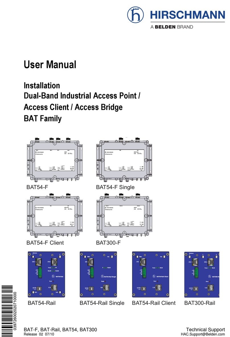
Hirschmann
Hirschmann BAT54-F User manual
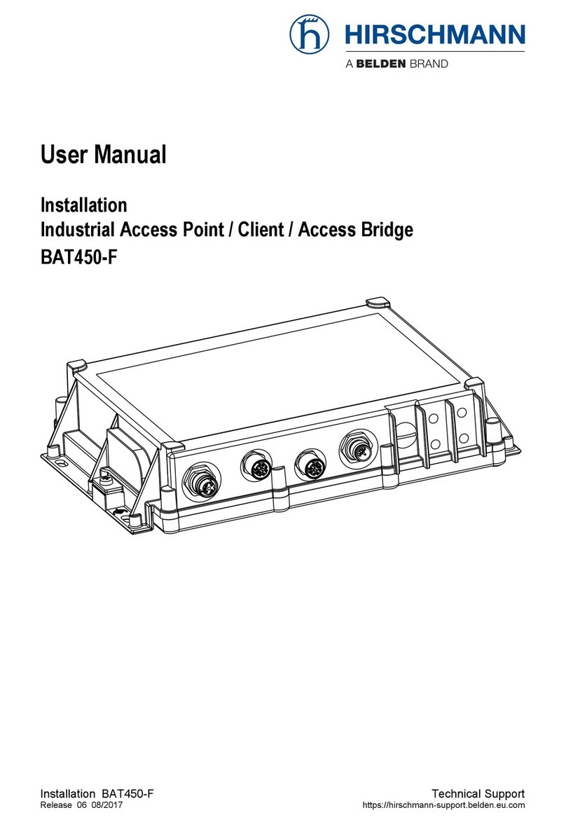
Hirschmann
Hirschmann BAT450-F User manual

Hirschmann
Hirschmann BAT 11b User manual

Hirschmann
Hirschmann BAT450-F User manual
