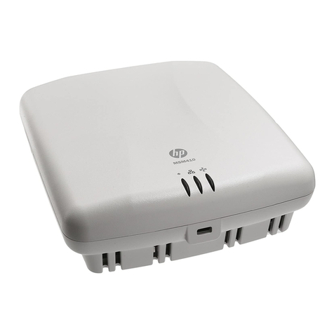
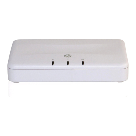
HP ProCurve MSM317 Quick reference guide

HP MSM317 Access Device
Deployment guide
Technical white paper
Table of contents
Introducing the MSM317...................................................................................................................... 2
MSM317 versus traditional access points ............................................................................................... 4
Installation considerations..................................................................................................................... 7
Radio frequency properties of the MSM317........................................................................................ 7
Location planning............................................................................................................................. 8
Checking radio coverage................................................................................................................ 12
Adjusting power output and data rates ............................................................................................. 12
Power over Ethernet ........................................................................................................................... 13
Uses of the pass-through port .............................................................................................................. 14
Switch functionality on the MSM317.................................................................................................... 14
Deploying Voice over IP ..................................................................................................................... 15
VLAN configuration on non-LLDP-MED capable devices ...................................................................... 15
Deploying IP phones—LLDP-MED devices .......................................................................................... 16
Authentication ............................................................................................................................... 17
Configuring per-room guest VLANs ...................................................................................................... 18
VoIP/LLPD-MED use cases................................................................................................................... 19

2
Introducing the MSM317
Over the last five years, the expectations of hotel guests for wireless connectivity have changed
dramatically. Earlier wireless deployments consisted of hotspot services in public areas such as
lobbies and food service locations. Today, wireless connectivity in guest rooms has become pervasive
in almost all brand segments. In the lucrative business and luxury markets, guests are highly valued for
their loyalty as it often leads to repeat and referral business. Consequently, pressure to meet the
wireless demands of guests for consistent, high-performance connections that support all of their Wi-Fi
devices—just like at home or in the office—is extremely high.
These expectations expose shortcomings in traditional approaches to deploying guest networks in
hospitality settings. Provisioning a traditional access point (AP) to provide coverage to multiple rooms
creates an inconsistent guest experience for two key reasons. First, the performance of an individual
connection decreases the farther away it is from the AP. Second, performance for all users is
compromised by the presence of low data rate connections, which causes degradation throughout the
system due to the sharing of the wireless medium. The proliferation of wireless devices, such as
smartphones and smartbooks adds pressure to network capacity, further eroding performance.
Figure 1: A wide variety of devices can be connected to the MSM317. You can configure the network to send traffic through
the MSM7xx Controller or, in cases where private access areas are isolated from public spaces, you can bypass the controller
completely. Where VoIP phones are deployed, for example, this avoids an additional hop that can slow service.
The MSM317 is an integrated switch/wireless AP designed from the ground up for high-density
environments. This discrete device enables an optimal Internet access experience and more. The same
device supports the delivery of other applications demanded by guests and occupants today—IPTV,
VoIP, and other IP-based services—while paving the way for future services that can further enhance
the end-user experience.

3
Requiring only a single Power over Ethernet (PoE) cable drop to support voice, video, and data, the
MSM317 simplifies installation and decreases expensive site surveys required with traditional APs. Its
four-port switch and AP are centrally managed through the HP MSM7xx Controller. This means faster
configuration of multiple devices, automated software updates, and the delivery of a consistent set of
services throughout the network. In short, the MSM317 revolutionizes the deployment of converged
environments, all at a reduced cost of ownership.
Note:
This guide assumes the use of version 5.5 software on the MSM317 and
MSM7xx Controller. If you are using an older version, it is recommended
that you upgrade immediately.
Features and benefits of the MSM317
The MSM317 is purpose-built for cost-effective, high-density deployments focused on quality of experience. Key
features include:
•Converged wired/wireless solution
•Dedicated service per room
•Simplified installation—single cable for voice, video, and data
•Mounts in standard electrical wall box
•802.11 b/g access point
•4-Port, 10/100 managed switch
•Powered by 802.3af or 802.3at PoE
•Single PoE port
•Centralized configuration and management through MSM7xx Controller*
•LLDP-MED for automatic IP phone configuration at switch port
•Quality of Service (QoS) and rate limiting for delivery of latency-sensitive applications
•Loop protection at switch ports
•Pass-through RJ-45 connection for support of legacy devices
•Bulk moving of devices between groups using controller interface
Note:
* The MSM317 is a controlled-mode only device. Use of an HP MSM7xx
Controller is required to configure it.

4
MSM317 versus traditional access points
The MSM317 offers several features that distinguish it from a standard access point and make it the
right choice for high-density deployments. The table below provides a side-by-side comparison of the
MSM317 and the HP E-MSM310 AP.
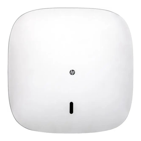
Feature MSM317 MSM310
Connectivity Dedicated wireless connectivity per room.
Excellent choice for high-density deployments
where high-quality guest experience is
top priority.
Shared bandwidth across many users. Correct
choice for public spaces such as conference
rooms, lobbies, restaurants, and outdoor areas.
Coverage area Designed for a small space of up to
430 square feet (40 square meters).
Designed for medium to large spaces of up to
10,000 square feet (930 square meters).
Output power 802.11g–14.5 dBm (28 mW) or
802.11b–6 dBm (39 mW) maximum. Ideally
suited for high throughput with the fewest
errors and least amount of interference
between APs.
Approximately 20 dBm (100 mW). Higher
output power delivers adequate coverage to
large spaces.
Antenna Two internal omnidirectional antenna chips
with separate horizontal and
vertical polarities.
Two, 2 dBi dual-band 2.4/5 GHz
omnidirectional antennas for 360 degree
horizontal radiation pattern.
Power 802.3af PoE and 802.3at PoE+. Less
cabling, cheaper than AC power, reduced
carbon footprint, and fits into standard
electrical wall boxes.
802.3af PoE or 5 VDC from available AC power
supply. May require new wiring to add
access points.
Switching Integrated 4-port, 10/100 Ethernet switch for
delivery of voice, video, and data services.
None.
5
Figure 2:Traditional APs transmit at a higher output power than the MSM317 in order to provide coverage to a large area.
Multiple users need to share bandwidth.
Figure 3:Designed with small spaces in mind, the MSM317 helps to reduce interference with other APs.

6
In a typical hotel configuration, the AP resides in a corridor and provides shared bandwidth to
multiple rooms. This set up generally works well for a limited pool of users. As network load
increases, however, performance is likely to degrade, especially during peak usage periods.
One solution is to boost the AP’s output power to extend its reach, however, this presents several
potential pitfalls. First, clients at the periphery may not have enough power to reach the AP.
Second, there is the matter of fairness to users. Those on the periphery may experience lower
throughput, while those closer to the AP may see a lack of responsiveness. Third, the risk of
interference and transmission errors increases at higher power levels. Another option is to add APs,
but this would require paying for new wiring and site surveys and does not address delivery of
IP-enabled services.
In contrast to a standard AP, the MSM317 delivers dedicated, predictable coverage per room,
providing distinct advantages over conventional deployments. Benefits include a dedicated wireless
connection per user and reduced risk of signal interference due to the unit’s radiation pattern and
lower output power. Scaling up is also easier and more affordable as the MSM317 fits into a
standard electrical wall box and requires only a single PoE cable drop. Finally, its built-in Ethernet
switch delivers voice, video, and data services, while the pass-through port allows for the integration
of legacy devices.
Note:
Roaming is supported between traditional APs and the MSM317.
Figure 4:Output power to data rate ratio of the MSM317 compared to a full-power AP.
0
5
10
15
20
25
6 9 12 18 24 36 48 54
Output power (±1.5dBm)
Data rate (Mbps)
MSM317
MSM310

7
Installation considerations
Proper planning and configuration of the MSM317 are critical for providing high-quality wireless
service. This section provides an overview of the radio frequency properties of the MSM317,
considerations for setting output power and data rates, and guidelines for where to install the unit.
Radio frequency properties of the MSM317
The MSM317 features a built-in 802.11 b/g radio with two integrated 2.4 GHz omnidirectional
antennas. This helps to produce the strongest possible signal and reduce leakage between rooms. The
signal propagates away from the wall on which the unit is mounted, resulting in reduced radiation
from the back of the device and less risk of interference with the adjacent room.
Figure 5:Comparison of actual throughput between an 802.11n and 802.11g 1x1 device.
Comparing 1x1 wall
jack solutions
When comparing wall jack
solutions that support one
spatial stream (1x1
configuration), 802.11n
enabled devices can deliver
higher throughput, but there
are limitations in the
implementation of the
standard. This is due to the
RTS/CTS overhead that
occurs when servicing
legacy clients, which
prevents a 1x1 device from
using a 40 MHz channel.
The throughput comparison
chart shows in real-world
terms the difference in
performance between a 1x1
b/g and an 11n wall jack
solution. As the chart shows,
the difference in data rates
between the two is small
and becomes even less
significant when you factor
in RTS/CTS overhead.

8
Figure 6:The MSM317 provides 120 degrees or greater signal coverage on the horizontal plane and a vertical signal that is
narrower than that of a traditional AP.
Location planning
Care should be taken to install the MSM317 in a location where there are as few obstructions as
possible to the signal. It is recommended that you mount the unit in an exposed area, such as under a
desk (without a courtesy panel) or on a wall. You may also consider mounting it in a hollow hidden at
the back of a wood desk (however, there may be some signal attenuation depending on the density
of the wood). In addition, be sure to install the unit with its faceplate as this helps to keep the antenna
external and maintain airflow around the device.
Before deployment, closely consider your environment, including building materials, building design,
and equipment. Metal, which may be contained in walls, windows, or equipment, is likely to block or
diminish the signal.
In addition, if you deploy the MSM317 in certain places, such as behind a minibar or wall, expect to
see significant variation from ideal conditions. Glass and wood, on the other hand, generally have
less impact on signal strength.

9
Figure 7:The faceplate of the MSM317 helps to prevent the antenna from being blocked behind a wall or enclosure and keep
the unit from overheating. The trim panel is vented to allow airflow..
The following figures are WLAN coverage maps created using HP RF Planner software for two
different room types. These maps reveal available signal strength in dBm at various points in
the rooms.
Figure 8 shows an actual configuration of two typical rooms in a luxury hotel. The map is overlaid
with the anticipated RF coverage pattern, and an MSM317 is deployed in each room (A).
The area of each room is 34 square meters (that is, within the 40 square meter guideline for
successful deployment).
The signal strength in the sleeping and living areas (B) is excellent, as is the delineation of coverage
between the rooms. Signal strength at the periphery of the coverage area, and in particular in the
bathrooms (C), has diminished to the point that higher-speed connections would be difficult
to maintain.
The primary contributor to signal degradation in the bathroom is room construction, as the interior of
the room is lined with granite tiles. The coverage characteristics could easily have been improved by
moving the MSM317 to a more central position on the same wall. In this case, however, room décor
and colocation with other in-room services was traded off against improved coverage in the
bathroom, and deployment was continued at the planned location.

10
Figure 8:WLAN coverage map for two typical rooms in a luxury hotel.
Figure 9 shows a room from the same property in a suite configuration. The room is 110 square
meters (more than twice the recommended size). Based on deployment of the MSM317 (A), coverage
in the sleeping and living area (B) is excellent. The bathroom (C), which features granite tiles, has
useable coverage due to its proximity to the MSM317 (although the tiling impacts coverage in the
area adjacent to the bathroom). Coverage in the sitting and kitchen area (D) is inconsistent, ranging
between good to nonexistent. This can be attributed to the reinforced concrete wall separating the
room’s two main areas. Given the room’s size and construction, the coverage pattern of the MSM317
is expected. Solutions for improving coverage in these high-value rooms include:
•Deploying a second MSM317
•Using a standard AP in the room as an alternative to multiple MSM317s
•Filling in the coverage gaps for multiple rooms by installing a standard AP in the corridor
A
B
C
C
A
B

11
In this real-world example, the second option was chosen as the one that would provide an excellent
balance of coverage and cost, and deliver an acceptable experience to the hotel guest.
Figure 9:WLAN coverage map for a suite in a luxury hotel.
B
A
D
C

12
Checking radio coverage
It is recommended that you confirm deployment by observing radio coverage on a sampling of typical
rooms. Before doing so, check the rooms to make sure that the MSM317 units have been installed
according to the “Installation considerations” section above. If they have, the default power and data
rate settings should be adequate.
Ultimately, user experience is the most important factor in evaluating the quality of a wireless
connection. To check Wi-Fi coverage, use a laptop to run a wired speed check using a website such
as Speedtest.net. Follow this with a wireless speed check from various parts of the room (as an
alternative, you can navigate to a place where a user might typically go, such as a hotel splash
page). Wireless performance should be at least 25 percent of wired performance.
Note:
If the MSM317 is installed in rooms that vary from the typical layouts, you
should check radio coverage in those rooms too.
Adjusting power output and data rates
Although the MSM317 allows you to adjust power and data rates through the controller interface, it is
usually not necessary. Below are some points to consider before changing either setting:
•Is throughput at higher data rates within the terms of the service level agreement (SLA)? Check your
SLA requirements before making adjustments. What data rates does the agreement specify?
Does throughput satisfy those requirements?
•How would the commissioning and support model change? Would changes negatively impact these
parameters by increasing interference and making client associations less predictable?
Before reducing power or restricting data rates, be aware of the following:
•Reducing power may decrease co-channel interference but might also shrink the usable area of the
room. Remember too that the MSM317 already uses reduced power as compared to a typical AP.
•Disabling the lower data rates can help to facilitate the client in connecting to the correct MSM317
(that is, the one in the same room) rather than to one in an adjacent room. However, be aware that
disabling certain data rates may cause some clients to be unable to associate (although this
is uncommon).
If you find that you still want to make modifications, it is recommended that you wait until completing
and testing the initial deployment.
Note:
For instructions on changing data rates on the MSM317, see the
HP MSM7xx Controllers Management and Configuration Guide, the
chapter on working with VSCs. For instructions on changing output power,
see the same guide, the chapter on wireless configuration.

13
Power over Ethernet
Power over Ethernet has many advantages over AC wiring for powering IP phones and other devices.
It is cheaper, has a smaller carbon footprint than AC, and is not subject to the same code compliance
as AC installations. PoE devices also do not require standard power outlets, helping to contain the
cost of large deployments.
The MSM317 receives PoE power through its uplink port (either via the RJ-45 connector or
punch-down block). The uplink port must be connected to an 802.3af or 802.3at compliant power
source. The Ethernet connection to this port must be a standard 10/100 link delivered over
Category 5 (or better) structured cabling.
The MSM317 can supply PoE power on port 1. The power supply capability of port 1 is directly
related to the PoE source that powers it. The MSM317 requires about 6 watts for its own operation,
with the remaining power available to the port on the front of the unit.
Figure 10:External interfaces of the MSM317.
Before plugging a PoE device into this port, it is important to understand the device’s power
requirements as these dictate the PoE source type you need. For example, the Avaya 9640G/9620
IP phone is a Class 2 device, requiring a standard PoE source. Two PoE power settings are available
on port 1 of the MSM317:
•If the MSM317 is powered from an 802.3af standard PoE source, then port 1 can support Class 1
(3.84 watts) or Class 2 (6.49 watts).
•If the MSM317 is powered from an 802.3at PoE+ source with an output power greater than
23 watts, or a PoE injector capable of delivering greater than 15.4 watts (as specified in the
802.3af standard), then port 1 can support Class 0 (15.4 watts) and Class 3 devices (15.4 watts).
Note:
For more information on PoE and PoE+ on the MSM317, see the
HP MSM317 Access Device Installation and Getting Started Guide.

14
Choosing a PoE or PoE+ switch
HP offers a number of PoE and PoE+ enterprise-class switches for hospitality customers building
converged edge networks. The following are two such offerings.
E2610-48 PoE 2910-48G PoE+ al
Cost-effective, scalable, access layer switch High-performance Gigabit Ethernet access switch
IEEE 802.3af functionality IEEE 802.3af/802.3at functionality
48, 10/100 ports 48, 10/100/1000 ports
Two 10/100/1000 Base-T ports Four dual-personality ports for 10/100/1000 or
mini-GBIC connectivity
Two mini-GBIC slots for Gigabit Ethernet uplink connectivity Four optional 10 Gigabit Ethernet (CX4 and/or SFP+)
uplink ports
Layer 2 plus static IP routing Layer 2 and Layer 3 plus static IP and RIP routing
Lifetime warranty, free software updates, optional
redundant external power supply Lifetime warranty, sFlow, ACLs, rate limiting
Uses of the pass-through port
As mentioned, the pass-through port on the MSM317 is intended for use as a PBX pass through. If it is
used for any other purpose, it is rated for Category 3 connections. Use of this port in applications
requiring Category 5 or greater cabling is likely to impact the performance of that connection.
Switch functionality on the MSM317
The functionality of the switch on the MSM317 is broadly equivalent to a Layer 2 managed switch
typically deployed at the edge of an enterprise network. Configuration of the switch features have
been optimized for applications in the hospitality market. The sections that follow discuss configuring
VoIP and guest access VLANs on the MSM317.
Note:
For more information about switch functionality and configuration, see the
HP MSM317 Access Device Installation and Getting Started Guide,
configuration chapter.

15
Deploying Voice over IP
The following sections offer guidelines for deploying VoIP telephones with the MSM317. These
sections cover IP phones requiring manual VLAN configuration, as well as those that support Link
Layer Discovery Protocol Media Endpoint Discovery (LLDP-MED).
VLAN configuration on non-LLDP-MED capable devices
The MSM7xx Controller interface allows you to specify a primary VLAN to which you can designate
tagged or untagged network traffic, depending on the types of VoIP phones you plan to
deploy. Some phones are dual-stage; that is, the initial communication is untagged. Following receipt
of vendor-specific DHCP options to set voice VLAN, QoS, and DSCP, the phone switches to sending
tagged traffic for voice prioritization. In most VoIP Installations, the primary VLAN may remain at its
default untagged setting, and the secondary VLAN may designate the tagged VLAN to be used for
voice communications.
The MSM7xx Controller interface allows you to configure a primary VLAN to handle upstream
untagged IP phone traffic sent to the configuration server and a secondary VLAN to carry tagged
traffic once configuration is complete.
Figure 11:The MSM7xx Controller interface lets you specify a primary and secondary VLAN to handle upstream untagged IP
phone traffic as well as tagged traffic once the phone has received its configuration settings. The Quarantine VLAN and allow
dynamic VLAN assignment checkboxes apply to installations where the VoIP phone is authenticated with either 802.1X or
MAC authentication.
Note:
For more information on configuring VLANs for non-LLDP-MED capable
devices, see the HP MSM317 Access Device Installation and Getting
Started Guide, configuration chapter.

16
Deploying IP phones—LLDP-MED devices
IEEE 802.1AB LLDP provides a standards-based method for network devices to discover each other
and exchange information about their functionality. The MSM7xx Controller and MSM317 support
LLDP-MED, which extends the LLDP standard to support advanced features on the network edge for
VoIP endpoint devices with LLDP-MED capabilities. The extensions to LLDP include the specification of
additional TLV (Type, Length, and Value) entries for VoIP management.
LLDP-MED capable VoIP phones do not require manual VLAN tagging. Instead, the phones receive
their voice VLAN, QoS, and DSCP settings from the MSM317 through a network policy TLV and can
immediately begin communication using tagged traffic. For example deployments of LLDP-MED
capable IP phones with the MSM317, see the “VoIP/LLPD-MED Use Cases” section at the end of
this guide.
Figure 12:The MSM7xx Controller lets you define voice TLV settings and enables a Network Policy TLV for voice traffic on the
port. If you plan to use the same voice VLAN across a group of MSM317s, you can enable the TLV at the group level.
Note:
For more information on deploying LLPD-MED IP devices, see the
HP MSM7xx Controllers Management and Configuration Guide, LLDP
chapter, and the HP MSM317 Access Device Installation and Getting
Started Guide, configuration chapter.

17
Authentication
The MSM7xx provides three methods for authorizing IP phones on the MSM317: 802.1X
authentication, MAC address filtering, and MAC authentication. Configuring MAC filtering is the least
complex of these methods and is therefore recommended on the MSM317.
MAC address filtering lets you control port access based on client station MAC addresses. On the
MSM317, authorization is handled by the unit itself, and settings are defined on a per-port basis. Lists
of addresses that are permitted to transmit and receive are set at the port level. For each list, you
assign a global name that helps you identify it.
The controller allows you to apply various masks to a given list so that you can filter on a single
address, a range of addresses, or a group of devices, such as those from a certain vendor. Once you
have created your lists, you can specify which lists are allowed to access the port.
Authorizing IP end devices adds security to VoIP deployments but requires careful coordination of
installation and configuration to avoid problems. For example, if you configure MAC address filtering
on an MSM317 switch port and then attempt to install end devices prior to setting up the MAC
address list, the phones cannot pass traffic. It is recommended that you deploy the phones first and
then enable MAC address filtering.
Figure 13:To configure MAC filtering, use the controller to create lists of MAC addresses permitted to send and receive traffic
on an MSM317 switch port. You then specify these lists in the MAC filter area of the port configuration page for the port you
want to configure.
Note:
For instructions on configuring 802.1X authentication, MAC address
filtering, and MAC authentication on an MSM317 switch port, see the
HP MSM317 Access Device Installation and Getting Started Guide, the
section on configuring the switch ports. Also see the HP MSM7xx
Controllers Management and Configuration Guide, the chapter on user
authentication, accounts, and addressing.

18
Configuring per-room guest VLANs
The controller interface provides a port-to-port inheritance feature that lets you toggle inheritance at
the port level. This allows you to specify whether a port should inherit its configuration from the group
level, or whether it will need to use settings specific to the port. The port-to-port inheritance feature
eases the task of creating individual guest network VLAN access for hundreds of guest rooms.
Figure 14:The MSM7xx Controller interface offers a port-to-port inheritance feature that lets you specify whether a port will
inherit its configuration from the group level or operate according to its own configuration settings.
Note:
For instructions on configuring port-to-port inheritance, see the HP MSM317
Access Device Installation and Getting Started Guide, the section on
configuring the switch ports.

19
VoIP/LLPD-MED use cases
The following use cases show various ways that LLPD-MED capable IP phones can be deployed with
the MSM317. The first scenario (Figure 15) shows a configuration with LLPD-MED phones and no
authentication, the second (Figure 16) with LLPD-MED and 802.1X authentication, and the third
(Figure 17) with LLPD-MED and MAC authentication. In all scenarios, the MSM317 provides VLAN
access to the VoIP phones by using a primary untagged VLAN and secondary tagged VLAN.
Figure 15: In the diagram, the MSM317 provisions LLPD-MED, which automatically supplies VLAN, DSCP, and QoS.

20
Figure 16:In the diagram, the MSM317 provisions LLPD-MED, which automatically supplies VLAN, DSCP, QoS, and
802.1X authentication.
Other manuals for ProCurve MSM317
3
Table of contents
Other HP Wireless Access Point manuals