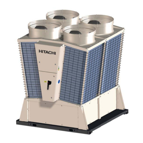
Hitachi RCUE40AG1 Manual

AIR COOLED
WATER CHILLERS
-SCREW TYPE-
Installation, Operation and Maintenance Instructions.
Design Information
Technical Catalog
RCUE40AG1-400AG1 (R407C)
Cooling Capacity 108 kW - 1068 kW


0
TABLE OF CONTENTS
1 IMPORTANT NOTICE..................................................................................................................1
2 FEATURE AND BENEFITS.........................................................................................................1
2.1
NEW CHILLER PICTURE
.............................................................................................................................1
2.2
COMPRESSOR
........................................................................................................................................2
2.3
CONTROL
...............................................................................................................................................3
2.4
HEAT EXCHANGER
...................................................................................................................................4
3 OPERATION INSTRUCTIONS ....................................................................................................5
3.1
HITACHI AIR
-
COOLER WATER CHILLER MODELS
............................................................................................5
4 COMPONENTS OF CHILLER .....................................................................................................6
4.1
STRUCTURE DRAWING
..............................................................................................................................6
5 PREPARATION INITIAL CHECK................................................................................................7
5.1
INITIAL CHECK
.........................................................................................................................................7
5.2
PLACING THE UNIT
...................................................................................................................................7
5.3
CENTRE OF GRAVITY
................................................................................................................................8
5.4
SERVICE SPACE AND FOUNDATION
.............................................................................................................9
5.5
TRANSPORTATION
...................................................................................................................................10
6 INSTALLATION ...........................................................................................................................11
6.1
ELECTRICAL WIRING
.................................................................................................................................11
6.2
WATER PIPING
.........................................................................................................................................13
6.3
TYPICAL COMMON WATER PIPING
...............................................................................................................14
6.4
MINIMUM INTERNAL SYSTEM WATER VOLUME
..............................................................................................15
6.5
WATER CONTROL
....................................................................................................................................15
6.6
BMS CONNECTION
...................................................................................................................................16
6.7
INSTALLATION FINAL CHECK
......................................................................................................................19
7 TEST RUNNING...........................................................................................................................20
7.1
PREPARATION
.........................................................................................................................................20
7.2
TEST RUNING
..........................................................................................................................................20
7.3
INSTRUCTIONS AFTER TEST RUNNING
.........................................................................................................20
8 CONTROLLER ADJUSTMENT...................................................................................................21
8.1
CONTROLLER SYSTEM
..............................................................................................................................22
8.2
CONTROLLER ADJUSTMENT
......................................................................................................................22
9 SELF-INSPECTION FUNCTIONS ..............................................................................................25
9.1
ALARM INDICATION
..................................................................................................................................25
9.2
NORMAL INDICATION
................................................................................................................................26
9.3
FUNCTION FOR INDICATION OF OPERATION CONDITION
.................................................................................26
10 CONTROL SYSTEM..................................................................................................................29
11 MAINTENANCE .........................................................................................................................40
11.1
COMPONENTS
.......................................................................................................................................40
11.2
LUBRICATION
........................................................................................................................................40
11.3
DEPOSIT
...............................................................................................................................................40
11.4
CLEANING METHOD
................................................................................................................................41
11.5
WINTER SHUTDOWN
...............................................................................................................................44
11.6
SPRING START
-
UP
.................................................................................................................................44
11.7
PART REPLACEMENT
..............................................................................................................................44
11.8
REFRIGERANT CYCLE
.............................................................................................................................44
11.9
REFRIGERANT CYCLE DIAGRAM OF HITACHI AIR
-
COOLED WATER CHILLER
.....................................................45
11.10
REFRIGERANT CYCLE DIAGRAM OF HITACHI AIR
-
COOLED WATER CHILLER
(
WITH ECONOMIZER
).......................46
11.11
COMPRESOR REMOVAL
..........................................................................................................................47
11.12
SAFETY AND CONTROL DEVICE SETTING
...................................................................................................48
11.13
NORMAL OPERATING PRESSURE
..............................................................................................................50
11.14
TEST RUNNING AND MAINTENANCE RECORD
..............................................................................................51
11.15
DAILY OPERATING RECORDS
...................................................................................................................52
11.16
SEVICING FOR
R407C
REFRIGERANT SYSTEM
..........................................................................................53
12 TROUBLESHOOTING ...............................................................................................................53

0
TABLE OF CONTENTS (cont.)
13 GENERAL SPECIFICATIONS...................................................................................................53
13.1
GENERAL DATA
.....................................................................................................................................55
14 DRAWINGS................................................................................................................................59
14.1
DIMENSIONAL DRAWING
.........................................................................................................................59
14.2
WIRING DIAGRAM
...................................................................................................................................62
15 MODEL SELECTION .................................................................................................................80
15.1
SELECTION EXAMPLE
.............................................................................................................................80
15.2
PERFORMANCE TABLE
(R407C).............................................................................................................81
15.3
ELECTRICAL DATA
(R407C)...................................................................................................................86
15.4
SOUND DATA
(R407C)..........................................................................................................................87
16 APPLICATION DATA.................................................................................................................88
16.1
WORKING RANGE
..................................................................................................................................88
16.2
PART LOAD PERFORMANCE
....................................................................................................................89
16.3
ETHYLINE GLYCOL APPLICATION
..............................................................................................................91
17 COMPONENTS DATA...............................................................................................................93
17.1
COMPRESSOR
.......................................................................................................................................93
17.2
CONDENSER AND CONDENSER FAN
.........................................................................................................93
17.3
WATER COOLER
....................................................................................................................................94

IMPORTANT NOTICE
1
/
1
1. IMPORTANT NOTICE
!HITACHI pursues a policy of continuing improvement
in design and performance of Products. The right is
therefore reserved to vary specifications without notice.
!HITACHI cannot anticipate every possible
circumstance that might involve a potential hazard.
!No part of this manual may be reproduced without
written permission.
!Signal words (DANGER, WARNING and CAUTION)
are used to identify levels of hazard seriousness.
Definitions for identifying hazard levels are provided
below with their respective signal words.
!
DANGER:
Immediate hazards which WILL result in severe
personal injury or death.
"
WARNING:
Hazards or unsafe practices which COULD result in
severe personal injury or death.
#
CAUTION:
Hazards or unsafe practices which COULD result in
minor personal injury or product or property damage.
NOTE:
Useful information for operation and/or maintenance.
!If you have any questions, contact your contractor or
dealer of HITACHI.
!This instruction gives a common description and
information for this air-cooled water Chiller which you
operate as well as for other models.
!This air-cooled water Chiller has been designed for the
following temperatures. Operate the air-cooled water
Chiller within this range.
Working Range °C
Maximum Minimum
Condenser Air
Inlet Temperature 43 5 (option: -15)
Chilled Water
Outlet Temperature 15 5
!This instructions should be considered as a permanent
part of the air-cooled water Chiller equipment and
should remain with the air-cooled water Chiller
equipment.
2. FEATURES AND BENEFITS
2.1. NEW CHILLER PICTURE
HITACHI is a world leader in technology and with continual
research and product development, now offer a screw type
Air Cooled Chillers. A wide range of capacity are
available from 108 KW to 1002KW.
Twin screw compressor is compatible with R407C and
R22, utilising the same oil and continuous capacity control
is giving the best efficiency to this system.

2
/2
FEATURES AND BENEFITS
2.2. COMPRESSOR
"
The Samurai Range incorporates
the latest development of
HITACHI´s Screw Compressor
Technology for the new
millennium.
$
Highly Reliable HITACHI Two-Pole
Motor
%
Solenoid Valve for Capacity Control
&
Built-in Oil Separator
'
Oil Sight Glass
(
Oil Heater
)
High precision Twin Screw Rotors
*
Suction Filter
"
Twin Screw Compressor
!Dual refrigerant compressor for R407C or R22 utilising
the same oil.
!By having so few moving parts, it has become highly
reliable with very low noise level and low vibration.
-LOW VIBRATION-
"
Principle of Compression
"
Continuous Capacity Control
HITACHI´s Continuous Capacity Control system uses
advanced electronic controls to position the infinitely variable
slide valve within each compressor.
This modulation allows exact load control and accurate
chilled water temperature without the need for expensive
inverters.
$
%
&
'
(
)
*
Reciprocating Screw
A
MPLITUDE (µm)
Time (second)
Discharge Port
Suction Port
Cooling load = continuos capacity control
COOLING LOAD %
Step
control
TIME (Hour)

FEATURES AND BENEFITS
2
/
3
"
Energy Saving
Thanks to Continuous Capacity Control, 15~20% energy
saving is possible compared with current step control
systems due to the following:
!The cooling load can be more closely matched
!Continuous Capacity Control takes advantage of high
efficiency part load performance.
!Frequent compressor starts and stops are eliminated.
-PART LOAD PERFORMANCE-
2.3. CONTROL
"
Many Functions
Newly developed Control Board has many functions shown
below as standard.
!REMOTE/LOCAL changeover switch
!Individual Alarm
!Pump operation circuit
!Pump Freeze Protection Control
!Reverse Phase Protection
!Time Guard
!Star Delta starting Circuit
!Easy Interface
etc...
"
Precise Temperature Control
Combination of "Continuous Capacity Control
Compressor" and "HITACHI´s unique
electronic controls" enable the Chiller to
control outlet water temperature precisely,
independent of cooling load.
This control benefits not only air-conditioning
but also industrial process use.
-CONTINUOUS CAPACITY CONTROL-
-CONVENTIONAL STEP CONTROL-
MOTOR INPUT (%)
COOLING CAPACITY (%)
Continuous
Capacity
Control
Start
Outlet Water Temperature
Load Up 2
Load Up 1
(Quick cooling)
Neutral =2°C Standard
(
Minimum 0.5°C
)
Load Down
TIME
WATER TEMPERATURE
WATER TEMPERATURE
Restart
1st step
Final step
Outlet
Tem
p
erature
Temperature
Band 7°C
(normally)

2
/4
FEATURES AND BENEFITS
2.4. HEAT EXCHANGER
"
Plate Type Evaporator
The new Samurai Chillers are equipped with plate type Heat
Exchangers, which have many advantages when compared
with conventional Shell & Tube evaporators as described
below:
!Less Refrigerant (Small Internal Volume)
!Clean (Stainless Steel)
!High efficiency (closer approach temperature)
!Plate type heat exchanger can provide improved cooling
capacity for R407C
"
Air–Cooled Condenser
HITACHI´s patented high performance SLIT FIN and inner-
grooved tube are applied to provide high performance and
compact heat exchanger
Fins are Acrylic Resin pre-coated against corrosion as
standard.
SHELL & TUBE PLATE
CAPACITY (%)

OPERATION INSTRUCTIONS
3
/
5
3. OPERATION INSTRUCTIONS
3.1. HITACHI AIR-COOLED WATER CHILLERS
To Start the Unit.
1. Open the water inlet and outlet valves.
2. After assuring that all control switches have been cut
OFF, and the "LOCAL/REMOTE" switch on the printed
circuit board is in the "REMOTE" position, turn ON the
power switch.
3. Confirm that phases R, S and T are correctly connected.
The correct phase connection can be checked by a
phase sequence indicator. If not correctly connected, the
compressor does not start due to activation of a reversal
phase protection device. Cut the main switch and
interchange two of three terminals, R, S and T at the
main power source terminals.
4. Fully open the liquid line stop valves.
5. Operate the chilled water pump.
6. Depress the "*ON" push button switch.
( * Field-Supplied )
7. Set the thermostat at the desired temperature
To Stop the Unit
1. Depress the "*OFF" push button switch.
( * Field –Supplied)
2. Switch OFF the main power source when the unit is shut
down for a long period of time.
Pilot Lamp
The red lamp indicates the normal operation.
When the red lamp is flickered or the orange lamp is
activated, any one of the safety devices may be
functioning.
Please contact your service shop, if this condition is
detected.
Daily Checking
1. Check the power supply to ensure that it is proper.
2. Check for abnormal sounds and vibration.
3. Check the unit amperage.
4. Check the operating pressure.
Troubleshooting
"
Unit Does Not Start
1. Is the main switch ON?
2. Is the main fuse OK?
3. Is the chilled water running?
4. Are the thermostats calling for the cooling operation?
"
Poor Cooling Operation
1. Is sufficient Air supplied to the condenser?
2. Are the setting temperature correct?
3. Are the operating pressures normal?
4. Is sufficient water running through the water cooler?
"
Maintenance
1. Remove any obstacles to condenser Airflow, and clean
the condenser.
2. Clean the unit with a cleaner.
3. Clean the water cooler. (It is recommended that a
specialist will be contacted for this type of work.)

4
/6
COMPONENTS OF CHILLER
4. COMPONENTS OF CHILLER
4.1. STRUCTURE DRAWING
"
HITACHI Air-Cooled Water Chiller (Example of 2 Compressor Chiller)
N°
°°
°Name N°
°°
°Name
1 Compressor 9 Operation Switch
2 Water Cooler 10 Expansion Valve
3 Condenser 11 Liquid Line Stop Valve
4 Electrical Box 12 Dryer Strainer
5 Power Wiring Supply 13 Liquid Sight Glass
6 Fan 14 Solenoid Valve
7 Check Valve 15 Regulation Valve
8 Oil Sight Glass 16 Economizer
Air Inlet
Air Outlet Air Outlet
Air Inlet Air Inlet
Water Inlet
Water Outlet
N°1 CYCLE N°2 CYCLE
Air Outlet
Detail of LPIPE structure.
Remote/ Local Changeover
Switch is Rear Side.
POWER
OPERATION
ALARM
ON OFF CHECK

PREPARATION INITIAL CHECK
5
/
7
5. PREPARATION INITIAL CHECK
5.1. INITIAL CHECK
"
Required Materials
Measure and Architectural Information Regarding
Installation Location
"
Installation Location
Confirm that the final installation location is provided with
convenient piping and wiring work. Strong water runoff
should be avoided.
"
Installation Space
Check for obstacles which restrict condenser Air flow or
hamper maintenance work in the space specified in Fig. 1.
"
Foundation
Check to ensure that the foundation is flat, level and
sufficiently strong, taking into account the maximum
foundation gradient (Fig. 2) and the unit weight balance.
Confirm elevation provision for the unit on a solid base with
an iron frame or concrete curbs shown in
chapter 4.4.
In order to obtain proper clearance beneath the unit for
either rooftop or on-the-ground installation, where
foundation bolts should be sunk into concrete. Additionally,
for on-the ground installation, provide a gravel or concrete
space around the condenser Air intake; in order to avoid
Airflow obstruction due to grass or other vegetation.
"
Unit
Check to ensure that the unit has been transported without
damage. File a damage claim with the transportation
companies if mishandling due to transportation company
negligence is suspected.
"
Transportation
Secure the route to the final installation location by
confirming the dimensions, (Refer to the "Unit General
Data" in Catalogue).
5.2. PLACING THE UNIT
!
DANGER:
If leakage is detected, stop the unit and contact the
installer or service shop. Do not use a naked fire near
the refrigerant gas. If a naked fire is utilised near the
refrigerant gas, refrigerant is turned into a harmful
phosgene compound.
"
WARNING:
This unit is operated with refrigerant R407C, (R22
option), which is non-flammable and non-poisonous.
However, refrigerant itself is heavier than the
atmosphere so that a floor is covered with refrigerant
gas if refrigerant is leaked. Therefore, keep good
ventilation to avoid choke during servicing.
#
CAUTION:
Check to ensure that valves are correctly opened. If
not opened, serious damage will occur to the
compressor due to an abnormally high pressure.
"
Tools And Instruments
Pincers, Wrenches, Facilities to Transport and Place The
Unit.
"
Transportation
Transportation the unit as close to the final installation
location as practical before unpacking is accomplished.
Provide adequate facilities to place the unit on the
foundation, with sufficient consideration given to those
individuals performing the installation.
"
Unpacking
Follow the instructions marked on the packing.
Fig.1. Operation Space
NOTE:
The height of wall shall be smaller than that of the unit
cabinet.
When the unit is installed at the location where the unit
is encircled with walls and obstruction of free Air
circulation is suspected, construction with HITACHI
regarding the operation space is recommended.
"
Maximum Foundation Gradient
The unit should be installed in an upright position within the
gradient shown in Fig.2.
Fig.2. Maximum Foundation Gradient
15 mm
30 mm
3000 mm
Overhead Air
Clearance
h1 ≤h2
h1
h2

5
/8
PREPARATION INITIAL CHECK
5.3. CENTRE OF GRAVITY
Centre of Gravity
Fig.3. Centre of Gravity
RCUE 40, 50, 60, 70AG1 RCUE 150, 180, 200AG1
RCUE 80, 100, 120,140AG1 RCUE 240, 270AG1
RCUE 300, 330AG1 RCUE 360, 400AG1
RCUE–AG1
Model 40 50 60 70 80 100 120 140 150 180 200 240 270 300 330 360 400
Location Weight Distribution (kg)
1 321 333 368 372 385 401 448 453 447 489 495 513 520 530 536 540 547
2 321 333 368 372 385 401 448 453 447 489 495 513 520 530 536 540 547
3 459 477 527 533 385 401 448 453 447 489 495 513 520 530 536 540 547
4 459 477 527 533 552 575 642 650 447 489 495 513 520 530 536 540 547
5 552 575 642 650 641 701 710 513 520 530 536 540 547
6 552 575 642 650 641 701 710 735 744 530 536 540 547
7 641 701 710 735 744 759 769 540 547
8 641 701 710 735 744 759 769 774 784
9735 744 759 769 774 784
10 735 744 759 769 774 784
11 759 769 774 784
12 759 769 774 784
13 774 784
14 774 784
Operating Weight
(Kg) 1,560 1,620 1,790 1,810 2,810 2,930 3,270 3,310 4,350 4,760 4,820 6,240 6,320 7,730 7,830 9,200 9,320
Location of Centre of Gravity (mm)
Dimension
A1,000 1,000 1,000 1,000 1,900 1,900 1,900 1,900 2,800 2,800 2,800 3,700 3,700 4,600 4,600 5,500 5,500
Dimension
B750 750 750 750 750 750 750 750 750 750 750 750 750 750 750 750 750
Centre of Gravity
Control Panel

PREPARATION INITIAL CHECK
5
/
9
5.4. SERVICE SPACE AND FOUNDATION
RCUE 40, 50, 60, 70AG1 RCUE 150, 180, 200AG1
RCUE 80, 100, 120, 140AG1 RCUE 240, 270AG1
RCUE 300, 330AG1 Detail Of Foundation
RCUE 360, 400AG1
6-Ø26
(Mounting Holes) Bottom Frame
Vibration-proof
Rubber mat
(10 positions)
4-Ø26
(Mounting Holes) Bottom Frame
Vibration-proof
Rubber mat
(6 positions)
8-Ø26
(Mounting Holes) Bottom Frame
Vibration-proof
Rubber mat
(14 positions)
Bottom Frame
Vibration-proof Rubber mat
(2 mats per position)
(OPTION)
Concrete
Steel Plate (1mm)
Rubber bush
(OPTION)
Foundation bolt
(M20)
Nut
Washer
Bottom Frame
Vibration-proof
Rubber mat
(18 positions)
10-Ø26
(Mounting Holes)
Vibration-proof
Rubber mat
(22 positions)
Bottom Frame
12-Ø26
(Mounting Holes)
Vibration-proof
Rubber mat
(26 positions)
Bottom Frame
14-Ø26
(Mounting Holes)

5
/10
PREPARATION INITIAL CHECK
5.5. TRANSPORTATION
5.5.1. Transportation by Rigging
Hook wire cables and apply field-supplied spreader bars on
the top of the unit (see figure in the next page) to prevent
the unit panels from damage due to cable scratches. The
unit should remain in an upright position even during
rigging. The wire cable to rig the unit shall be three times
stronger than the unit weight. Check to ensure that the
rigging bolts are tightly fixed to the unit. The rigging angle
shall be greater than 60° as shown. The weight of the unit
is indicated on the unit label.
!
DANGER:
Do not stand below the unit when rigging.
#
CAUTION:
Put clothes between wires and the unit to avoid
damages.
Rigging shall be performed by the instruction drawing
attached to the unit.
(Here the example of RCUE120AG1 is shown).
+
Electrical Box
,
Wire length
Min.3000mm.
(Field supplied)
-
Spreader Bar
(Field Supplied)
.
Removable
/
Rigging Holes
(4-∅50)
5.5.2. Transportation by Roller
When rolling the unit, put at least 7 equal-sized rollers
under the base frames. Each roller must carry both the
outer frames, and must be suited to balance the unit (see
the centre of gravity in page).
Fig.5.Transportation by Roller.
5.5.3. DECLINING THE UNIT DURING
TRANSPORTATION.
"
WARNING:
Do not decline the unit more than an angle of 15
°
as
shown in the figure during transportation. If declined
more than an angle of 15
°
, the unit may fall down.
Fig.6. Declining the unit.

INSTALLATION
6
/
11
6. INSTALLATION
6.1. ELECTRICAL WIRING
"
Tools and Instruments
One Set of Wiring tools and Electrical Tester (Clamp Meter)
"
Schedule Check
"
WARNING:
-
Confirm that the field-selected electrical
components (main power switch, fuses, wires,
conduit connections, wire terminals and others) are
properly selected according to the “Electrical Data“
in Technical Catalogue 1, and ensure that they
comply with national and local codes.
-
It is recommended that the main power switch be
locked in the “OFF“ position, to prevent against
accidental supply of power during equipment
servicing.
-
Check to ensure that an earthling wire is correctly
connected to the unit. This wire protects from an
electric shock. Utilisation of an earth leakage
breaker is necessary.
"
Main Power Wiring Procedures
Confirm that electrical power is not being supplied to the
installation location prior to any electrical installation work.
1. Install the field-supplied main switch box(es) at a
properly selected location.
2. Install conduit connectors in the hole for the power
wiring.
3. Lead main power wires and the earthling wire through
the connector to the screw terminals for main power and
earthling in the magnetic switch box. The neutral wires
for 380/50 Hz and 415 V/50 Hz power supply should
also be led through the connector.
4. Firmly connect the wires with wire terminals to unit
screw terminals R, S, T and N according to Fig. 7.
5. Connect the wires between the power source and the
field-supplied magnetic switches.
6. Consider that the main power source will not be left
turned OFF, easily, because it is necessary to energise
the oil heater even during unit stoppage.
Fg.7. Main Power Wiring.
N°
°°
°Name
1 Main Power/Terminal Board (R,S,T,N)
2 Electrical Box
3 Main Power Switch
4 Main Power Wiring
5 Earth Wiring
"
Control Wiring
Connect the interlock wiring and control wiring between the
unit terminals and the magnetic switches for the water
pumps, according to Fig. 8 or the wiring label. The main
connection to terminal N is required.

6
/12
INSTALLATION
Fig.8. Control Circuit Wiring.
N°
°°
°Name
1In case of remote control operation this wire
shall be removed.
2 R Phase
3 Neutral
4 Low Voltage / Remote Control
5 Run/Stop Signal
6 Alarm Signal
7 Alarm Lamp
8 Pump Operation
9 Pump Interlock
NOTE:
1. All the setting shall be performed before Power ON.
2. Remote/Local Change over Switch on Operation
Switch shall be set, to "Remote".
3. Terminals 1
!
~/ 21
!
are for AC220-240V, Terminals
A
!
~D
!
are for DC24V.
+
,
-
.
/0
1
2
3
2,3,4,5,6 Cycles
3,4,5,6 Cycles
4,5,6 Cycles
Remote control Switch (RSW-A ) (Option)
Customer Wiring
In case of Individual without Remote control Switch (6 Cycles)
ON/OFF
SETTING OF LOW VOLTAGE CONTROL
MODE
(No use low voltage control)
Dip Switch Setting
(DSW1 of Main
PCB)
NORMAL
MODE
(No Low Voltage Control)
MODE1
(Hi / Lo)
OFF
ON
MODE 2
(Pulse)
DC24V
,
5,6 Cycles
6
Cycles
Lo
Hi
min.100ms
min.100ms
Flow Switch, Differential Water
Pressure Switch Option

INSTALLATION
6
/
13
6.2. WATER PIPING
"
When Piping Connections Are Performed:
1. Connect all pipes as close as possible to the unit, so
that disconnection can be easily performed when
required.
2. It is recommended for the piping of the chilled water inlet
and outlet that flexible joints be utilised, so that vibration
will not transmit.
3. Whenever permissible, sluice valves should be utilised
for water piping, in order to minimise flow resistance and
to maintain sufficient water flow.
4. Proper inspection should be performed to check for
leaking parts inside and outside the system, by
completely opening the chilled water inlet and outlet
valves to the water cooler.
Additionally, equip valves to the inlet and outlet piping.
Equip an air purge cock on the inlet piping and a drain
cock on the outlet piping. The cock handle should be
removed so that the cock can not be opened under
normal circumstances. If this cock is opened during
operation, trouble will occur due to water blow-off.
5. Sufficiently perform insulation to keep the chilled water
piping cool and to prevent sweating of the piping.
6. Under the condition where the ambient temperature is
low in winter, there is a case where equipment and
piping will become damaged during the shutdown
periods at night, because the water in the pump or
piping will be frozen. To prevent freezing of the water, it
is effective to operate the pumps.
HITACHI Chiller has the pump ON/OFF operation
control. (see Wiring Diagram) water from piping.
Additionally, in a case where measures such as water
draining are difficult, utilise antifreeze mixture of
ethylene glycol type or propylene glycol type.
7. The common water pipes (Inlet/Outlet) are field
supplied, only for RCUE 150 ∼400AG1. Typical pipe
working examples are indicated on page 10.
It is no necessary to install any sensor in these common
pipes for standard models.
Number connections for models:
Models Water Inlet Water Outlet
RCUE 40, 50, 60, 70AG1 1 1
RCUE 80, 100, 120, 140AG1 1 1
RCUE 150, 180, 200AG1 2 2
RCUE 240, 270AG1 2 2
RCUE 300, 330AG1 3 3
RCUE 360, 400AG1 3 3
#
CAUTION:
This product is equipped with plate type heat
exchanger. In the plate heat exchanger, water flows
through a narrow space between the plates.
Therefore, there is a possibility that freezing may
occur if foreign particles or dust are clogged. In order
to avoid this clogging. 20 mesh water strainer shall
be attached at the inlet of chilled water piping
near the product. In case of punching metal type
strainer, mesh hole size shall be
∅
2mm or less.
Never use the salt type antifreeze mixture, because it
possesses strong corrosion characteristics, and water
equipment will be damaged.
+
Pressure Gauge
,
Strainer
-
Flexible Joint
.
Valve
Water Inlet
Water Outlet
Chiller

6
/14
INSTALLATION
6.3. TYPICAL COMMON WATER PIPING
RCUE 150, 180, 200, 240, 270AG1
RCUE 300, 330, 360, 400AG1
Field piping
(Field supplied) HITACHI standard
NOTES:
1. Provide a 20 mesh water strainer at the
Chiller water inlet.
2. Securely connect the chilled water pipe o
f
each cooler in the same water system.
3. Support the water pipes with stay not to
give the weight of water pipes directly to
the unit.
Dimensions according to MODELS
14B Victaulic connection. (Attached with unit) 6Chilled water Inlet (6B Flange)
2Small Pipe (Attached with unit) 7Chilled water Outlet (6B Flange)
3Electrical Box 8Drain plug
4Thermal insulation 9To be welded to the common water pipe
5Air purge plug 10 Water strainer (20 mesh: field supplied)
With bending connection
Dimensions according to MODELS
14B Victaulic connection. (Attached with unit) 6Chilled water Inlet (8B Flange)
2Small Pipe (Attached with unit) 7Chilled water Outlet (8B Flange)
3Electrical Box 8Drain plug
4Thermal insulation 9To be welded to the common water pipe
5Air purge plug 10 Water strainer (20 mesh: field supplied)
NOTES:
3. Provide a 20 mesh water strainer at the
Chiller water inlet.
4. Securely connect the chilled water pipe o
f
each cooler in the same water system.
3. Support the water pipes with stay not to
give the weight of water pipes directly to
the unit.
Field piping
(Field supplied) HITACHI standard

INSTALLATION
6
/
15
6.4. MINIMUM INTERNAL SYSTEM WATER VOLUME
To ensure the cooling operation at least 5 minutes without
interruption, the internal chilled water volume in the piping
system should be greater than the minimum volume as
shown below.
NOTE:
Minimum internal system water volume written above is
for standard ON/OFF differential, minimum internal
system water volume shall be increased by the setting of
differential.
MODEL RCUE AG1 40 50 60 70 80 100 120 140 150 180 200 240 270 300 330 360 400
Minimum
Internal Water Volume m³ 0.64 0.58 0.70 0.78 1.28 1.16 1.40 1.56 1.74 2.10 2.34 2.80 3.12 3.50 3.90 4.20 4.68
Internal
Volume in Water Cooler litre 10.8 13.3 16.1 16.1 23.9 30.7 38.2 38.2 44.0 54.3 54.3 76.4 76.4 82.2 82.2 114.6 114.6
6.5. WATER CONTROL
#
CAUTION:
When industrial water is applied for chilled water and
condenser water, industrial water rarely causes
deposits of scales or other foreign substances on
equipment. However, well water or river water may in
most cases contain suspended solid matter, organic
matter, and scales in great quantities. Therefore,
such water should be subjected to filtration or
softening treatment with chemicals before application
as chilled water.
It is also necessary to analyse the quality of water by
checking pH, electrical conductivity, ammonia ion
content, sulphur content, and others, and to utilise
industrial water only if problem is encountered
through these check.
The following is the recommended standard water quality.
Chilled Water System Tendency
(1)
Item Circulating Water
(20 °
°°
°C Less than) Supply Water Corrosion Deposits of
Scales
Standard Quality
pH (25 °C) 6.8 ~ 8.0 6.8 ~ 8.0 ##
Electrical Conductivity (mS/m) (25°C)
{µS/cm} (25 °C)
(2)
Less than 40
Less than 400
Less than 30
Less than 300 ##
Chlorine Ion (mg CI¯/I) Less than 50 Less than 50 #
Sulphur Acid Ion (mg SO
42
¯/I) Less than 50 Less than 50 #
The Amount of Acid Consumption (pH 4.8)
(mg CaCO
3
/I) Less than 50 Less than 50 #
Total Hardness (mg CaCO
3
/I) Less than 70 Less than 70 #
Calcium Hardness (mg CaCO
3
/I) Less than 50 Less than 50 #
Silica L (mg SIO
2
/I) Less than 30 Less than 30 #
Reference Quality
Total Iron (mg Fe/I) Less than 1.0 Less than 0.3 ##
Total Cupper (mg Cu/I) Less than 1.0 Less than 0.1 #
Sulphur Ion (mg S
2
¯/I) It shall not be detected. #
Ammonium Ion (mg NH
4+
/I) Less than 1.0 Less than 0.1 #
Remaining Chlorine (mg CI/I) Less than 0.3 Less than 0.3 #
Floating Carbonic Acid (mg CO
2
/I) Less than 4.0 Less than 4.0 #
Index of Stability 6.8 ~ 8.0 - ##
NOTE:
1. The mark "
#
" in the table means the factor
concerned with the tendency of corrosion or deposits
of scales.
2. The value showed in "
{}
" are for reference only
according to the former unit.

6
/16
INSTALLATION
6.6. BMS CONNECTION
6.6.1. SYSTEM
BMS connection is available by using HARC70-CE1,
optional BMS interface unit.
One interface HARC70-CE1 can connect up to 4
Chillers from a remote place using H-Link connection
(Hitachi communications protocol).
Protocol used by HARC70-CE1 is LonWorks. Physical
channel connection with interface is FTT-10A.
6.6.2. SIGNAL
ON/OFF Chiller
Control
Operation Outlet Water Setting
ON/OFF
Chilled Water Outlet
Setting
Chilled Water Outlet
Temp.
Chilled Inlet Water Temp.
Alarm Codes
State
Monitoring
Operation status
6.6.3. CAUTION ON USE HARC70-CE1
Please use it correctly according to the following
"CAUTION ON USE.”
As for the following:
!“HARC” indicate “ HARC70-CE1”
!“Monitoring Device “ indicate “ upper connecting
device for supervise “, and
!“Control Panel” indicate “Control panel of Chiller unit”.
!“SNVT” Indicate “Standard Network Variables Types”
1.Install HARC in a grounded metal box.
2.Install a short circuit breaker in the power supply of
HARC.
3.The transmission line between HARC and Chiller unit
should be “0.75mm
2
twisted-Pair cable”. If it is not
used, then it cannot communicate between HARC
and Chiller unit, and it does not work properly.
.
3. After an abnormal transmitting occurs between
HARC and Chiller unit, and Chiller unit stops, in the
case of operation starting by the hand operation,
then once turn off Chiller unit’s power supply, and
turn on the power supply. If it isn’t carried out, then
Chiller unit keeps the condition of transmission
alarm.
4. After an abnormal transmitting occurs between
HARC and Chiller unit, and Chiller unit stops, in the
case of operation starting by Monitoring Device,
then transmit an operation order after you transmit a
stop order once. If it isn’t carried out, it can't start.
6. After Chiller unit, under control by HARC, is stopped
by the control panel, and operation is done from the
Monitoring Device, then transmit an operation order
after you transmit a stop order once. If it isn’t carried
out, it can’t start.
7. Don't set the setting temperature to Chiller unit,
under control by HARC, by the control panel. If it is
done the, setting temperature is changed. And, as
for the setting temperature, which changed in this
case, transmit to Monitoring device.
8. After the setting temperature is changed by
Monitoring Device, in the case of turned off Chiller
unit’s power supply, set the setting temperature by
Monitoring device again. If it isn’t carried out, then
the setting temperature becomes to the temperature
by setting control panel.
9. If power failure occurs in Chiller unit, under control
by HARC, it may not revert to the condition before
the power failure. Try to detect that the operation
condition of Chiller unit changed, by the Monitoring
Device. If Chiller unit stopped due to the power
failure, then transmit an operation order from the
Monitoring Device after the power supply
restoration. And, transmit the setting temperature,
mode from the Monitoring device. If it isn’t carried
out, and then Chiller unit is stopping, and the setting
temperature, mode is the initialisation value by
Chiller unit.
10.When SNVT which is transmitted from HARC, is used
by other control device, premise that there is two
minutes delay between the transmitting SNVT and
the movement Chiller unit . If it isn’t premised, then
a problem may occurs in the control system.
11.Don't interrupt the power supply of HARC when you
use SCPT in HARC. Even if it exceeds
MaxSendTime, when SNVT is not transmitted from
HARC, and SNVT is transmitted below with the
setting value of MinSendTime, then transmit SCPT
again . If it isn’t carried out, SCPT value continues
maintaining “0”.
12.If the setting of control panel change Remote to
Locally, and set Remote again, then set the setting
temperature and mode from the Monitoring Device
again. If it does not set, then the setting temperature
and mode continue maintaining the initialisation
value by Chiller unit.
13.When the abnormal transmitting occurs between the
Monitoring Device and HARC, then the condition of
the Monitoring Device may not correspond with the
condition of HARC. Set MaxSendTime and, try that
the condition of the Monitoring Device corresponds
with the condition of HARC in the interval of
MaxSendTime .
14.It can't be used with the except for “ stop signal of
input terminal of Chiller unit “.
Chiller 1 Chiller 2 Chiller 3 Chiller 4
HARC70-CE1
Upper Monitoring Devide
H-Link
LonWorks
This manual suits for next models
16
Table of contents
Other Hitachi Chiller manuals
Popular Chiller manuals by other brands

SMC Networks
SMC Networks HRR012-A*-20 Series operating manual

Eurodifroid
Eurodifroid KR Series Installation and operating instructions

Parker
Parker Hyperchill ICE076 user manual

SMC Networks
SMC Networks Thermo-con HEF002-A6 manual

Trane
Trane TCK024B1 Installation operation & maintenance

Ferroli
Ferroli RCA Series Installation, maintenance and user manual