Parker Hyperchill ICE076 User manual

Hyperchill pCO5 (50Hz) ICE076
ICE090
ICE116
DATE: 23.09.2022 - Rev. 00
CODE: 398H271838
IT Manuale d’uso
EN User Manual
ES Manual de uso
DE Benutzer Handbuch
FR Manuel d’utilisation
PT Manual do utilizador


Italiano 1/10
Hyperchiller 076-116
1 Sicurezza
1.1 Importanza del manuale
• Conservarlo per tutta la vita della macchina.
• Leggerlo prima di qualsiasi operazione.
• E’ suscettibile di modiche: per una informazione aggiorna-
ta consultare la versione a bordo macchina
1.2 Segnali di avvertimento
!Istruzione per evitare pericoli a persone.
YIstruzione da eseguire per evitare danni all’apparecchio.
ZE’ richiesta la presenza di tecnico esperto e autorizzato.
,Sono presenti simboli il cui signicato è nel paragrafo 7.
1.3 Indicazioni di sicurezza
! Ogni unità è munita di sezionatore elettrico per intervenire
in condizioni di sicurezza. Usare sempre tale dispositivo per
eliminare i pericoli durante la manutenzione.
!Il manuale è rivolto all’utente nale solo per operazioni ese-
guibili a pannelli chiusi: operazioni che ne richiedono l’apertura
con attrezzi devono essere eseguite da personale esperto e
qualicato.
YNon superare i limiti di progetto riportati nella targa dati.
! Y È compito dell’utilizzatore evitare carichi diversi dalla
pressione statica interna. Qualora sussista il rischio di azioni
sismiche l’unità va adeguatamente protetta.
Impiegare l’unità esclusivamente per uso professionale e per lo
scopo per cui è stata progettata.
E’ compito dell’utilizzatore analizzare tutti gli aspetti dell’appli-
cazione in cui il prodotto è installato, seguire tutti gli standards
industriali di sicurezza applicabili e tutte le prescrizioni inerenti
il prodotto contenute nel manuale d’uso ed in qualsiasi docu-
mentazione prodotta e fornita con l’unità.
La manomissione o sostituzione di qualsiasi componente da
parte di personale non autorizzato e/o l’uso improprio dell’unità
esonerano il costruttore da qualsiasi responsabilità e provoca-
no l’invalidità della garanzia.
Si declina ogni responsabilità presente e futura per danni a
persone, cose e alla stessa unità, derivanti da negligenza degli
operatori, dal mancato rispetto di tutte le istruzioni riportate nel
presente manuale, dalla mancata applicazione delle normative
vigenti relative alla sicurezza dell’impianto.
Il costruttore non si assume la responsabilità per eventuali dan-
ni dovuti ad alterazioni e/o modiche dell’imballo.
E’ responsabilità dell’utilizzatore assicurarsi che le speciche
fornite per la selezione dell’ unità o di suoi componenti e/o
opzioni siano esaustive ai ni di un uso corretto o ragionevol-
mente prevedibile dell’unità stessa o dei componenti.
ATTENZIONE: Il costruttore si riserva il diritto di modifica-
re le informazioni contenute nel presente manuale senza
alcun preavviso. Ai fini di una completa ed aggiornata infor-
mazione si raccomanda all’utente di consultare il manuale
a bordo unità.
1.4 Rischi residui
L’installazione, l’avviamento, lo spegnimento, la manutenzio-
ne della macchina devono essere tassativamente eseguiti in
accordo con quanto riportato nella documentazione tecnica del
prodotto e comunque in modo che non venga generata alcuna
situazione di rischio.
I rischi che non è stato possibile eliminare in fase di progetta-
zione sono riportati nella tabella seguente.
Parte
conside-
rata
Rischio
residuo
Modalità Precauzioni
batteria di
scambio
termico
piccole ferite
da taglio
contatto evitare il contatto, usa-
re guanti protettivi
griglia
ventilatore e
ventilatore
lesioni inserimento di
oggetti appuntiti
attraverso la griglia
mentre il ventilatore
sta funzionando
non inlare oggetti di
alcun tipo dentro la
griglia dei ventilatori
e non appoggiare og-
getti sopra le griglie
interno unità:
compressore
e tubo di
mandata
ustioni contatto evitare il contatto, usa-
re guanti protettivi
interno unità:
parti metal-
liche e cavi
elettrici
intossicazio-
ni, folgora-
zione, ustioni
gravi
difetto di isolamen-
to cavi alimenta-
zione a monte del
quadro elettrico
dell’unità. Parti me-
talliche in tensione
protezione elettrica
adeguata della linea
alimentazione. Mas-
sima cura nel fare il
collegamento a terra
delle parti metalliche
esterno
unità:
zona circo-
stante unità
intossi-
cazioni,
ustioni
gravi
incendio a causa
corto circuito o
surriscaldamen-
to della linea
alimentazione a
monte del quadro
elettrico dell’unità
sezione dei cavi e si-
stema di protezione
della linea alimen-
tazione elettrica
conformi alle norme
vigenti
8 Appendice
Indice
1 Sicurezza 1
1.1 Importanza del manuale ......................................................1
1.2 Segnali di avvertimento .......................................................1
1.3 Indicazioni di sicurezza........................................................1
1.4 Rischi residui ......................................................................1
2 Introduzione 2
2.1 Trasporto .............................................................................2
2.2 Movimentazione ..................................................................2
2.3 Ispezione .............................................................................2
2.4 Immagazzinaggio.................................................................2
3 Installazione 2
3.1 Spazio operativo..................................................................2
3.2 Fondazioni ...........................................................................2
3.3 Versioni ................................................................................2
3.4 Circuito idraulico..................................................................2
3.5 Circuito elettrico ..................................................................3
3.6 Versione ad acqua (W).........................................................3
4 Controllo 4
4.1 Pannello di controllo............................................................4
4.2 Avviamento/Spegnimento ...................................................4
4.3 Visualizza delle sonde..........................................................5
4.4 Visualizza uscite digitali/ingressi analogici ..........................5
4.5 Denizione parametri...........................................................5
4.6 Paramteri diretti (DIrE) .........................................................5
4.7 Parametri service (USER) ....................................................6
4.8 Funzionamento chiller..........................................................7
4.9 Segnalazione allarme...........................................................7
4.10 Riavvio automatico............................................................7
5 Opzioni 8
5.1 Controllo precisione
(controllo pCOS).........................................................................8
5.2 Bassa temperatura ambiente (-10C°)
(controllo pCOS).........................................................................8
5.3 Controllo precisione + Bassa temp. amb. (-10C°)
(controllo pCOM) ........................................................................8
5.4 Bassa temperatura ambiente L2 (-20/30 C°)
(controllo pCOM) ........................................................................8
6 Manutenzione 9
6.1 Avvertenze generali .............................................................9
6.2 Manutenzione preventiva.....................................................9
6.3 Refrigerante .........................................................................9
6.4 Smantellamento...................................................................9
7 Ricerca guasti 10

Italiano 2/10
2 Introduzione
I refrigeratori d’acqua sono unità monoblocco per la produzione
di acqua refrigerata in circuito chiuso. I motori di compressore,
pompa e ventilatore, sono dotati di una protezione termica che
li protegge da eventuali surriscaldamenti.
2.1 Trasporto
L’unità imballata deve rimanere:
a) In posizione verticale;
b) Protetta da agenti atmosferici;
c) Protetta da urti.
2.2 Movimentazione
Usare carrello elevatore a forca adeguato al peso da sollevare,
evitando urti di qualsiasi tipo (vedere paragrafo 7.3).
2.3 Ispezione
a) In fabbrica tutte le unità sono assemblate, cablate, caricate
con refrigerante ed olio e collaudate;
b) ricevuta la macchina controllarne lo stato: contestare subito
alla compagnia di trasporto eventuali danni;
c) disimballare l’unità il più vicino possibile al luogo dell’instal-
lazione.
2.4 Immagazzinaggio
a) Mantenere l’unità imballata in luogo pulito e protetto da
umidità e intemperie;
b) Non sovrapporre le unità;
c) Seguire le istruzioni riportate sull’imballo.
3 Installazione
Y Per una installazione ottimale rispettare le indicazioni ripor-
tate nel capitolo 7.
!La macchina deve essere installata in ambienti adegua-
tamente protetti contro rischi di incendio (riferimento norma
EN378-3)
!Liquidi da raffreddare
I liquidi da raffreddare devono essere compatibili con i materiali
utilizzati.
Esempi di liquidi usati sono acqua o miscele di acqua e glico-
le etilenico o propilenico.
I liquidi da raffreddare non devono essere inammabili.
Se i liquidi da raffreddare contengono sostanze pericolose
(come ad esempio il glicole etilenico/propilenico) l’eventuale
liquido fuoriuscito da una zona di perdita deve essere raccolto
perchè dannoso per l’ambiente. In caso di svuotamento del cir-
cuito idraulico, attenersi alle normative vigenti e non disperdere
il contenuto nell’ambiente.
3.1 Spazio operativo
Per consentire il libero passaggio del usso d’aria e la manu-
tenzione dell’unità, è necessario lasciare libera da ostruzioni
una area minima attorno al refrigeratore (vedere paragrafo 7.4).
Lasciare almeno 2 metri di spazio sopra il refrigeratore nei mo-
delli ad espulsione verticale dell’aria di condensazione.
3.2 Fondazioni
L’unità deve essere posizionata su una superce livellata che
supporti il suo peso.
Per la distribuzione del peso vedere paragrafo 7.5 - Posizioni e
carichi appoggi.
3.3 Versioni
Versione ad aria
Non creare situazioni di ricircolo dell’aria di raffreddamento.
Non ostruire le griglie di ventilazione. Per le versioni con ventila-
tori assiali è sconsigliata la canalizzazione dell’aria esausta.
Versione ad acqua (W)
Se l’acqua al condensatore è in circuito aperto, installare ltro a
rete su ingresso acqua di condensazione.
Per particolari acque di raffreddamento (deionizzata, deminera-
lizzata, distillata) imateriali standard previsti per il condensatore
potrebbero non essere adatti. In questi casi si prega di contat-
tare il costruttore.
3.4 Circuito idraulico
3.4.1 Controlli e collegamento
Y Prima di collegare il refrigeratore e riempire il circuito, assi-
curarsi che le tubazioni siano pulite. In caso contrario effettuare
un lavaggio accurato.
Y Se il circuito idraulico è di tipo chiuso, in pressione, è con-
sigliabile installare una valvola di sicurezza tarata a 6 bar.
Y Si consiglia di installare sempre dei ltri a rete sulle tuba-
zioni di ingresso e uscita acqua.
Y Nel caso in cui il circuito idraulico sia intercettato da val-
vole automatiche, proteggere la pompa con sistemi anti colpo
d’ariete.
Controlli preliminari
1) Controllare che le eventuali valvole di intercettazione del
circuito idraulico siano aperte.
2) Se il circuito idraulico è di tipo chiuso, controllare che sia
stato installato un vaso d’espansione di capacità adeguata.
Vedere paragrafo 3.4.3.
Collegamento
1) Collegare il refrigeratore d’acqua alle tubazioni di ingresso e
uscita, utilizzando gli appositi attacchi posizionati nella parte
laterale dell’unità.
Si consiglia l’utilizzo di giunti essibili per togliere rigidità al
sistema.
2) Riempire il circuito idraulico utilizzando l’apposito attacco di
carica posizionato nella parte posteriore del refrigeratore.
3) Si consiglia di dotare le tubazioni di ingresso ed uscita di un
valvole, in modo da poter escludere la macchina dal circuito
in caso di manutenzione e di regolazione per la pompa.
4) Se il chiller lavora con vasca aperta, la pompa deve essere
installata in aspirazione alla vasca e in mandata al chiller.
Controlli successivi
1) Controllare che il serbatoio ed il circuito siano completa-
mente riempiti d’acqua e correttamente satati dall’aria.
2) Il circuito idraulico dev’essere sempre riempito. A tal ne si
può provvedere ad un controllo e rabbocco periodico.
Controlli qualità dell’acqua
Se non previsto in fornitura, installare ltro a rete su ingresso
acqua (cap. 7.4)
Y, Caratteristiche dell’acqua in ingresso/ingresso conden-
satore
Temperatura ≥50°F (10°C) CL-<50 ppm
ΔT IN/OUT 5-15°C CaCO370-150 ppm
Max % glicole 50 O2<0.1 ppm
Pressione 43.5-145 PSIg
(3-10 barg) Fe <0.2 ppm
PH 7.5-9 NO3<2 ppm
Conduttività
elettrica 10-500 μS/cm HCO3-70-300 ppm
Indice di
saturazione di
Langelier
0-1 H2S<0.05 ppm
SO4
2- <50 ppm CO2<5 ppm
NH3<1 ppm Al <0.2 ppm
Per particolari acque di raffreddamento (deionizzata, demi-
neralizzata, distillata) i materiali standard previsti per il chiller
potrebbero non essere adatti. In questi casi si prega di contat-
tare il costruttore.
3.4.2 Acqua e glicole etilenico
Se installato all’aperto, o comunque in ambiente chiuso non
riscaldato, c’è la possibilità che, nei periodi di fermata dell’im-
Hyperchiller 076-116

Italiano 3/10
Hyperchiller 076-116
pianto in corrispondenza ai mesi più freddi dell’anno, l’acqua
all’interno del circuito ghiacci.
Per evitare questo pericolo si può:
a) Dotare il refrigeratore di adeguate protezioni antigelo, forni-
te dal costruttore come opzionali;
b) Scaricare l’impianto tramite l’apposita valvola di scarico, in
caso di fermate prolungate;
c) Aggiungere un’adeguata quantità di antigelo all’acqua di
circolazione (vedi tabella).
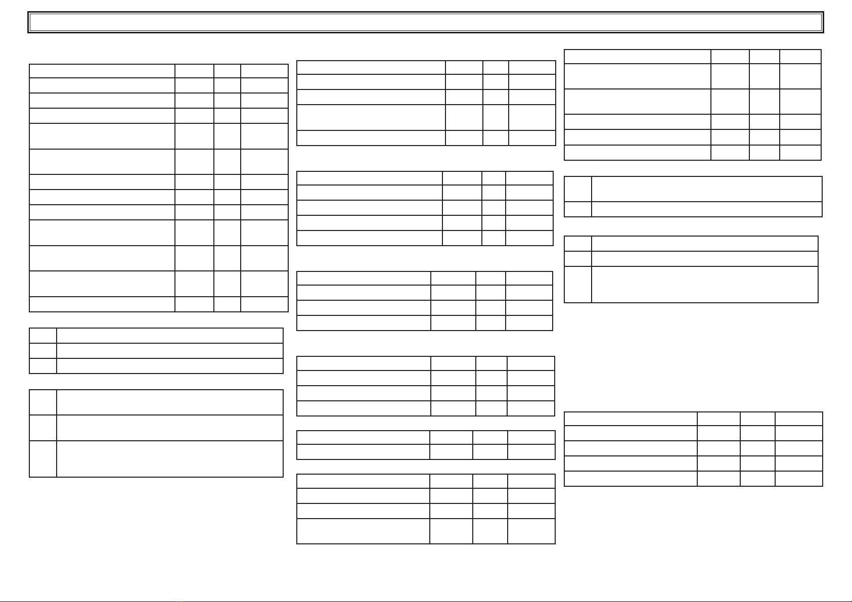
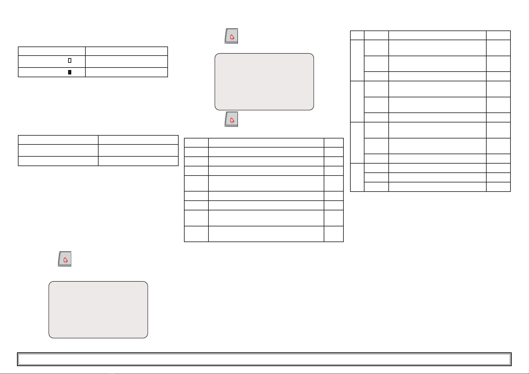
A volte la temperatura dell’acqua in uscita è tale da richiede-
re che essa venga miscelata con glicole etilenico, per evitare
formazioni di ghiaccio, nelle percentuali sotto riportate.
Temperatura acqua
in uscita [°C]
Glicole etilenico
(% vol.)
Temperatura
ambiente
45-2
210-5
015-7
-2 20 -10
-4 25 -12
-6 30 -15
3.4.3 Vaso d’espansione
Per evitare che gli aumenti o diminuzioni di volume del uido
conseguenti ad una variazione sensibile della sua temperatura
possano danneggiare la macchina o il circuito, è consigliabile
installare un vaso d’espansione di capacità adeguata.
Il vaso d’espansione va installato in aspirazione alla pompa
sull’attacco posteriore del serbatoio.
Per un calcolo del volume del vaso d’espansione da applicare
ad un circuito chiuso si può utilizzare la formula seguente:
V=2 x Vtot x (Pt min - P t max)
dove
Vtot= vol. totale del circuito (in litri)
P t min/max = peso specico alla minima/massima temperatura
raggiungibile dall’acqua [kg/dm3].
I valori di peso specico in funzione della temperatura e della
percentuale di glicole, sono riportati in tabella.
%
glico-
le
Temperatura [°C]
-100 1020304050
0% 1.0024 1.0008 0.9988 0.9964 0.9936 0.9905 0.9869
10% 1.0177 1.0155 1.0130 1.0101 1.0067 1.0030 0.9989
20% 1.0330 1.0303 1.0272 1.0237 1.0199 1.0156 1.0110
30% 1.0483 1.0450 1.0414 1.0374 1.0330 1.0282 1.0230
!Attenzione: In fase di riempimento fare riferimento ai
dati di carica anche del vaso di espansione.
3.5 Circuito elettrico
3.5.1 Controlli e collegamenti
!Prima di effettuare qualsiasi operazione su parti elettriche
assicurarsi che non vi sia tensione.
Tutte le connessioni elettriche devono essere conformi alle
prescrizioni locali del luogo di installazione.
Controlli iniziali
1) La tensione e la frequenza di rete devono corrispondere
ai valori stampigliati sulla targhetta dati del refrigeratore.
La tensione di alimentazione non deve, neppure per brevi
periodi, essere fuori dalla tolleranza riportata sullo schema
elettrico che, salvo diverse indicazioni, è pari +/- 10% per la
tensione; +/- 1% sulla frequenza.
2) La tensione deve essere simmetrica (valori efcaci delle
tensioni ed angoli di fase fra fasi consecutive uguali fra loro).
Il massimo squilibrio ammesso fra le tensioni è pari al 2%
Collegamento
1) L’alimentazione elettrica dei refrigeratori viene effettuata
con cavo a 4 li , 3 poli +terra, senza neutro. Per la sezione
vedere paragrafo 7.5.
2) Passare il cavo attraverso il pressacavo posto sul pannel-
lo posteriore della macchina e collegare fase e neutro ai
morsetti del sezionatore generale (QS), la terra va collegata
all’apposito morsetto di terra (PE).
3) Assicurare all’origine del cavo di alimentazione una protezio-
ne contro i contatti diretti pari ad almeno IP2Xo IPXXB.
4)Installare , sulla linea di alimentazione elettrica del refrigera-
tore, un interruttore automatico con differenziale 0.3A, della
portata massima indicata nello schema elettrico di riferimen-
to, con potere di interruzione adeguato alla corrente di corto
circuito esistente nella zona d’installazione della macchina.
La corrente nominale “In” di tale magnetotermico deve esse-
re uguale a FLA e la curva di intervento di tipo D.
5) Valore massimo dell’impedenza di rete = 0.274 ohm.
Controlli successivi
Assicurarsi che la macchina e le apparecchiature ausiliarie
siano state messe a terra e protette contro cortocircuiti e/o
sovraccarichi.
!Una volta che l’unità è stata collegata e l’interruttore
generale a monte è stato chiuso (dando così tensione alla
macchina), il voltaggio nel circuito elettrico raggiunge valori
pericolosi. Massima precauzione!
3.5.2 Allarme generale
Tutti i refrigeratori sono provvisti della segnalazione allarme
macchina (vedere schema elettrico), costituita da un contatto
libero in scambio riportato in morsettiera: ciò permette di allac-
ciare un allarme centralizzato esterno, acustico, visivo o inserito
in logiche es. PLC.
3.5.3 ON/OFF remoto
Tutti i refrigeratori hanno la possibilità di avere un comando di
avviamento e fermata remoto.
Per il collegamento del contatto ON-OFF remoto vedere lo
schema elettrico.
3.6 Versione ad acqua (W)
I chiller in versione con condensazione ad acqua, necessitano
di un circuito idraulico che porti l’acqua fredda al condensatore.
Il chiller in versione ad acqua è dotato di una valvola presso-
statica, in entrata al condensatore, la cui funzione è quella di
regolare la portata d’acqua in modo da ottenere sempre una
condensazione ottimale.
Controlli preliminari
Se l’alimentazione di acqua al condensatore viene realizzata
tramite circuito chiuso, effettuare tutti i controlli preliminari elen-
cati per il circuito idraulico principale (paragrafo 3.3.1).
Collegamento
1) Si consigliadidotare il circuito acqua di condensazione di
valvole di intercettazione, in modo da poter escludere la mac-
china in caso di manutenzione.
2) Collegare le tubazioni dimandata/ritorno acqua agli appositi
attacchi posti sul retro dell’unità.
3) Se l’acqua di condensazione è ” a perdere”, si consiglia di
dotare il circuito di un ltro in ingresso al condensatore, in
modo da limitare il rischio di sporcamento delle superci.
4) Se il circuito è di tipo chiuso, vericare che sia ben riempito
d’acqua e correttamente satato dall’aria.

Italiano 4/10
4 Controllo
4.1 Pannello di controllo
Display
P0 Interruttore sezionatore.
P1 Visualizza sul display gli allarmi, spegne il
cicalino se attivo e resetta gli allarmi.
P2 Fa accedere al menu per la selezione del
gruppo di parametri.
P3 Annulla una operazione.
P4 Sposta il cursore o incrementa il valore di un
parametro.
P5 Sposta il cursore o decrementa il valore di
un
parametro.
P6 Sposta il cursore da un parametro all’altro o
conferma un parametro.
LED Acceso Spento Lampeggiante
P1 - Nessun allarme
presente
Presenza di
un allarme.
P2 Macchina
accesa.
Macchina
spenta.
-
! Attenzione: attendere 30 secondo per l’avvio del programma.
4.2 Avviamento/Spegnimento
4.2.1 Riscaldamento compressore
• Dare tensione ruotando l’INTERRUTTORE GENERALE QS
[P0] su “ ON”.
(Solo per opzione L2: !Y LA RESISTENZA CARTER DEVE
ESSERE INSERITA 24 ORE PRIMA DI AVVIARE LA MACCHI-
NA).
Un’incorretta operazione può danneggiare seriamente il com-
pressore frigorifero.
• Mettere in ON il refrigeratore come in gura.
• Impostare sul controllore la temperatura desiderata.
Avviamento
Status Unit : OFF
Pump :
Compressor 1 :
Compressor 2 :
premere il tasto (P2) per entrare nel menu principale.
premere il tasto (P5) per selezionare il parametro “On”.
Main menu 1/7
On
OFF
USER
premere il tasto (P6) per confermare.
ON
appare la scritta “ON” con la freccia lampeggiante.
premere il tasto (P6) per avviare il chiller.
Water Outlet Temp.
b1 : 7.0 C°
Pump :
Compressor 1 :
Compressor 2 :
Simbolo Stato Descrizione
sso OFF
sso ON
lampeggiante In attesa di partire
4.2.2 Regolazioni al primo avviamento
a) Regolazione temperatura. Se si vuole effettuare una nuova
regolazione vedere paragrafo 4.5.
b) Vericare il corretto funzionamento della pompa utilizzando
il manometro (leggere P1 e P0) e i valori limite di pressione
(Pmax e Pmin) riportati sulla targa dati della pompa.
P1 = pressione con pompa ON
P0 = pressione con pompa OFF
Pmin < (P1-P0) < Pmax
- Esempio n°1.
Condizioni:
circuito chiuso a pressione P0 di 2 bar
dati targa pompa: Pmin 1bar/ Pmax 3bar
regolare l’uscita valvola per una pressione di 3bar< P1< 5Bar
- Esempio n°2.
Condizioni:
circuito aperto a pressione P0 di 0 bar
dati targa pompa: Pmin 1bar/ Pmax 3bar
regolare l’uscita valvola per una pressione di 1bar< P1< 3Bar
c) Vericare il corretto funzionamento della pompa anche in
condizioni di regime.
Vericare inoltre che l’amperaggio della pompa sia entro i
limiti di targa.
d) Spegnere il chiller e procedere con il rabbocco del circuito
idraulico con la temperatura di “SET”.
e) Controllare che la temperatura dell’acqua “trattata” non
scenda sotto i 5°C e la temperatura ambiente in cui opera
il circuito idraulico non scenda sotto 5°C. In caso contrario
aggiungere all’acqua l’opportuna quantità di glicole, come
spiegato nel paragrafo 3.4.2
Display
Hyperchiller 076-116

Italiano 5/10
Hyperchiller 076-116
4.2.3 Spegnimento
Water Outlet Temp.
b1 : 7.0 C°
Pump :
Compressor 1 :
Compressor 2 :
premere il tasto (P2) per entrare nel menu principale.
premere il tasto (P5) per selezionare OFF
premere il tasto (P6) per per confermare.
OFF
appare la scritta “OFF” con la freccia lampeggiante
premere il tasto (P6) per spegnere il chiller
Attenzione: Non mettere in off il sezionatore generale QS
[P0] in modo da garantire l’alimentazione di eventuali resi-
stenze antigelo presenti nel refrigeratore.
4.3 Visualizza delle sonde
Water Outlet Temp.
b1 : 7.0 C°
Pump :
Compressor 1 :
Compressor 2 :
1) premere il tasto (P5) per visualizzare le altre sonde.
Water Outlet Temp.
b2 : 5.0 C°
Pump :
Compressor 1 :
Compressor 2 :
Dopo qualche minuto ritorna alla sonda B1.
4.4 Visualizza uscite digitali/ingressi analogici
Premere ripetutamente il tasto (P5) per visualizzare
le uscite digitali e gli ingressi analogici disponibili
DIGITAL OUTPUT
Pump :
Compressor 1 :
Compressor 2 :
A/Freeze :
Gen.Alarm :
Unit Status :
ANALOG INPUT
b1 : 10.0 C°
b2 : 7.0 C°
b3 : 20.0 C°
b5 : 20.0 C°
4.5 Definizione parametri
Generalità
Esistono tre livelli di scelta parametri:
a) DirE (D): con accesso immediato: destinati al utente
b) User (U): con accesso con password: destinati a persona-
le service;
c) Fact (F) : con accesso con password: parametri di fabbrica
da non modicare.
4.6 Paramteri diretti (DIrE)
premere il tasto (P2) per entrare nel menu principale.
premere il tasto (P5) per selezionare “DIrE”
premere il tasto (P6) per confermare.
premere il tasto (P5) per scorrere i parametri
premere il tasto (P6) per entrare
premere il tasto (P4) o (P5) per modicare.
premere il tasto (P6) per confermare
4.6.1 Parametri diretti (DIRECT)
PARAMETRO CODICE TIPO DEFAULT
Set point termostatazione SEt D7.0
Differenziale termostatazione dIF D4.0
Allarme alta temperatura HA1 D60.0
Allarme bassa temperatura LA1 D-20.0
Contaore chiller HU D-
Contaore compressore 1 H1 D-
Contaore compressore 2 H2 D-

Italiano 6/10
4.7 Parametri service (USER)
4.7.1 Parametri macchina
PARAMETRO CODICE TIPO DEFAULT
Unità di misura C-F U0
Indirizzo unità Adr U1
Abilitazione supervisione on/off SuP U0
Abilitazione on / off remoto
(paragrafo 4.7.1.1). rE U0
Gestione relè allarme
(paragrafo 4.7.1.2) rAL U0
Congurazione uscita digitale 3 Ud3 U1
Abilitazione compressore 1 Abc1 U1
Abilitazione compressore 2 Abc2 U1
Soglia allarme contaore
macchina tHU U0
Soglia allarme contaore
compressore 1 tH1 U0
Soglia allarme contaore
compressore 2 tH2 U0
Limite inferiore set point LIS U5.0
4.7.1.1 Modalità On / Off remoto
0On/Off remoto disabilitato.
1On/Off remoto abilitato assieme al On/Off da locale
2Solo On/Off remoto , On/Off da locale disabilitato
4.7.1.2 Gestione relè allarme
0Relè normalmente diseccitato, viene eccitato in pre-
senza di un allarme.
1Relè normalmente eccitato (anche con controllo in
OFF), viene diseccitato in presenza di un allarme.
2
Relè normalmente eccitato (solo con in ON), viene
diseccitato in presenza di un allarme o con controllo
in OFF.
4.7.2 Parametri sonda b1
Temperatura uscita acqua serbatoio
PARAMETRO CODICE TIPO DEFAULT
Congurazione alta temperatura cHA1 U0
Congurazione bassa temperatura cLA1 U0
Differenziale riarmo allarme
bassa temperatura db1 U1.0
Calibrazione sonda CA1 U0.0
4.7.3 Parametri sonda b2
Temperatura evaporatore
PARAMETRO CODICE TIPO DEFAULT
Congurazione alta temperatura cHA2 U0
Allarme alta temperatura HA2 U60.0
Allarme bassa temperatura LA2 U3.0
Calibrazione sonda CA2 U0.0
4.7.4 Parametri sonda b3 (opzionale)
Temperatura ambiente (antigelo)
PARAMETRO CODICE TIPO DEFAULT
Allarme alta temperatura HA3 U60.0
Allarme bassa temperatura LA3 U-20.0
Calibrazione sonda CA3 U0.0
4.7.5 Parametri sonda b5
Temperatura ambiente
PARAMETRO CODICE TIPO DEFAULT
Allarme alta temperatura HA5 U60.0
Allarme bassa temperatura LA5 U-20.0
Calibrazione sonda CA5 U0.0
4.7.6 Parametri compressore
PARAMETRO CODICE TIPO DEFAULT
Rotazione compressori rot U1
4.7.7 Parametri pompa
PARAMETRO CODICE TIPO DEFAULT
Ritardo spegnimento pompa dPS U5
Ritardo accensione pompa dPA U5
Gestione allarme termico
pompa AtP U1
4.7.8 Parametri resistenza antigelo (opzionale)
PARAMETRO CODICE TIPO DEFAULT
Modalità funzionamento resisten-
za antigelo (paragrafo 4.7.8.1) FUA U0
Modalità attivazione resistenza
antigelo (paragrafo 4.7.8.2) AbrA U2
Set point attivazione (b3) ArA U5.0
Set point regolazione (b1) SEA U7.0
Differenziale termostatazione (b1) dIA U1.0
4.7.8.1 Modalità funzionamento resistenza antigelo FUA
0Termostatazione da b1, attivazione da b3 (sonda
ambiente)
1Termostatazione da b3 (sonda ambiente) con set ARA.
4.7.8.2 Modalità attivazione resistenza antigelo AbrA
0Attivazione solo con scheda in On
1Attivazione anche con scheda in Off
2
Attivazione anche con scheda in Off . Durante il
funzionamento della resistenza c’è l’attivazione della
pompa.
Note: questa funzione permette una protezione di antigelo
con condizioni di bassa temperatura ambiente e chiller in
OFF.
Funzionamento:
1) quando la sonda b3 (opzionale) rileva temperature infe-
riori i 5°C si attiva la funzione antigelo e la pompa va in ON;
2) la sonda b1 ha il compito di attivare la resistenza quando
le temperature di ingresso acqua scendono sotto i 5°C.
4.7.9 Parametri manutenzione
PARAMETRO CODICE TIPO DEFAULT
Reset contaore unità rSHU U-
Reset contaore compressore 1 rSH1 U-
Reset contaore compressore 2 rSH2 U-
Reset Storico allarme rSSt U-
Hyperchiller 076-116

Italiano 7/10
Hyperchiller 076-116
4.8 Funzionamento chiller
4.8.1 Stato macchina
E’ possibile vedere lo stato macchina nelle uscite digitali:
Stato Descrizione
Unit Status : chiller OFF
Unit Status : chiller ON
4.8.2 Pompa
La pompa si avvia insieme al chiller, qualche secondo dopo.
Si spegne insieme al chiller, qualche secondo dopo.
4.8.3 Compressore
L’ON/OFF dei compressori dipende dalla temperatura di uscita
acqua (B1) in riferimento ai parametri “set” e “dif”.
La logica di accensione/spegnimento dei compressori dipende
dalla temperatura ambiente.
Temperatua ambiente ON/OFF compressori
> 10°C regolazione a gradini
< 10°C insieme
Esempio :
set = 7°C; dif = 4 ° C; ambient temp. <10°C
- quando la temperatura ingresso acqua raggiunge 9°C (7+2):
parte il compressore 1;
- quando la temperatura ingresso acqua raggiunge 11°C (7+4):
parte il compressore 2;
set = 7°C; dif = 4 ° C; ambient temp. >10°C
- quando la temperatura ingresso acqua raggiunge 11°C (7+4):
partono compressori 1 e 2;
Attenzione: un compressore può eseguire una ripartenza
solo dopo uno stop di 6 minuti.
4.9 Segnalazione allarme
Quando il tasto (P1) è rosso, è presente un allarme.
Premere il tasto per vedere il tipo di allarme.
es:
HP1
High pressure Alarm
Circuit 1
Nota: eliminare la causa del guasto per eliminare il guasto.
Eseguire la riparazione.
premere il tasto (P1)
Se apparirà la scritta “noAL”
noAL
HP1
High pressure Alarm
Circuit 1
premere il tasto (P1) per resettare l’allarme.
4.9.1 Allarmi da ingressi digitali
CODICE DESCRIZIONE RESET
HP1 Allarme alta pressione 1 da pressostato M
LP1 Allarme bassa pressione 1 da pressostato M
tP Allarme termico pompa M
LL Allarme basso livello acqua serbatoio /
Mancanza usso acqua A
HP2 Allarme alta pressione 2 da pressostato M
LP2 Allarme alta pressione 2 da pressostato M
PI1 Allarme protezione
compressore 1 / Fasi invertite M
PI2 Allarme protezione
compressore 2 / Fasi invertite M
4.9.2 Allarmi da ingressi analogici
AI CODICE DESCRIZIONE RESET
b1
HA1 Allarme alta temperatura uscita
acqua serbatoio Avviso
LA1 Allarme bassa temperatura uscita
acqua serbatoio A
St1 Sonda aperta o Sonda in corto M
b2
HA2 Allarme alta temperatura uscita
acqua evaporatore Avviso
LA2 Allarme bassa temperatura uscita
acqua evaporatore A
St2 Sonda aperta o Sonda in corto M
b3
HA3 Avviso alta temperatura ambiente
(antigelo) Avviso
LA3 Avviso bassa temperatura ambiente
(antigelo) Avviso
St3 Sonda aperta o Sonda in corto M
b5
HA5 Allarme alta temperatura ambiente Avviso
LA5 Allarme bassa temperatura ambiente Avviso
St5 Sonda aperta o Sonda in corto M
4.10 Riavvio automatico
Se c’è una mancanza di alimentazione elettrica, al ritorno di
questa il refrigeratore conserva lo stato di On o Off.

Italiano 8/10
5 Opzioni
5.1 Controllo precisione
(controllo pCOS)
5.1.1 Parametri diretti (DIRECT)
PARAMETRO CODICE TIPO DEFAULT
Set point termostatazione SEt D20.0
Differenziale termostatazione dIF D1.0
5.2 Bassa temperatura ambiente (-10C°)
(controllo pCOS)
5.2.1 Parametri diretti (DIRECT)
PARAMETRO CODICE TIPO DEFAULT
Set point termostatazione SEt D7.0
Differenziale termostatazione dIF D4.0
Set pressostati ventilatori:
P1: OFF 14 °C ; ON 18 °C
P2: OFF 15 °C ; ON 19 °C
P3: OFF 16 °C ; ON 20 °C
5.3 Controllo precisione + Bassa temp. amb. (-10C°)
(controllo pCOM)
5.3.1 Parametri diretti (DIRECT)
PARAMETRO CODICE TIPO DEFAULT
Set point termostatazione SEt D20.0
Differenziale termostatazione dIF D1.0
5.3.2 Set ventilatori, parametri fabbrica (FACTORY)
PARAMETRO CODICE TIPO DEFAULT
Set I° gradino ventilatore SEF1 F19.0
Set 2° gradino ventilatore SEF2 F20.0
Set 3° gradino ventilatore SEF3 F21.0
Differenziale dIF F3.0
P1 : OFF 15 bar - ON 19bar
P2 : OFF 16 bar - ON 20bar
P3 : OFF 17 bar - ON 21 bar
5.4 Bassa temperatura ambiente L2 (-20/30 C°)
(controllo pCOM)
PARAMETRO CODICE TIPO DEFAULT
Set point termostatazione SEt D7.0
Differenziale termostatazione dIF D4.0
Set ventilatori nel controllore:
Pressione 14bar - funzionamento ventilatore 0%
Pressione 20bar - funzionamento ventilatore 100%
5.4.1 Parametri sonda b5, parametri service (USER)
Sonda temperatura ambiente
PARAMETRO CODICE TIPO DEFAULT
Allarme alta temperatura HA5 U60.0
Allarme bassa temperatura -20
Allarme bassa temperatura -30 LA5 U-20.0
-30.0
Calibrazione sonda CA5 U0.0
Hyperchiller 076-116

Italiano 9/10
Hyperchiller 076-116
6 Manutenzione
a) La macchina è progettata e costruita per garantire un funzio-
namento continuativo; la durata dei suoi componenti è però
direttamente legata alla manutenzione eseguita.
b) Z In caso di richiesta di assistenza o ricambi, identicare
la macchina (modello e numero di serie) leggendo la targhetta
di identicazione esterna all’unità.
c) I circuiti contenenti 5t < xx < 50t di CO2 sono controllati per
individuare perdite almeno una volta all’anno.
I circuiti contenenti 50t < xx < 500t di CO2 sono controllati per
individuare perdite almeno una volta ogni sei mesi ((UE) N.
517/2014 art. 4.3.a, 4.3.b).
d) Per le macchine contenenti 5t CO2 o più, l’operatore deve
tenere un registro in cui si riportano la quantità e il tipo di
refrigerante utilizzato, le quantità eventualmente aggiunte e
quelle recuperate durante le operazioni di manutenzione, di
riparazione e di smaltimento denitivo ((UE) N. 517/2014 art.
6).
6.1 Avvertenze generali
! Prima di qualsiasi manutenzione vericare che il refrigera-
tore non sia più alimentato.
YUtilizzare sempre ricambi originali del costruttore: pena
l’esonero del costruttore da qualsiasi responsabilità sul malfun-
zionamento della macchina.
YIn caso di perdita di refrigerante contattare personale
esperto ed autorizzato.
YLa valvola Schrader è da utilizzare solo in caso di anomalo
funzionamento della macchina: in caso contrario i danni provo-
cati da errata carica di refrigerante non verranno riconosciuti in
garanzia.
6.2 Manutenzione preventiva
Per garantire nel tempo la massima efcienza ed afdabilità del
chiller eseguire:
a) Z ogni 4 mesi - pulizia alette condensatore e verica
assorbimento elettrico compressore entro valori di targa;
b) Zannualmente - versione W: in caso di incrostazioni
interne al condensatore immettere e far circolare apposito
liquido detergente.
b) Z ogni 3 anni - installazione kit manutenzione ogni 3 anni.
Sono disponibili (vedere paragrafo 7.4):
a) kit manutenzione ogni 3 anni;
b)kit service;
1. kit compressore;
2. kit ventilatore;
c) ricambi sciolti.
6.3 Refrigerante
Z Operazione di carica: eventuali danni provocati da errata
carica eseguita da personale non autorizzato non verranno
riconosciuti in garanzia.
YL’apparecchiatura contiene gas uorurati a effetto serra
Il uido frigorigeno R407A a temperatura e pressione normale
è un gas incolore appartenente al SAFETY GROUP A1 - EN378
(uido gruppo 2 secondo direttiva PED 2014/68/UE);
GWP (Global Warming Potential) = 1774.
! In caso di fuga di refrigerante aerare il locale.
6.4 Smantellamento
Il uido frigorigeno e l’olio lubricante contenuto nel circuito
dovranno essere recuperati in conformità alle locali normative
ambientali vigenti.
Il recupero del uido refrigerante è effettuato prima della distru-
zione denitiva dell’apparecchiatura ((UE) N. 517/2014 art.8).
%RICICLAGGIO
SMALTIMENTO
carpenteria acciaio/resine epossidi-polie-
stere
tubazioni/collettori rame/alluminio/acciaio al car-
bonio
isolamento tubazioni gomma nitrilica (NBR)
compressore acciaio/rame/alluminio/olio
condensatore acciaio/rame/alluminio
ventilatore alluminio
refrigerante R407A (HFC)
valvole ottone/rame
cavi elettrici rame/PVC
Ai sensi dell’ art.26 del Decreto Legislativo
14 marzo 2014 , n.49 .
Attuazione della Direttiva 2012/19/UE sui
riuti di apparecchiature elettriche ed elet-
troniche (RAEE)” e dell’ art.22 del Decreto
Legislativo 188 del 20 novembre 2008 la
raccolta differenziata della presente appa-
recchiatura professionale a ne vita è or-
ganizzata e gestita dal produttore nel caso
in cui l’apparecchiatura sia stata immessa
sul mercato dopo il 31 dicembre 2010 . Nel
caso in cui vengano fornite all’ utente appa-
recchiatura nuova equipollente si stabilisce
il termine di 15 giorni dalla fornitura della
stessa per esercitare il diritto di richiedere il
ritiro da parte del produttore .

Italiano 10/10
7 Ricerca guasti
GUASTO CAUSA RIMEDIO
LA TEMPERATURA
DELL’ACQUA IN USCITA
E’ SUPERIORE AL VALORE
IMPOSTATO
IL COMPRESSORE SI
FERMA PER INTERVENTO
DEL PRESSOSTATO DI ALTA
PRESSIONE
ASPIRAZIONE
COMPRESSORE,
LINEA LIQUIDO
BRINATI
IL COMPRES-
SORE
FUNZIONA
LUNGAMENTE,
E’ RUMOROSO
PORTATA ACQUA
ECCESSIVA, CARICO
TERMICO ELEVATO
DIMINUIRE LA PORTATA
DEL FLUIDO DA RAFFRED-
DARE
TEMPERATURA
AMBIENTE
ELEVATA
RIPORTARE LA
TEMPERATURA
AMBIENTE SOTTO IL
VALORE LIMITE
DICHIARATO
PRESSOSTATO
ROTTO O
STARATO
SOSTITUIRE IL
PRESSOSTATO
FILTRO
REFRIGERANTE
INTASATO
SOSTITUIRE
IL FILTRO
ALETTE DEL
CONDENSATORE
SPORCHE
PULIRE LE
ALETTE DEL
CONDENSATORE
SUPERFICIE DEL
CONDENSATORE
OSTRUITA
LIBERARE LA
SUPERFICIE
FRONTALE DEL
CONDENSATORE
PORTATA
ACQUA
INSUFFICIENTE
AUMENTARE
LA PORTATA DEL
FLUIDO DA RAF-
FREDDARE
COMPONENTI
COMPRESSORE
DETERIORATI
RIPARARE O
SOSTITUIRE
COMPRESSORE
PERDITE NEL
CIRCUITO,
IMPIANTO SCARICO
VERIFICARE LA
PRESENZA DI
PERDITE, ELIMINARLE,
CARICARE IL
CIRCUITO
FILTRO
REFRIGERANTE
INTASATO
SOSTITUIRE
IL FILTRO
si
no
si si si si si
si si si si
no
no no no
IL COMPRESSORE SI
FERMA PER INTERVENTO
DEL PRESSOSTATO DI BASSA
PRESSIONE
no
VENTILATORE
GIRA ROVESCIO
no
INVERTIRE
LE FASI
BULBO
TERMOSTATO
SCARICO
no VALVOLA
TERMOSTATICA
STARATA
no
SOSTITUIRE
LA VALVOLA
RITARARE
LA VALVOLA
si si
no
no
si
Hyperchiller 076-116

English 1/10
Hyperchiller 076-116
1 Safety
1.1 Importance of the manual
• Keep it for the entire life of the machine.
• Read it before any operation.
• It is subject to changes: for updated information see the
version on the machine.
1.2 Warning signals
!Instruction for avoiding danger to persons.
YInstruction for avoiding damage to the equipment.
ZThe presence of a skilled or authorized technician is
required.
,There are symbols whose meaning is given in the
para. 7.
1.3 Safety instructions
! Every unit is equipped with an electric disconnecting
switch for operating in safe conditions. Always use this device
in order to eliminate risks maintenance.
!The manual is intended for the end-user, only for opera-
tions performable with closed panels: operations requiring
opening with tools must be carried out by skilled and qualied
personnel.
YDo not exceed the design limits given on the dataplate.
! Y It is the user’s responsibility to avoid loads different
from the internal static pressure. The unit must be appropriately
protected whenever risks of seismic phenomena exist.
Only use the unit for professional work and for its intended
purpose.
The user is responsible for analysing the application aspects for
product installation, and following all the applicable industrial
and safety standards and regulations contained in the product
instruction manual or other documentation supplied with the
unit.
Tampering or replacement of any parts by unauthorised per-
sonnel and/or improper machine use exonerate the manufac-
turer from all responsibility and invalidate the warranty.
The manufacturer declines and present or future liability for
damage to persons, things and the machine, due to negligence
of the operators, non-compliance with all the instructions given
in this manual, and non-application of current regulations re-
garding safety of the system.
The manufacturer declines any liability for damage due to
alterations and/or changes to the packing.
It is the responsibility of the user to ensure that the specica-
tions provided for the selection of the unit or components and/
or options are fully comprehensive for the correct or foresee-
able use of the machine itself or its components.
IMPORTANT: The manufacturer reserves the right to modify
this manual at any time.
For the most comprehensive and updated information, the
user is advised to consult the manual supplied with the
unit.
1.4 Residual risks
The installation, start up, stopping and maintenance of the
machine must be performed in accordance with the information
and instructions given in the technical documentation supplied
and always in such a way to avoid the creation of a hazardous
situation.
The risks that it has not been possible to eliminate in the design
stage are listed in the following table.
part
affected
residual
risk
manner of
exposure
precautions
heat exchanger
coil small cuts contact avoid contact, wear
protective gloves
fan grille and
fan
lesions insertion of pointed
objects through the
grille while the fan is
in operation
ndo not poke objects
of any type through the
fan grille or place any
objects on the grille
inside the
unit:
compressor
and dis-
charge pipe
burns contact avoid contact, wear
protective gloves
inside the
unit:
metal parts
and electrical
wires
intoxication,
electrical
shock, seri-
ous burn
defects in the
insulation of the
power supply lines
upstream of the
electrical panel; live
metal parts
adequate electrical
protection of the power
supply line; ensure
metal parts are properly
connected to earth
outside the
unit:
area sur-
rounding the
unit
intoxica-
tion, serious
burns
iire due to short
circuit or overheat-
ing of the supply
line upstream of
the unit’s electrical
panel
sensure conductor
cross-sectional areas
and the supply line
protection system
conform to applicable
regulations
Index
1 Safety 1
1.1 Importance of the manual ...................................................1
1.2 Warning signals ...................................................................1
1.3 Safety instructions...............................................................1
1.4 Residual risks ......................................................................1
2 Introduction 2
2.1 Transport..............................................................................2
2.2 Handling ..............................................................................2
2.3 Inspection............................................................................2
2.4 Storage ................................................................................2
3 Installation 2
3.1 Operating space ..................................................................2
3.2 Foundation...........................................................................2
3.3 Versions ...............................................................................2
3.4 Water circuit.........................................................................2
3.5 Electrical circuit ...................................................................3
3.6 Water-cooled version (W) ....................................................3
4 Control 4
4.1 Control panel .......................................................................4
4.2 Starting the chiller................................................................4
4.3 Visualization probes............................................................5
4.4 Visualization of digital outputs/analog inputs......................5
4.5 Parameter settings ..............................................................5
4.6 Direct parameter (DIrE)........................................................5
4.7 Service parameters (USER) .................................................6
4.8 Chiller operation ..................................................................7
4.9 Alarms management............................................................7
4.10 Automatic restart ...............................................................7
5 Option 8
5.1 Precision Control
(Control pCOS) ...........................................................................8
5.2 Low ambient temperature (-10C°)
(Control pCOS) ...........................................................................8
5.3 Precision Control + Low ambient temperature (-10C°)
(Control pCOM) ..........................................................................8
5.4 Low ambient temperature L2 (-20/30 C°)
(Control pCOM) ..........................................................................8
6 Maintenance 9
6.1 General instructions.............................................................9
6.2 Preventive maintenance ......................................................9
6.3 Refrigerant...........................................................................9
6.4 Dismantling..........................................................................9
7 Troubleshooting 10
8 Appendix

English 2/10
Hyperchiller 076-116
2 Introduction
These water coolers are monoblock units for the production of
cooled water in a closed circuit.
The fan, pump and compressor motors are equipped with a
thermal protector that protects them against possible overheat-
ing.
2.1 Transport
The packed unit must remain:
a) Upright;
b) Protected against atmospheric agents;
c) Protected against impacts.
2.2 Handling
Use a fork-lift truck suitable for the weight to be lifted, avoiding
any type of impact (see paragraph 7.3).
2.3 Inspection
a) All the units are assembled, wired, charged with refrigerant
and oil and tested in the factory;
b) On receiving the machine check its condition: immediately
notify the transport company in case of any damage;
c) Unpack the unit as close as possible to the place of instal-
lation.
2.4 Storage
a) Keep the unit packed in a clean place protected from damp
and bad weather.
b) Do not stack the units;
c) Follow the instructions given on the package.
3 Installation
YFor correct installation, follow the instructions given in
chapter 7.
!The product installed must be suitably protected against
re risk (ref. EN378-3).
!Liquids to be chilled
The liquids to be chilled must be compatible with the materials
used.
Examples of liquids used are water or mixtures of water and
ethylene or propylene glycols.
The liquids to be chilled must not be ammable.
If the liquids to be chilled contain hazardous substances
(e.g. ethylene/propylene glycol), any liquid discharged from a
leakage area must be collected, because it is harmful to the
environment. When draining the hydraulic circuit, comply with
the current regulations and do not disperse the contents in the
environment.
3.1 Operating space
To allow an unrestricted air ow around the chiller and easy ac-
cess for servicing, ensure the area around the unit is kept free
of obstacles (see paragraph 7.4).
Leave a space of at least 2 metres above the refrigerator in
models with vertical emission of condensation air.
3.2 Foundation
The unit must be placed on a level surface which will support
its weight.
For wheight distribution see paragraph 7.5 - Support position
and loads.
3.3 Versions
Air-cooled version
Axial fans (A)
Do not create cooling air recirculation situations.
Do not obstruct the ventilation grilles.
The ducting of extracted air is not recommended for versions
with axial fans.
Water- cooled version (W)
If the water to the condenser is in open circuit, install a mesh
lter on the condensation water inlet.
Please note that for special cooling water types such as dem-
ineralized, deionized or distilled it is necessary to contact the
manufacturer to verify which kind of condenser should be used
since the standard material may not be suitable.
3.4 Water circuit
3.4.1 Checks and connection
Y Before connecting the chiller and lling the water circuit,
check that all the pipes are clean. If not, wash them out thor-
oughly.
Y If the plumbing circuit is of the closed type, under pres-
sure it is advisable to install a safety valve set to 6 bar.
Y Always install mesh lters on the water inlet and outlet
pipelines.
Y If the hydraulic circuit is intercepted by automatic valves,
protect the pump with an anti-hammering system.
Preliminary checks
1) Check that any shut-off valves in the water circuit are open.
2) In the case of a closed water circuit, check that an ex-
pansion tank of suitable capacity has been installed. See
paragraph 3.4.3.
Connection
1) Connect the water cooler to the inlet and outlet piping, us-
ing the special connections located on the back of the unit.
We recommend the use of exible unions to reduce system
rigidity.
2) Fill the water circuit using the tting provided on the rear of
the chiller .
3) The tank is equipped with a breather valve that should be
operated manually when lling the tank. Also, if the hydrau-
lic circuit has high points, install a vent valve at the highest
points.
4) We recommend that taps are installed on the inlet and out-
let pipes, so that the unit can be excluded for maintenance
when necessary.
5) If the chiller works with an open tank, the pump must be
installed on intake to the tank and on delivery to the chiller.
Subsequent checks
1) Check that the tank and the circuit are completely full of
water and that all the air has been expelled from the system.
2) The water circuit must always be kept full. For this reason,
carry out periodic checks and top the circuit up if necessary,
or install an automatic lling kit.
water characteristics
If not provided in the supply, t a mesh lter on the water inlet
Y, Inlet water/inlet condensation water characteristics:
Temperature ≥50°F (10°C) CL-<50 ppm
ΔT IN/OUT 5-15°C CaCO370-150 ppm
Max % glycol 50 O2<0.1 ppm
Pressure 43.5-145 PSIg
(3-10 barg) Fe <0.2 ppm
PH 7.5-9 NO3<2 ppm
Electrical
conductivity 10-500 μS/cm HCO3-70-300 ppm
Langelier
saturation
index
0-1 H2S<0.05 ppm
SO4
2- <50 ppm CO2<5 ppm
NH3<1 ppm Al <0.2 ppm
Please note that for special water types such as demineralized,
deionized or distilled it is necessary to contact the manufac-
turer to verify which kind of chiller should be used since the
standard material may not be suitable.
3.4.2 Water and ethylene glycol
If installed outdoors or in an unheated indoor area, it is possible
that the water in the circuit may freeze if the system is not in

English 3/10
Hyperchiller 076-116
operation during the coldest times of the year.
To avoid this hazard:
a) Equip the chiller with suitable antifreeze protection devices,
available from the manufacturer as optional accessories;
b) Drain the system via the drain valve if the chiller is to remain
idle for a prolonged period;
c) Add an appropriate quantity of antifreeze to the water in
circulation (see table).
Sometimes the temperature of the outlet water is so low as to
require the addition of ethylene glycol in the following percent-
ages.
Outlet water
temperature [°C]
Ethylene glycol
(% vol.)
Ambient
temperature
45-2
210-5
015-7
-2 20 -10
-4 25 -12
-6 30 -15
3.4.3 Expansion tank
To avoid the possibility of an increase or decrease in the vol-
ume of the uid due to a signicant change in its temperature
causing damage to the machine or the water circuit, we recom-
mend installing an expansion tank of suitable capacity.
The expansion tank must be installed on intake to the pump on
the rear connection of the tank.
The minimum volume of an expansion tank to be installed on a
closed circuit can be calculated using the following formula:
V=2 x Vtot x (Pt min - P t max)
where
Vtot= vol. circuit total (in litres)
P t min/max= specic weight at the minimum/maximum tem-
perature reached by the water [kg/dm3].
The specic weight values at different temperatures for glycol
percentage values are given in the table.
%
glicol
Temperature [°C]
-100 1020304050
0% 1.0024 1.0008 0.9988 0.9964 0.9936 0.9905 0.9869
10% 1.0177 1.0155 1.0130 1.0101 1.0067 1.0030 0.9989
20% 1.0330 1.0303 1.0272 1.0237 1.0199 1.0156 1.0110
30% 1.0483 1.0450 1.0414 1.0374 1.0330 1.0282 1.0230
!Caution: When filling the system, take into account the
capacity of the expansion vessel as well.
3.5 Electrical circuit
3.5.1 Checks and connections
!Before carrying out any operation on the electrical system,
make sure that the appliance is disconnected from the electri-
cal power supply.
All electrical connections must comply with the applicable
regulations in force in the country of installation.
Initial checks
1) The power supply voltage and frequency must correspond
to the values stamped on the chiller nameplate. The power
supply characteristics must not deviate, even for brief
periods, from the tolerance limits indicated on the electrical
diagram , which are +/- 10% for the voltage; +/- 1% for the
frequency.
2) The power supply must be symmetrical (the effective volt-
ages and the phase angles of consecutive phases must be
equal). The maximum permissible voltage imbalance is 2%.
Connection
1) The electrical power supply must be connected to the chiller
using a 4-wire cable, comprising 3 phase conductors and an
earth conductor, with no neutral. For minimum cable section,
see par. 7.5.
2) Pass the cable through the cable entry on the rear panel of
the machine and connect the phase and neutral to the termi-
nals of the main isolator switch (QS); connect the earth wire
to the earth terminal (PE).
3) Ensure that supply cable has at its source protection against
direct contact of at least IP2X or IPXXB.
4) On the supply line to the chiller, install a residual-current cir-
cuit breaker with a trip rating of 0.3A, with the current rating
indicated in the reference electrical diagram, and with a short
circuit current rating appropriate to the short circuit fault cur-
rent existing in the machine installation area.
The nominal current In of the magnetic circuit breaker must
be equal to the FLA with an intervention curve type D.
5) Max. grid impedance value = 0.274 ohm.
Subsequent checks
Check that the machine and the auxiliary equipment are
earthed and protected against short circuit and/or overload.
!Once the unit has been connected and the upstream main
switch closed (thereby connecting the power supply to the ma-
chine), the voltage in the electrical circuit will reach dangerous
levels. Maximum caution is required!
3.5.2 General alarm
All the chillers are equipped with an alarm signalling system
(see electrical diagram), comprised of a switching free contact
in a terminal block: this may be used for the connection of an
external audible or visual alarm, or used to provide an input
signal for a logic control system such as a PLC.
3.5.3 ON/OFF remoto
All the chillers can be connected to a remote ON/OFF control.
See the electrical diagram for the connection of the remote ON-
OFF contact.
3.6 Water-cooled version (W)
In the water-cooled version, the chillers require a water circuit
that takes the cold water to condenser.
The water version chiller is equipped with a pressure regulating
valve at the condenser inlet, whose function is to regulate the
water ow in order to always obtain optimum condensation.
Preliminary checks
If the water supply to the condenser is by means of a closed
circuit,
perform all the preliminary checks listed for the main water
circuit (para. 3.3.1).
Connection
1) It is advisable to equip the cooling water circuit with shutoff
valves, enabling the machine to be cut out in case of mainte-
nance.
2) Connect the water delivery/return pipes to the special con-
nections located on the back of the unit.
3) If the cooling water is “expendable” it is advisable to equip
the circuit with a lter at the condenser inlet, in order to re-
duce the risk of the surfaces becoming dirtied.
4) If the circuit is of the closed type, make sure it is lled with
water and the air properly vented.

English 4/10
Hyperchiller 076-116
4 Control
4.1 Control panel
Display
P0 Isolator switch.
P1 Shows alarms on the display, switches off
the buzzer if activated and resets alarms.
P2 Enables access to the menu for selecting
the group of parameters.
P3 Cancels an operation.
P4 Shifts the cursor or increases the value of a
parameter.
P5 Shifts the cursor or decreases the value of a
parameter.
P6 Shifts the cursor from one parameter to
another or conrms a parameter.
LED ON OFF FLASHING
P1 - No Alarm Alarm present.
P2 Machine
ON
Machine
OFF
-
! Attention: Wait boot start up of “30 seconds”.
4.2 Starting the chiller
4.2.1 Compressor heating
• Connect the power supply to the machine by turning the
main isolator switch QS [P0] to ON.
(Only for L2 option:!YTHE CRANKCASE HEATER MUST
BE ACTIVATED 24 HOURS BEFORE STARTING THE MA-
CHINE).
Incorrect operation can damage the compressor.
• Switch the chiller ON as shown in the gure.
• Set the desired temperature on the controller.
Start
Status Unit : OFF
Pump :
Compressor 1 :
Compressor 2 :
Press the button (P2) to enter in the “main” menu.
Press the button (P5) to select the parameter “On”.
Main menu 1/7
On
OFF
USER
Press the button (P6) to conrm.
ON
the message “ON” appears with the arrow ashing.
Press the button (P6) to start the chiller.
Water Outlet Temp.
b1 : 7.0 C°
Pump :
Compressor 1 :
Compressor 2 :
Symbol Status Description
xed OFF
xed ON
ashing Waiting to leave
4.2.2 Adjustments at commissioning
a) Temperature setting. To adopt a new setting, see heading
4.5.
b) Verify correct operation of the pump, using the pressure
gauge (read P1 and P0) and checking the pressure limit val-
ues (Pmax and Pmin) indicated on the pump data plate.
P1 = pressure with pump ON
P0 = pressure with pump OFF
Pmin < (P1-P0) < Pmax
- Example n°1.
Conditions:
closed circuit, pressure P0 = 2 bar
pump data plate values: Pmin 1 bar/ Pmax 3 bar
adjust the valve outlet to give a pressure of 3 bar < P1< 5
bar
- Example n°2.
Conditions:
open circuit, pressure P0 = 0 bar
pump data plate values: Pmin 1 bar/ Pmax 3 bar
adjust the valve outlet to give a pressure of 1 bar < P1 < 3
bar
c) Verify correct operation of the pump similarly under normal
running conditions.
Check also that the amperage of the pump is within the limits
indicated on the data plate.
d) Switch off the chiller and proceed to top up the hydraulic
circuit at the “SET” temperature.
e) Check that the temperature of the “treated” water does not
fall below 5 °C and that the ambient temperature in which the
hydraulic circuit operates does not fall below 5 °C. If the tem-
Display

English 5/10
Hyperchiller 076-116
perature is too low, add the appropriate quantity of glycol, as
explained under heading 3.4.2
4.2.3 Stop
Water Outlet Temp.
b1 : 7.0 C°
Pump :
Compressor 1 :
Compressor 2 :
Press the button (P2) to enter in the “main” menu.
Press the button (P5) to select the parameter “OFF”
OFF
Press the button (P6) to stop.
Warning: Do not turn off the main switch QS [P0] to ensure
that any antifreeze protection devices will still receive elec-
trical power.
4.3 Visualization probes
Water Outlet Temp.
b1 : 7.0 C°
Pump :
Compressor 1 :
Compressor 2 :
Press the button (P5) to visualize the probes.
Water Outlet Temp.
b2 : 5.0 C°
Pump :
Compressor 1 :
Compressor 2 :
After few minutes return to the probe B1.
4.4 Visualization of digital outputs/analog inputs
Press the button (P5) for several times to view the digital
outputs and the analog inputs available
DIGITAL OUTPUT
Pump :
Compressor 1 :
Compressor 2 :
A/Freeze :
Gen.Alarm :
Unit Status :
ANALOG INPUT
b1 : 10.0 C°
b2 : 7.0 C°
b3 : 20.0 C°
b5 : 20.0 C°
4.5 Parameter settings
General
There are three levels of protection for parameters:
a) DirE (D): with immediate access, for user access;
b) User (U): password protected: for sevice technician;
C) Fact (F): factory parameters don’t changeble.
4.6 Direct parameter (DIrE)
Press the button (P2) to enter in the “main” menu.
Press the button (P5) to select “DIrE”
Press the button (P6) to conrm.
Press the button (P5) to scroll the parameter.
Press the button (P6) to enter
Press the button (P4) or (P5) to modify.
Press the button (P6) to conrm
4.6.1 Direct parameter
PARAMETER CODE TYPE DEFAULT
Temperature control set point SEt D7.0
Temperature control differential dIF D4.0
High temperature alarm HA1 D60.0
Low temperature alarm LA1 D-20.0
Chiller hour counter HU D-
Compressor 1 operation hour
counter H1 D-
Compressor 2 operation hour
counter H2 D-

English 6/10
Hyperchiller 076-116
4.7 Service parameters (USER)
4.7.1 Machine parameters
PARAMETER CODE TYPE DEFAULT
Unit of measurement C-F U0
Unit address Adr U1
On/off enabling by supervisor SUP U0
Remote on / off enabling
(see para. 4.7.1.1). rE U0
Alarm relay management (see
para. 4.7.1.2) rAL U0
Digital output 3 conguration Ud3 U1
Compressor 1 enabling Abc1 U1
Compressor 2 enabling Abc2 U1
Chiller hour counter alarm
threshold tHU U0
Compressor 1 hour counter
threshold tH1 U0
Compressor 2 hour counter
threshold tH2 U0
Set point lower limit LIS U5.0
4.7.1.1. Remote On / Off mode
0Remote On/Off disabled
1Remote On/Off enabled together with local On/Off
2Remote On/Off only, local On/Off disabled
4.7.1.2. Alarm relay management
0Relay normally deactivated, excited by an alarm.
1Relay normally excited (also with control OFF), deacti-
vated by an alarm.
2Relay normally excited (only with control ON), deacti-
vated by an alarm or with control OFF.
4.7.2 b1 probe parameters
Tank water outlet temperature
PARAMETER CODE TYPE DEFAULT
High temperature conguration cHAI U0
Low temperature conguration cLAI U0
Low temperature alarm reset
differential dbI U1.0
Sensor calibration CAI U0.0
4.7.3 b2 probe parameters
Evaporator temperature
PARAMETER CODE TYPE DEFAULT
High temperature conguration cHA2 U0
High temperature alarm HA2 U30.0
Low temperature alarm LA2 U3.0
Sensor calibration CA2 U0.0
4.7.4 b3 probe parameters (optional)
Ambient temperature (antifreeze)
PARAMETER CODE TYPE DEFAULT
High temperature alarm HA3 U60.0
Low temperature alarm LA3 U-20.0
Sensor calibration CA3 U0.0
4.7.5 b5 probe parameters
Ambient temperature
PARAMETER CODE TYPE DEFAULT
High temperature alarm HA5 U60.0
Low temperature alarm LA5 U-20.0
Sensor calibration CA5 U0.0
4.7.6 Compressor parameters
PARAMETER CODE TYPE DEFAULT
Compressor rotation rot U1
4.7.7 Pump parameters
PARAMETER CODE TYPE DEFAULT
Pump stop delay dPS U5
Pump start delay dPA U5
Pump thermal alarm
management AtP U1
4.7.8 Antifreeze heater parameters
PARAMETER CODE TYPE DEFAULT
Antifreeze heater operating mode
(see para. 4.7.8.1) FUA U0
Antifreeze heater activation mode
(see para. 4.7.8.2) AbrA U2
Activation set point (b3) ArA U5.0
Set point adjustment (b1) SEA U7.0
Temperature control differential (b1) dIA U1.0
4.7.8.1. FUA antifreeze heater operating mode
0Temperature control by b1, activation by b3 (ambient
temperature sensor)
1Temperature control by b3 (ambient temp. sensor) with
ARA set point.
4.7.8.2. AbrA antifreeze heater activation mode
0Activation only when controller is ‘On’
1Activation also when controller is ‘Off’
2Activation also when controller is ‘Off’. During heater
operation the pump is activated.
Notes: this function allows antifreeze protection with low
ambient temperature conditions and the chiller in OFF.
Operation :
1) when probe b3 (optional) detects temperatures below 5
° C, the antifreeze function is activated and the pump turns
ON;
2) probe b1 has the task of activating the resistance when
the water inlet temperatures drop below 5 ° C.
4.7.9 Maintenance parameter
PARAMETER CODE TYPE DEFAULT
Reset chiller hour counter rSHU U-
Reset compressor 1 hour
counter rSH1 U-
Reset compressor 2 hour
counter rSH2 U-
Reset alarm history rSSt U-

English 7/10
Hyperchiller 076-116
4.8 Chiller operation
4.8.1 Status machine
It is possible to see the status machine on the digital output
Stato Descrizione
Unit Status : chiller OFF
Unit Status : chiller ON
4.8.2 Pump
The pump starts together with the chiller, a few seconds later.
It turns off together with the chiller, a few seconds later.
4.8.3 Compressor
The ON/OFF of the compressors depends on the water outlet
temperature (b1) with reference to the “set” and “dif” param-
eters.
The compressor ON/OFF logic depends on the ambient tem-
perature.
Ambient Temperature ON/OFF compressor
> 10°C step control
< 10°C together
Example
set = 7°C; dif = 4 ° C; ambient temp. <10°C
- when the water inlet temperature reaches 9 ° C (7 + 2) :
compressor 1 starts;
- when the water inlet temperature reaches 11 ° C (7 + 4):
compressor 2 starts.
set = 7°C; dif = 4 ° C; ambient temp. >10°C
- when the water inlet temperature reaches 11 ° C (7 + 4) :
compressors 1 and 2 starts;
Warning: a compressor can only restart after a stop of 6
minutes.
4.9 Alarms management
When the button (P1) is red, una alarma está presente.
Press the button to see the type of alarm.
es:
HP1
High pressure Alarm
Circuit 1
Note: eliminate the cause of the fault for clear the alarm.
Carry out the repair.
press the button (P1)
If this message appear “noAL”
noAL
HP1
High pressure Alarm
Circuit 1
press the button (P1) to reset the alarm.
4.9.1 Digital input alarms
CODE DESCRIPTION RESET
HP1 High pressure alarm 1 from pressure switch M
LP1 Low pressure alarm 1 from pressure switch M
tP Pump thermal cutout alarm M
LL Water tank low water level alarm / No water
ow A
HP2 High pressure alarm 2 from pressure switch M
LP2 Low pressure alarm 2 from pressure switch M
PI1 Protection alarm compressor 1
/ Phases monitor M
PI2 Protection alarm compressor 2
/ Phases monitor M
4.9.2 Analog input alarm
AI CODE DESCRIPTION RESET
b1
HA1 Tank water outlet water high tem-
perature alarm Warning
LA1 Tank water outlet water low tem-
perature alarm A
St1 Sensor open circuit or short circuit M
b2
HA2 Evaporator water outlet water high
temperature alarm Warning
LA2 Evporator water outlet water low
temperature alarm A
St2 Sensor open circuit or short circuit M
b3
HA3 High ambient temperature
(antifreeze) warning Warning
LA3 Low ambient temperature
(antifreeze) warning Warning
St3 Sensor open circuit or short circuit M
b5
HA5 Water tank high ambient tempera-
ture alarm Warning
LA5 Water tank low ambient tempera-
ture alarm Warning
St5 Sensor open circuit or short circuit M
4.10 Automatic restart
In the event of a power failure, when power is restored the
chiller will assume theOn-Off statusheld at themoment the
power was lost.

English 8/10
Hyperchiller 076-116
5 Option
5.1 Precision Control
(Control pCOS)
5.1.1 Direct parameter (DIRECT)
PARAMETER CODE TYPE DEFAULT
Temperature control set point SEt D20.0
Temperature control differential dIF D1.0
5.2 Low ambient temperature (-10C°)
(Control pCOS)
5.2.1 Direct parameter (DIRECT)
PARAMETER CODE TYPE DEFAULT
Temperature control set point SEt D7.0
Temperature control differential dIF D4.0
Set fan pressure switch
P1: OFF 14 °C ; ON 18 °C
P2: OFF 15 °C ; ON 19 °C
P3: OFF 16 °C ; ON 20 °C
5.3 Precision Control + Low ambient temperature
(-10C°)
(Control pCOM)
5.3.1 Direct parameter (DIRECT)
PARAMETER CODE TYPE DEFAULT
Temperature control set point SEt D20.0
Temperature control differential dIF D1.0
5.3.2 Fan set, factory parameter (FACTORY)
PARAMETER CODE TYPE DEFAULT
Set I° fan step SEF1 F19.0
Set 2° fan step SEF2 F20.0
Set 3° fan step SEF3 F21.0
Differential dIF F3.0
P1 : OFF 15 bar - ON 19bar
P2 : OFF 16 bar - ON 20bar
P3 : OFF 17 bar - ON 21 bar
5.4 Low ambient temperature L2 (-20/30 C°)
(Control pCOM)
5.4.1 Direct parameter (DIRECT)
PARAMETER CODE TYPE DEFAULT
Temperature control set point SEt D7.0
Temperature control differential dIF D4.0
Fan Set control:
Pressure 14bar - Fan operation 0%
Pressure 20bar - Fan operation 100%
5.4.2 b5 probe parameters, service parameter (USER)
Ambient temperature probe
PARAMETER CODE TYPE DEFAULT
High temperature alarm HA5 U60.0
Low temperature alarm -20
Low temperature alarm -30 LA5 U-20.0
-30.0
Sensor calibration CA5 U0.0
This manual suits for next models
86
Table of contents
Languages:
Other Parker Chiller manuals
Popular Chiller manuals by other brands

SMC Networks
SMC Networks HRS018-A*-20-* Operation manual

Cleveland
Cleveland Horizontal Tumble Chiller P-TC-120 Specification sheet

Trane
Trane Sintesis Balance CMAF Installation operation & maintenance

Elkay
Elkay ER2-1C/2C installation instructions

KREYER
KREYER MCK Series Picture guide

AERMEC
AERMEC FCX Direction for use and installation

Sanyo
Sanyo Carrier 16LJ Series installation instructions

Parker Hiross
Parker Hiross Hyperchill ICE005 user manual

Accu
Accu EQ Series Installation, operation and maintenance manual

York
York Millennium YDAS 410 Installation operation & maintenance

S&A
S&A CW-5300 user manual

TECO
TECO Tank TK 150 instruction manual