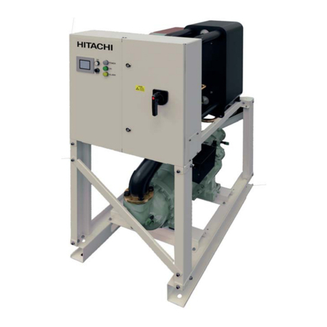
Hitachi SAMURAI Series User manual

SAMURAI SERIES
AIR COOLED WATER CHILLERS AND
AIR TO WATER HEAT PUMP
-MODULAR-R134a-SCREW TYPE-
RCME-(40-70)AH1
RCME-(080-210)/(2-3)AH1
Service Manual
RHME-(40-70)AH1
RHME-(080-210)/(2-3)AH1


SMGB0082 rev.1 - 07/2015
III
General Index
General index
1. General information................................................................................................... 1
1.1 General notes..........................................................................................................................................2
1.2 Safety and applied symbols .................................................................................................................... 3
1.3 Product guide ..........................................................................................................................................4
1.3.1 Classication of water chiller models .............................................................................................................. 4
1.3.2 Product guide: Air cooled water chillers (RCME) ............................................................................................ 5
1.3.3 Product guide: Air to water heat pump (RHME) .............................................................................................. 6
2. Control Functions ...................................................................................................... 7
2.1 Control functions on the module.............................................................................................................. 8
2.1.1 Water control ..................................................................................................................................................11
2.1.2 Water temperature control............................................................................................................................. 12
2.1.3 Compressor Control ...................................................................................................................................... 15
2.1.4 Control for recovery from power interruption (Option)................................................................................... 17
2.1.5 Prevention of simultaneous startup ............................................................................................................... 18
2.1.6 Reverse prevention control ........................................................................................................................... 18
2.1.7 Anti-Freezing Control for Winter .................................................................................................................... 19
2.1.8 Control for prevention of wrong operation and wrong settings...................................................................... 22
2.1.9 Demand control ............................................................................................................................................. 22
2.1.10 Forced load up capacity control from external signal .................................................................................. 25
2.1.11 2-temperature setting function..................................................................................................................... 26
2.1.12 External thermo operation from external contact ........................................................................................ 27
2.1.13 Water Temperature of the Control Target .................................................................................................... 29
2.1.14 Operation from DC24V contact input .......................................................................................................... 30
2.1.15 Attachment of snowfall switch (Forced fan operation)................................................................................. 35
2.1.16 Silence priority mode (Night shift) (Only in cooling operation) .................................................................... 36
2.1.17 Thermo OFF function selection ................................................................................................................... 37
2.1.18 Selection of enabling/disabling of alarm release by means of remote stop ................................................ 38
2.1.19 Limitation setting for pump feedback waiting time....................................................................................... 39
2.1.20 Inlet water temperature thermo OFF function ............................................................................................. 40
2.1.21 Intermitent fan operation ............................................................................................................................. 41
2.1.22 Switch for conrmation of high pressure cut. (Cooling operation)............................................................... 42
2.1.23 Switch for conrmation of low pressure cut. (Cooling operation). ............................................................... 43
2.1.24 Switch for conrmation of low pressure cut. (Heating operation) ................................................................ 43
2.2 Control of the cooling cycle ................................................................................................................... 44
2.2.1 Compressor Control ...................................................................................................................................... 44
2.2.2 Fan Control.................................................................................................................................................... 45
2.2.3 Expansion Valve Control ............................................................................................................................... 46

SMGB0082 rev.1 - 07/2015
IV
General Index
2.2.4 Overcurrent protection control....................................................................................................................... 48
2.2.5 Defrosting (only for air-cooled heat pump systems (RHME))........................................................................ 49
2.3 Control of Master/Slave group............................................................................................................... 52
2.3.1 Summary of control of Master/Slave group ................................................................................................... 52
2.3.2 Setting method .............................................................................................................................................. 52
2.3.3 Operation method.......................................................................................................................................... 53
2.3.4 Other functions of the control of Master/Slave group .................................................................................... 56
2.3.5 Setting items.................................................................................................................................................. 58
2.3.6 Method for setting and conrmation of operation conditions through the LCD screen.................................. 59
2.4 Run operation........................................................................................................................................61
2.4.1 Setting of switches on the setting PCB ......................................................................................................... 61
2.4.2 Operation control of the module .................................................................................................................... 62
2.5 Time chart .............................................................................................................................................63
3. Servicing................................................................................................................... 67
3.1 LCD display for Service Menu............................................................................................................... 69
3.2 General notes........................................................................................................................................77
3.3 Access inside the module for servicing ................................................................................................. 77
3.4 Removing covers...................................................................................................................................78
3.4.1 Unit description.............................................................................................................................................. 78
3.4.2 Panels on the left (2 panels) or right side (2 panels)..................................................................................... 79
3.4.3 Front cover (E-Box - compressor side) ......................................................................................................... 79
3.4.4 Front cover (Hex lower cover) ....................................................................................................................... 80
3.4.5 Rear cover (water connection side)............................................................................................................... 80
3.4.6 Water pipes support ...................................................................................................................................... 81
3.4.7 Protection net (Air cooler grille) ..................................................................................................................... 82
3.5 Cycle components.................................................................................................................................83
3.5.1 Compressor removal ..................................................................................................................................... 83
3.5.2 Overhaul work ............................................................................................................................................... 85
3.5.3 Recovering the refrigerant ............................................................................................................................ 86
3.5.4 Replacement of the Brazed plate heat exchanger ........................................................................................ 87
3.5.5 Replacement of the expansion valve ............................................................................................................ 89
3.5.6 Replacement of the check valve ................................................................................................................... 90
3.5.7 Filter drier ...................................................................................................................................................... 91
3.5.8 Replacement of the stop valve (with check joint) .......................................................................................... 92
3.5.9 Replacement of the high pressure switch (PSH)........................................................................................... 92
3.5.10 Replacement of the pressure sensor (Pd)................................................................................................... 92
3.5.11 Replacement of the pressure sensor (Ps) ................................................................................................... 92
3.5.12 Replacement of the pressure sensor (PSW)............................................................................................... 93

SMGB0082 rev.1 - 07/2015
V
General Index
3.5.13 Replacement of the pressure relief valve .................................................................................................... 93
3.5.14 Replacement of the sight glass ................................................................................................................... 93
3.5.15 Replacement of the crankcase heater (CH) ................................................................................................ 93
3.5.16 Replacement of the stop valve (x3)............................................................................................................. 94
3.5.17 Replacement of the thermistor (Suction, THMs) ......................................................................................... 94
3.5.18 Replacement of the thermistor (Discharge, THMd)..................................................................................... 95
3.5.19 Replacement of the thermistor (x2) (Evaporation, THMr2) ......................................................................... 95
3.5.20 Replacement of the thermistor (Cooler water inlet, THMwi)........................................................................ 96
3.5.21 Thermistor (Cooler water outlet, THMwo2) ................................................................................................. 96
3.5.22 Thermistor (Cooler water outlet, THMwo) ................................................................................................... 97
3.5.23 Replacement of the solenoid valves (SVa, SVb, SVc) ................................................................................ 97
3.5.24 Replacement of the water inlet pipe purge.................................................................................................. 97
3.5.25 Removing the differential pressure device (optional) .................................................................................. 98
3.6 Electrical components ...........................................................................................................................99
3.6.1 Replacement of the electrical box assy......................................................................................................... 99
3.6.2 Open electrical box doors............................................................................................................................ 100
3.6.3 Replacement of lamps and push buttons .................................................................................................... 101
Removal of the PCB’s ........................................................................................................................................... 102
3.6.4 Removal of the LCD screen ........................................................................................................................ 104
3.6.5 Transformer (TF1) ....................................................................................................................................... 106
3.6.6 Transformers (TF2, TF3, TF4)..................................................................................................................... 106
3.6.7 Overcurrent relay (ORC) ............................................................................................................................. 107
3.6.8 Contactors (CMC, CMCD, CMCS) .............................................................................................................. 107
3.6.9 Fuses (EF1, EF2, EF3. EFR, EFS, EFT) .................................................................................................... 108
3.6.10 Fuses (PFC) .............................................................................................................................................. 108
3.6.11 Relays........................................................................................................................................................ 109
3.6.12 Main Switch ................................................................................................................................................110
3.6.13 Capacitors ..................................................................................................................................................110
4. Troubleshooting..................................................................................................... 111
4.1 Inspection of power source and connections ...................................................................................... 112
4.2 Inspection of PCB................................................................................................................................ 113
4.3 Conrmation of operating value of protection devices and automatic operation devices ................... 113
4.4 Process of abnormality of Inverter for Fan .......................................................................................... 114
4.5 Protection control function................................................................................................................... 116
4.6 Caution indication................................................................................................................................ 117
4.7 Summary of fault diagnosis................................................................................................................. 118
4.8 Method for judgement of failure of Fan Module (Inverter)...................................................................120
4.8.2 Emergency operation method in case of Fan Module failure ...................................................................... 121

SMGB0082 rev.1 - 07/2015
VI
General Index
4.9 Method for fault diagnosis ................................................................................................................... 122
4.10 Troubleshooting by alarm code ........................................................................................................... 123
4.11 Analysis and countermeasure of abnormalities...................................................................................153
4.12 Thermistor characteristics ................................................................................................................... 160
4.12.1 Thermistor temperature characteristics (All temperature except ambient and discharge gas) ................. 160
4.12.2 Thermistor temperature characteristics for ambient temperature ............................................................. 160
4.12.3 Thermistor temperature characteristics for discharge gas temperature.................................................... 160
4.13 Pressure sensor characteristics .......................................................................................................... 161
4.13.1 High-pressure sensor ................................................................................................................................ 161
4.13.2 Low-pressure sensor................................................................................................................................. 161
4.14 Procedures for trouble.........................................................................................................................162

1. General information
SMGB0082 rev.1 - 07/2015
1
1
1. General information
Index
1.1 General notes..........................................................................................................................................2
1.2 Safety and applied symbols .................................................................................................................... 3
1.3 Product guide ..........................................................................................................................................4
1.3.1 Classication of water chiller models .............................................................................................................. 4
1.3.2 Product guide: Air cooled water chillers (RCME) ............................................................................................ 5
1.3.3 Product guide: Air to water heat pump (RHME) .............................................................................................. 6

1. General information
General notes
SMGB0082 rev.1 - 07/2015
2
1.1 General notes
© Copyright 2014 HITACHI Air Conditioning Products Europe, S.A.U. – All rights reserved.
No part of this publication may be reproduced, copied, led or transmitted in any shape or form without the permission of
HITACHI Air Conditioning Products Europe, S.A.U.
Within the policy of continuous improvement of its products, HITACHI Air Conditioning Products Europe, S.A.U. reserves
the right to make changes at any time without prior notication and without being compelled to introducing them into
products subsequently sold. This document may therefore have been subject to amendments during the life of the product.
HITACHI makes every effort to offer correct, up-to-date documentation. Despite this, printing errors cannot be controlled by
HITACHI and are not its responsibility.
As a result, some of the images or data used to illustrate this document may not refer to specic models. No claims will be
accepted based on the data, illustrations and descriptions included in this document.
No type of modication must be made to the equipment without prior, written authorisation from the manufacturer.
HITACHI pursues a policy of continuing improvement in design and performance of products. The right is therefore reserved
to vary specications without notice.
HITACHI cannot anticipate every possible circumstance that might involve a potential hazard.
No part of this document may be reproduced without written permission.
If you have any questions, contact your service contractor of HITACHI.
Check and make sure that the explanations of each part of this document correspond to your water chiller model.
Refer to the models codication to conrm the main characteristics of your system.
Signal words (DANGER, CAUTION and NOTE) are used to identify levels of hazard seriousness. Denitions for identifying
hazard levels are provided below with their respective signal words.
It is assumed that this unit will be operated and serviced by English speaking people. If this is not the case, the customer
should add safety, caution and operating signs in the native language of the personal.

1. General information
Safety and applied symbols
SMGB0082 rev.1 - 07/2015
3
1
1.2 Safety and applied symbols
During normal system design work or unit installation, greater attention must be paid in certain situations requiring particular
care in order to avoid damage to the unit, the installation or the building or property.
Situations that jeopardise the safety of those in the surrounding area or that put the unit itself at risk will be clearly indicated
in this manual.
To indicate these situations, a series of special symbols will be used to clearly identify these situations.
Pay close attention to these symbols and to the messages following them, as your safety and that of others depends on it.
DANGER
• The text following this symbol contains information and instructions relating directly to your safety and
physical wellbeing.
• Not taking these instructions into account could lead to serious, very serious or even fatal injuries to you and
others in the proximity of the unit.
• Hazards or unsafe practices which could result severe personal injury or death.
In the texts following the danger symbol you can also nd information on safe procedures during unit installation.
CAUTION
• The text following this symbol contains information and instructions relating directly to your safety and physical wellbeing.
• Not taking these instructions into account could lead to minor injuries to you and others in the proximities of the unit.
• Not taking these instructions into account could lead to unit damage.
In the texts following the caution symbol you can also nd information on safe procedures during unit installation.
NOTE
• The text following this symbol contains information or instructions that may be of use or that require a more thorough
explanation.
• Instructions regarding inspections to be made on unit parts or systems may also be included.

1. General information
Product guide
SMGB0082 rev.1 - 07/2015
4
1.3 Product guide
1.3.1 Classication of water chiller models
Basic modules
Unit type (Modular water chiller): RCM: Air cooled water chiller
RHM: Air to water heat pump
E = Made in Europe
Position-separating hyphen (xed)
Capacity (HP): 40, 50, 60, 70
A = Air cooled
H = R134a refrigerant
Series 1
R(C/H)M E – XX A H1
Factory built modules combinations
Unit type (Modular water chiller): RCM Air cooled water chiller
RHM Air to water heat pump
E = Made in Europe
Position-separating hyphen (xed)
Total capacity (HP): 080, 090, 100, 110, 120, 130, 140, 150, 160, 170, 180, 190, 200, 210
Position-separating slash (xed)
Nº of modules: 2, 3
A = Air cooled
H = R134a refrigerant
Series 1
R(C/H)M E – XXX /X A H1

1. General information
Product guide
SMGB0082 rev.1 - 07/2015
5
1
1.3.2 Product guide: Air cooled water chillers (RCME)
Basic modules
3N~ 400V 50Hz
Unit Code
RCME-40AH1 8E041341
RCME-50AH1 8E051341
RCME-60AH1 8E061341
RCME-70AH1 8E071341
Factory built modules combinations
3N~ 400V 50Hz
Modules of 2 units Code Modules of 3 units Code
RCME-080/2AH1 8E080201
RCME-090/2AH1 8E090201
RCME-100/2AH1 8E100201
RCME-110/2AH1 8E110201
RCME-120/2AH1 8E120201
RCME-130/2AH1 8E130201
RCME-140/2AH1 8E140201
RCME-150/3AH1 8E150301
RCME-160/3AH1 8E160301
RCME-170/3AH1 8E170301
RCME-180/3AH1 8E180301
RCME-190/3AH1 8E190301
RCME-200/3AH1 8E200301
RCME-210/3AH1 8E210301

1.3.3 Product guide: Air to water heat pump (RHME)
Basic modules
3N~ 400V 50Hz
Unit Code
RHME-40AH1 9E041341
RHME-50AH1 9E051341
RHME-60AH1 9E061341
RHME-70AH1 9E071341
Factory built modules combinations
3N~ 400V 50Hz
Modules of 2 units Code Modules of 3 units Code
RHME-080/2AH1 9E080201
RHME-090/2AH1 9E090201
RHME-100/2AH1 9E100201
RHME-110/2AH1 9E110201
RHME-120/2AH1 9E120201
RHME-130/2AH1 9E130201
RHME-140/2AH1 9E140201
RHME-150/3AH1 9E150301
RHME-160/3AH1 9E160301
RHME-170/3AH1 9E170301
RHME-180/3AH1 9E180301
RHME-190/3AH1 9E190301
RHME-200/3AH1 9E200301
RHME-210/3AH1 9E210301

2. Control Functions
SMGB0082 rev.1 - 07/2015
7
2
2. Control Functions
Index
2.1 Control functions on the module..............................................................................................................8
2.1.1 Water control ..................................................................................................................................................11
2.1.2 Water temperature control............................................................................................................................. 12
2.1.3 Compressor Control ...................................................................................................................................... 15
2.1.4 Control for recovery from power interruption (Option)................................................................................... 17
2.1.5 Prevention of simultaneous startup ............................................................................................................... 18
2.1.6 Reverse prevention control ........................................................................................................................... 18
2.1.7 Anti-Freezing Control for Winter .................................................................................................................... 19
2.1.8 Control for prevention of wrong operation and wrong settings...................................................................... 22
2.1.9 Demand control ............................................................................................................................................. 22
2.1.10 Forced load up capacity control from external signal .................................................................................. 25
2.1.11 2-temperature setting function..................................................................................................................... 26
2.1.12 External thermo operation from external contact ........................................................................................ 27
2.1.13 Water Temperature of the Control Target .................................................................................................... 29
2.1.14 Operation from DC24V contact input .......................................................................................................... 30
2.1.15 Attachment of snowfall switch (Forced fan operation)................................................................................. 35
2.1.16 Silence priority mode (Night shift) (Only in cooling operation) .................................................................... 36
2.1.17 Thermo OFF function selection ................................................................................................................... 37
2.1.18 Selection of enabling/disabling of alarm release by means of remote stop ................................................ 38
2.1.19 Limitation setting for pump feedback waiting time....................................................................................... 39
2.1.20 Inlet water temperature thermo OFF function ............................................................................................. 40
2.1.21 Intermitent fan operation ............................................................................................................................. 41
2.1.22 Switch for conrmation of high pressure cut. (Cooling operation)............................................................... 42
2.1.23 Switch for conrmation of low pressure cut. (Cooling operation). ............................................................... 43
2.1.24 Switch for conrmation of low pressure cut. (Heating operation) ................................................................ 43
2.2 Control of the cooling cycle ................................................................................................................... 44
2.2.1 Compressor Control ...................................................................................................................................... 44
2.2.2 Fan Control.................................................................................................................................................... 45
2.2.3 Expansion Valve Control ............................................................................................................................... 46
2.2.4 Overcurrent protection control....................................................................................................................... 48
2.2.5 Defrosting (only for air-cooled heat pump systems (RHME))........................................................................ 49
2.3 Control of Master/Slave group............................................................................................................... 52
2.3.1 Summary of control of Master/Slave group ................................................................................................... 52
2.3.2 Setting method .............................................................................................................................................. 52
2.3.3 Operation method.......................................................................................................................................... 53
2.3.4 Other functions of the control of Master/Slave group .................................................................................... 56
2.3.5 Setting items.................................................................................................................................................. 58
2.3.6 Method for setting and conrmation of operation conditions through the LCD screen.................................. 59
2.4 Run operation........................................................................................................................................61
2.4.1 Setting of switches on the setting PCB ......................................................................................................... 61
2.4.2 Operation control of the module .................................................................................................................... 62
2.5 Time chart .............................................................................................................................................63

2. Control Functions
Control functions on the module
SMGB0082 rev.1 - 07/2015
8
2.1 Control functions on the module
List of the main control functions
Item Description
Automatic water
temperature control
1 Slide valve control
The outlet water temperature of the chiller unit is detected with a thermistor, and the stroke of slide valve is
controlled continuously by time-sharing.
Setting Temperature
Neutral Zone
Load down area
(Hold)
Load up area
Example of cooling operation: Outlet Water Temperature
Capacity control range: 100~25%, Stop.
2 Thermo ON-OFF control
When operation load becomes light, outlet water temperature falls below the "Stop temperature range" against
the lower limit temperature in neutral zone (in the case of cooling operation; increase in the case of heating
operation). By doing so, the compressor stops (Thermo OFF).
The settings of stop temperature range can be changed locally between 0.5 and 2.0ºC (in 0.5ºC steps).
Example of cooling operation:
Lower limit in
neutral zone
Stop temperature range
Outlet water temperature
Thermo OFF
Also, in case that water temperature increases above "Recovery temperature range" against inlet temperature
when Thermo ON is set (in the case of cooling operation; decrease in the case of heating operation), the
compressor starts (Themo ON). (However, there is a time guard with a minimum of 3 minutes )
It is possible to change the settings of recovery temperature range, but please take into account that the water
volume necessary to maintain the frequency of compressor run/stop will be different.
Compressor Control
Once that "Compressor delay time" has passed after pump startup, compressor starts up with
Υ
-Δ control,
performs startup unload control during 60 seconds, and then shifts to capacity control.
The settings of Compressor delay time can be changed in the range between 30 seconds and 10 minutes (in
30 second steps).
Please set a delay time adjusted to the characteristics of the installation, to prevent compressor startup until a
sufcient ow of cold water can be ensured after pump startup. Default: 30 seconds.
Recovery from
momentary power
failure
Compressor is temporarily stopped when a momentary power failure (drop of more than 20% of power source
voltage detected for a period between 13 milliseconds and 2 seconds) occurs, and it is automatically restarted
after time guard time has passed. Also, momentary power failure detection signal is output during 10 seconds
upon detection of momentary power failure.
Automatic recovery
from power
interruption
(Option)
It is possible to restart automatically after recovery from a power interruption (or power source OFF) exceeding
2 seconds.
NOTE
• It returns to the state immediately before the occurrence of power interruption. In case that the unit was
stopped before power interruption, it remains stopped.
• Since this function is optional, it is necessary to make the settings for the enabling of this function at the time
of local installation.
• Since there is the possibility that operation starts abruptly upon power ON, given the circumstances at the
time of power OFF, please be careful enough when enabling this function.
Reverse prevention The status of the three phases of power input is monitored, to prevent operation in reverse and open phase.

2. Control Functions
Control functions on the module
SMGB0082 rev.1 - 07/2015
9
2
Item Description
Anti-freezing for
winter
(Automatic pump
operation)
In order to prevent freezing caused by a decrease of water temperature in winter or under other low ambient
temperature conditions, pump operation order is output automatically.
NOTE
Starting conditions can be selected locally from the 3 types below.
• Water temperature under 15ºC (mainly for systems where the total pump head from the chiller unit to the load
side is supported by a common pump. It protects the entire chiller and load side equipment)
• Water temperature under 5ºC (mainly for systems where the head of chiller unit side and of load side are
supported by separate pumps). It only protects the chiller unit side)
• Disable function: When selecting "Disable function", other freeze prevention measures, such as extraction of
water in winter or winding a heater around the heat exchanger Mare necessary. Refrigerant may leak if the
water side heat exchanger freezes.
Incorrect operation
prevention
It is not possible to switch between remote and main unit control, and between cooling and heating, during
operation of the chiller unit. An alarm is output with respect to such incorrect operation, and to wrong DIP switch
settings. Also, an alarm is output to prevent danger, in case that an operation order is input from a remote when
settings are for main unit control.
Demand control
Compressor operation can be limited by external signal input.
Forced thermo OFF: Compressor is stopped forcedly during external signal input.
Current limit function: Operation capacity is limited to make the running current lower than the setting value of
current limit control, during external signal input. Limit value can be changed by local settings.
Forced load-up: Load-up output is conducted forcedly during external signal input.
Capacity hold: Capacity control is ignored forcedly during external signal input.
2 temperature
setting
Cooling operation and heating operation have 2 setting temperatures each, and it is possible to select which
setting temperature is valid by external signal input. In case of operating with a different extraction temperature,
such as heat storage or air conditioning, it is not necessary to change the setting temperature of the main
chiller unit.
Forced load up from
external contact
Forced load up is conducted during outdoor order (non-voltage a contact) input.
It is possible to select whether "the pump shall stop" or "the pump can be kept working" in the event of a thermo
OFF, when thermo OFF judgement at the main unit is enabled.
(This function cannot be used when the function to control the number of units is used )
Information about
overhaul period
Compressor operation time for preventive maintenance is monitored, and when it reaches the overhaul period,
the "Overhaul mark" is shown on the LCD screen.
Disabling of remote
stop alarm clear
(Option)
It is possible to disable the release of alarms by remote stop order input.
NOTE
• Normally, alarms can be released by stop control from either remote or the main unit.
• Since this function is optional, it is necessary to make the settings for the enabling of this function at the time
of local installation.
Limit of waiting time
for pump feedback
(Option)
It is possible to determine pump interlock abnormality and output an alarm in case that no pump feedback
signal is input after a certain amount of time has passed upon startup of the chiller unit.
This time can be changed by local settings, between 1 and 30 minutes (in 1 minute steps).
NOTE
The default feedback waiting time is "unlimited".
Thermo OFF
judgement delay
(Option)
It is possible to delay the judgement time of thermo OFF to avoid immediate thermo OFF when water
temperature reached thermo OFF judgement value due to uctuations in the amount of cold water ow, caused
by momentary variations in load or the activation of valves, etc.
NOTE
• Since this function is optional, it is necessary to make the settings for the enabling of this function at the time
of local installation.
• Thermo OFF is produced when reaching operation limit temperature, even if being in judgement time.

2. Control Functions
Control functions on the module
SMGB0082 rev.1 - 07/2015
10
Item Description
Thermo OFF
judgement due to
inlet temperature
It is possible to determine thermo OFF from the inlet water temperature (return temperature from load) of the
chiller unit. It is possible to change the settings of thermo OFF temperature.
NOTE
Since this function is optional, it is necessary to make the settings for the enabling of this function at the time of
local installation.
Forced fan
operation
It is possible to force fan operation by external signal input.
It is enabled as a function to prevent the accumulation of snow while the chiller unit is stopped.
Intermitent fan
operation
Intermitent operation (15 seconds run, 3 minutes stop) is performed automatically when outdoor temperature is
lower than 4ºC, in order to prevent freezing of fan due to the accumulation of snow when the fan is stopped in
winter.
It is possible to select the disabling of this function as well. Default: Enabled.
Preservation of
alarm data
When an alarm occurs, the contents of the alarm, as well as the date and time of occurrence are recorded.
The most recent 10 cases are stored, and then they are deleted from the oldest. Also, for the most recent 3
cases, the data of each sensor (right before occurrence, 10 seconds before and 20 seconds before) as well as
data regarding each setting and operation conditions are stored, and it is possible to check them later on. This
supports the early identication of the causes of alarm occurrence.
Water Temp Set Setting is possible in 0.5ºC units.
Display
Main unit side
LCD device: Displays the status of the chiller unit (Run, stop, contents of alarm, operating pressure and
temperature, etc.)
7-Segment (for backup of the LCD): Displays the status of the unit and content of alarms with individual codes
Pilot lamps: Lit on for power source: white, run: red, alarm: orange
Remote display
Outputs operation of the chiller unit, cool/heat mode, pump operation, alarm, warning and defrosting
Control of Master/
Slave group
(Module Control)
(Option)
When installing multiple units, operation as one entire heat system is possible by connecting each chiller unit
through H-LINK.
It is possible to connect a maximum of 8 units to one group.
NOTE
• Since this function is optional, it is necessary to make the settings for the enabling of this function at the time
of local installation.
• An exclusive controller is not required, but optional parts may become necessary depending on the structure
of the local system.

2. Control Functions
Control functions on the module
SMGB0082 rev.1 - 07/2015
11
2
2.1.1 Water control
Outlet water temperature of Chiller Unit is detected by Thermistor, and based on this value, compressor ON/OFF and the
most suitable capacity is determined. Following shown the continuous capacity control and change of water temperature.
9ºC
8ºC
7ºC
6ºC
5ºC
(0.5~5.0ºC)
(0.5~2.0ºC)
(1.0~3.0ºC)
T4
Δ
Tsc:7ºC
T1: 1ºC
T2: 2ºC
T3: 2ºC
T4: 1ºC
Δ
Δ
Δ
Δ
Tsc (setting t.)
T1Δ
T2Δ
T3Δ
Tsc+ T2/3+ T4ΔΔ
Tsc+ T2/3Δ
Tsc- T2/3Δ
Tsc- T2/3- T1ΔΔ
T3Δ
T4Δ
T1Δ
(1.0~4.0ºC)
T2Δ
Outlet
temperature Inlet
temperature
Stop
(Thermo off)
Start
(re-start)
Memorizes the inlet temperature
at Thermo-OFF and re-start at
∆T2
Load up I zone
Load up II zone
Load Down zone
Thermo-off zone
Load up I
status
Load up II
status
Neutral status Load-down status Stop
status
Load up II
status
Neutral
status
Neutral status
Neutral zone
Starting setting
(example)
Method of outlet temperature detection
1 Load-up I control at over 9°C (The capacity is changed a lot in order to approximate the target temp. quickly)
2 Load-up II control at 8~9°C (The capacity is changed moderately)
3 In neutral zone (6~8°C), load is balanced and performance is not changed.
4 Under neutral zone (below 6°C) load-down control is performed and performance is decreased.
5 Stop temp: Compressor is stopped at 5°C. The inlet temp of that time is saved.
6 When inlet temp becomes 2°C higher than that of at stop, re-start signal is output and unit is re-started after at least 3
min guard.

2. Control Functions
Control functions on the module
SMGB0082 rev.1 - 07/2015
12
2.1.2 Water temperature control
1 Automatic temperature adjustment
Compressor run/stop and capacity control are performed by detecting water temperature of the chiller unit with
thermistors.
Item
Model
Water Temp Set ON/OFF Temperature Difference Stop Temperature Range
Available range
(ºC) Step (ºC) Setting range
(ºC) Step (ºC)
Air-cooled
cooling only 4 ~ 30
0.5
0~4
Default: 2
1
0.5~2.0
Default: 1.0
0.5
Air cooled heat
pump
Cooling 4 ~ 30
Heating 35 ~ 60
NOTE
• Return temperature range indicates the amount of change in inlet water temperature of the chiller unit to determine
thermo ON after thermo OFF. (In the case of cooling: amount of temperature increase; in the case of heating: amount
of temperature decrease)
• It is possible to change settings locally depending on usage purpose, but since the necessary volume of water will
change, please change the settings only upon conrmation of the amount of the retained volume of water in the entire
local system.
Output Cycle Load up I
Output time
Load up II
Output time
Load down
Output time
Setting range
(Seconds)
10~120
(Default: 30)
10~120
(Default: 10)
2~120
(Default: 2)
2~120
(Default: 2)
Step
(Seconds) 10 1 1 1
Neutral Zone Range Load up II range
Setting range (ºC) 1~5 (Default: 2) 1~3 (Default: 1)
Step (ºC) 1 1
NOTE
• Return temperature range indicates the amount of change in inlet water temperature of the chiller unit to determine
thermo ON after thermo OFF. (In the case of cooling: amount of temperature increase; in the case of heating: amount
of temperature decrease).
• It is possible to change settings locally depending on usage purpose, but since the necessary volume of water will
change, please change the settings only upon conrmation of the amount of the retained volume of water in the entire
local system.
Other manuals for SAMURAI Series
3
This manual suits for next models
2
Table of contents
Other Hitachi Chiller manuals
Popular Chiller manuals by other brands

Daikin
Daikin EWAD E-SS Series Installation, operation and maintenance manual

Carrier
Carrier 30AJ Installation, operation and maintenance manual

Carrier
Carrier 19DG Start up & operation manual

CIAT
CIAT AquaCIAT LD Series User brochure

Polar Refrigeration
Polar Refrigeration CB932 instruction manual

York
York YCWJ45EE0 Installation operation & maintenance