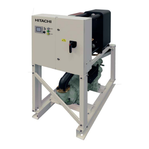
Hitachi HC-A32MB User manual

INSTALLATION AND OPERATION MANUAL
MANUAL DE INSTALACIÓN Y FUNCIONAMIENTO
INSTALLATIONS- UND BETRIEBSHANDBUCH
MANUEL D’INSTALLATION ET DE FUNCTIONNEMENT
MANUALE D’INSTALLAZIONE E D’USO
MANUAL DE INSTALAÇÃO E DE FUNCIONAMENTO
BRUGER- OG MONTERINGSVEJLEDNING
INSTALLATIE- EN BEDIENINGSHANDLEIDING
INSTALLATIONS- OCH DRIFTHANDBOK
ΕΓΧΕΙΡΙΔΙΟ ΕΓΚΑΤΑΣΤΑΣΗΣ ΚΑΙ ΛΕΙΤΟΥΡΓΙΑΣ
HC-A32MB
PMML0191A rev. 2 - 05/2013 Printed in Spain
PMML0191A rev. 2 - 05/2013 HC-A32MB - Operation and installation manual


Specications in this manual are subject to change without notice in order that HITACHI may
bring the latest innovations to their customers.
Whilst every effort is made to ensure that all specications are correct, printing errors are beyond
Hitachi’s control; Hitachi cannot be held responsible for these errors.
Las especicaciones de este manual están sujetas a cambios sin previo aviso a n de que
HITACHI pueda ofrecer las últimas innovaciones a sus clientes.
A pesar de que se hacen todos los esfuerzos posibles para asegurarse de que las
especicaciones sean correctas, los errores de impresión están fuera del control de HITACHI, a
quien no se hará responsable de ellos.
Bei den technischen Angaben in diesem Handbuch sind Änderungen vorbehalten, damit
HITACHI seinen Kunden die jeweils neuesten Innovationen präsentieren kann.
Sämtliche Anstrengungen wurden unternommen, um sicherzustellen, dass alle technischen
Informationen ohne Fehler veröffentlicht worden sind. Für Druckfehler kann HITACHI jedoch
keine Verantwortung übernehmen, da sie außerhalb ihrer Kontrolle liegen.
Les caractéristiques publiées dans ce manuel peuvent être modiées sans préavis, HITACHI
souhaitant pouvoir toujours offrir à ses clients les dernières innovations.
Bien que tous les efforts sont faits pour assurer l’exactitude des caractéristiques, les erreurs
d’impression sont hors du contrôle de HITACHI qui ne pourrait en être tenu responsable.
Le speciche di questo manuale sono soggette a modica senza preavviso afnché HITACHI
possa offrire ai propri clienti le ultime novità.
Sebbene sia stata posta la massima cura nel garantire la correttezza dei dati, HITACHI non è
responsabile per eventuali errori di stampa che esulano dal proprio controllo.
As especicações apresentadas neste manual estão sujeitas a alterações sem aviso prévio, de
modo a que a HITACHI possa oferecer aos seus clientes, da forma mais expedita possível, as
inovações mais recentes.
Apesar de serem feitos todos os esforços para assegurar que todas as especicações
apresentadas são correctas, quaisquer erros de impressão estão fora do controlo da HITACHI,
que não pode ser responsabilizada por estes erros eventuais.
Specikationerne i denne vejledning kan ændres uden varsel, for at HITACHI kan bringe de
nyeste innovationer ud til kunderne.
På trods af alle anstrengelser for at sikre at alle specikationerne er korrekte, har Hitachi ikke
kontrol over trykfejl, og Hitachi kan ikke holdes ansvarlig herfor.
De specicaties in deze handleiding kunnen worden gewijzigd zonder verdere kennisgeving
zodat HITACHI zijn klanten kan voorzien van de nieuwste innovaties.
Iedere poging wordt ondernomen om te zorgen dat alle specicaties juist zijn. Voorkomende
drukfouten kunnen echter niet door Hitachi worden gecontroleerd, waardoor Hitachi niet
aansprakelijk kan worden gesteld voor deze fouten.
Specikationerna i den här handboken kan ändras utan föregående meddelande för att HITACHI
ska kunna leverera de senaste innovationerna till kunderna.
Vi på Hitachi gör allt vi kan för att se till att alla specikationer stämmer, men vi har ingen kontroll
över tryckfel och kan därför inte hållas ansvariga för den typen av fel.
Οι προδιαγραφές του εγχειριδίου μπορούν να αλλάξουν χωρίς προειδοποίηση, προκειμένου η
HITACHI να παρέχει τις τελευταίες καινοτομίες στους πελάτες της.
Αν και έχει γίνει κάθε προσπάθεια προκειμένου να εξασφαλιστεί ότι οι προδιαγραφές είναι
σωστές, η Hitachi δεν μπορεί να ελέγξει τα τυπογραφικά λάθη και, ως εκ τούτου, δεν φέρει καμία
ευθύνη για αυτά τα λάθη.

¬ATTENTION:
This product shall not be mixed with general house waste at the end of its life and it shall be retired according to the
appropriated local or national regulations in a environmentally correct way.
Contact to the corresponding authorities for more information.
¬ATENCIÓN:
Éste producto no se debe eliminar con la basura doméstica al final de su vida útil y se debe desechar de manera
respetuosa con el medio ambiente de acuerdo con los reglamentos locales o nacionales aplicables.
Para obtener más información, póngase en contacto con las autoridades competentes.
¬ACHTUNG:
Dass Ihr Produkt am Ende seiner Betriebsdauer nicht in den allgemeinen Hausmüll geworfen werden darf, sondern
entsprechend den geltenden örtlichen und nationalen Bestimmungen auf umweltfreundliche Weise entsorgt werden muss.
Für weitere Informationen setzen Sie sich bitte mit den entsprechenden Behörden in Verbindung.
¬ATTENTION:
Ne doit pas être mélangé aux ordures ménagères ordinaires à la fin de sa vie utile et qu’il doit être éliminé conformément à
la réglementation locale ou nationale, dans le plus strict respect de l’environnement.
Pour de plus amples informations, contactez les autorités compétentes.
¬ATTENZIONE:
Indicazioni per il corretto smaltimento del prodotto ai sensi della Direttiva Europea 2002/96/EC e Dlgs 25 luglio 2005 n.151
Il simbolo del cassonetto barrato riportato sull' apparecchiatura indica che il prodotto alla fine della propria vita utile deve
essere raccolto separatamente dagli altri rifiuti.
L'utente dovrà, pertanto, conferire l'apparecchiatura giunta a fine vita agli idonei centri di raccolta differenziata dei rifiuti
elettronici ed elettrotecnici, oppure riconsegnarla al rivenditore al momento dell' acquisto di una nuova apparecchiatura di
tipo equivalente.
L'adeguata raccolta differenziata delle apparecchiature dismesse, per il loro avvio al riciclaggio, al trattamento ed allo
smaltimento ambientalmente compatibile, contribuisce ad evitare possibili effetti negativi sull' ambiente e sulla salute e
favorisce il riciclo dei materiali di cui è composta l' apparecchiatura.
Vogliate contattare l' installatore, il rivenditore, o le autorità locali per ulteriori informazioni.
Lo smaltimento abusivo del prodotto da parte dell’utente può comportare l’applicazione delle sanzioni amministrative di cui
all’articolo 50 e seguenti del D.Lgs. n. 22/1997.
¬ATENÇÃO:
O seu produto não deve ser misturado com os desperdícios domésticos de carácter geral no final da sua duração e que
deve ser eliminado de acordo com os regulamentos locais ou nacionais adequados de uma forma correcta para o meio
ambiente.
Contacte as autoridades correspondentes para obter mais informações.
¬BEMÆRK:
At produktet ikke må smides ud sammen med almindeligt husholdningsaffald, men skal bortskaffes i overensstemmelse
med de gældende lokale eller nationale regler på en miljømæssig korrekt måde.
Kontakt de pågældende myndigheder for at få yderligere oplysninger.
¬ATTENTIE:
Dit houdt in dat uw product niet wordt gemengd met gewoon huisvuil wanneer u het weg doet en dat het wordt gescheiden
op een milieuvriendelijke manier volgens de geldige plaatselijke en landelijke reguleringen.
Neem contact op met de betreffende overheidsdienst voor meer informatie.
¬OBS!:
Det innebär att produkten inte ska slängas tillsammans med vanligt hushållsavfall utan kasseras på ett miljövänligt sätt i
enlighet med gällande lokal eller nationell lagstiftning.
Ta kontakt med ansvarig myndighet om du vill ha mer information.
¬ȆȇȅȈȅȋǾ:
ȈȘȝĮȓȞİȚ ȩIJȚ IJȠ ʌȡȠȧȩȞ įİȞ șĮ ʌȡȑʌİȚ ȞĮ ĮȞĮȝȚȤșİȓ ȝİ IJĮ įȚȐijȠȡĮ ȠȚțȚĮțȐ ĮʌȠȡȡȓȝȝĮIJĮ ıIJȠ IJȑȜȠȢ IJȠȣ țȪțȜȠȣ ȗȦȒȢ IJȠȣ țĮȚ
șĮ ʌȡȑʌİȚ ȞĮ ĮʌȠıȣȡșİȓ ıȪȝijȦȞĮ ȝİ IJȠȣȢ țĮIJȐȜȜȘȜȠȣȢ IJȠʌȚțȠȪȢ ȒİșȞȚțȠȪȢ țĮȞȠȞȚıȝȠȪȢ țĮȚ ȝİ IJȡȩʌȠ ijȚȜȚțȩ ʌȡȠȢ IJȠ
ʌİȡȚȕȐȜȜȠȞ.
īȚĮ ʌİȡȚııȩIJİȡİȢ ȜİʌIJȠȝȑȡİȚİȢ, İʌȚțȠȚȞȦȞȒıIJİ ȝİ IJȚȢ ĮȞIJȓıIJȠȚȤİȢ ĮȡȤȑȢ.

DANGER – Immediate hazard which WILL result in severe injury or death.
PELIGRO – Riesgos inmediatos que PRODUCIRÁN lesiones personales graves e incluso la muerte.
GEFAHR – Unmittelbare Gefahrenquellen, die zu schweren Verletzungen oder zum Tod führen.
DANGER – Dangers instantanés de blessures corporelles sévères ou de mort.
PERICOLO – Pericolo immediato che PRODURRÀ ferite gravi o la morte.
PERIGO – Problemas imediatos que IRÃO resultar em graves ferimentos pessoais ou morte.
FARE – Overhængende fare, som VIL resultere i alvorlig personskade eller dødsfald.
GEVAAR – Onmiddellijke risico’s die ernstige persoonlijke verwondingen of de dood ten gevolge kunnen hebben.
FARA – Omedelbar risk som medför svår personskada eller död.
KINAYNO – Άμεσος κίνδυνος που ΘΑ έχει ως αποτέλεσμα σοβαρές σωματικές βλάβες ήθάνατο.
WARNING – Hazards or unsafe practices which COULD result in severe personal injuries or death.
AVISO – Riesgos o prácticas poco seguras que PODRÍAN producir lesiones personales e incluso la muerte.
WARNUNG – Gefährliche oder unsichere Anwendung, die zu schweren Körperverletzungen oder zum Tod führen
kann.
ATTENTION – Utilisation dangereuse ou sans garantie de sécurité qui PEUT provoquer de sévères
blessures personnelles ou la mort.
AVVISO – Pericoli o azioni pericolose che POTREBBERO avere come esito lesioni siche gravi o il decesso.
AVISO – Riesgos o prácticas poco seguras que PUEDEN producir lesiones personales e incluso la muerte
ADVARSEL – Farer eller farlig brug, som KAN resultere i alvorlig personskade eller dødsfald.
WAARSCHUWING – Gevaren of onveilige praktijken die ernstig persoonlijk letsel of de dood tot
gevolg KUNNEN hebben.
VARNING – Risker eller osäkra tillvägagångssätt som KAN leda till svåra personskador eller dödsfall.
ΠΡΟΕΙ∆ΟΠΟΙΗΣΗ – Κίνδυνοι ήεπικίνδυνες πρακτικές, οι οποίες ΜΠΟΡΕΙ να έχουν ως αποτέλεσμα σοβαρές
σωματικές βλάβες ήθάνατο.
CAUTION – Hazards or unsafe practices which COULD result in minor personal injury or product or property
damage.
PRECAUCIÓN – Riesgos o prácticas poco seguras que PODRÍAN provocar lesiones personales de menor
importancia o daños en el producto u otros bienes.
VORSICHT – Gefährliche oder unsichere Anwendung, die geringfügigen Personen-, Produkt- oder Sachschaden
verursachen kann.
PRECAUTION – Utilisation dangereuse ou sans garantie de sécurité qui PEUT provoquer des blessures mineures
ou des dommages au produit ou aux biens.
ATTENZIONE – Pericoli o azioni pericolose che POTREBBERO avere come esito lesioni siche minori o danni al
prodotto o ad altri beni.
CUIDADO – Perigos e procedimentos perigosos que PODERÃO PROVOCAR danos pessoais ligeiros ou danos em
produtos e bens.
FORSIGTIG – Farer eller farlig brug, som KAN resultere i mindre skade på personer, produkt eller ejendom.
LET OP – Gevaren of onveilige praktijken die licht persoonlijk letsel of beschadiging van het product
of eigendommen tot gevolg KUNNEN hebben.
VARSAMHET – Risker eller farliga tillvägagångssätt som KAN leda till mindre personskador eller skador på
produkten eller på egendom.
ΠΡΟΣΟΧΗ – Κίνδυνοι ήεπικίνδυνες πρακτικές, οι οποίες ΜΠΟΡΕΙ να έχουν ως αποτέλεσμα την πρόκληση
ελαφρών σωματικών βλαβών ήκαταστροφή περιουσίας.


5
PMML0191A rev.2 - 05/2013
General Data 6
?Note:
This manual provides basic information for installing and
wiring HC-A32MB.
Contents
1. General Data _____________________________________________________ 6
2. Installation _______________________________________________________ 7
2.1. Safety Summary _____________________________________________ 7
2.2 Dimensional data ____________________________________________ 7
2.3 Components List _____________________________________________ 8
2.4 Description of the parts ________________________________________ 8
2.5 Installation Space ____________________________________________ 9
2.6 Installation Procedure _________________________________________ 9
2.7 Electrical Wiring ____________________________________________ 10
2.8 Cheking Procedure __________________________________________ 14
3. Operation _______________________________________________________ 15
3.1 Operation with Package units __________________________________ 15
3.1.1 Data available _______________________________________________15
3.1.2 Alarm code list _______________________________________________16
3.1.3 Configuration method _________________________________________16
3.2 Operation with Water Chiller ___________________________________ 18
3.2.1 Data available _______________________________________________18
3.2.2 Alarm code list _______________________________________________19
4. Troubleshooting __________________________________________________ 21

6
PMML0191A rev.2 - 05/2013
General Data
1. General Data
Hardware Specications
Item Specications
Power supply 1~230 V ±10% 50Hz
Consumption 25 W (maximum)
Outer dimensions Width: 143 mm, Depth: 302 mm, Height: 76 mm
Weight 1.75 kg
Assembling conditions Indoors (in a control panel or desktop)
Ambient temperature 0~40 °C
Humidity 20~85% (Without condensation)
MODBUS
Item Specications
Type Modbus RTU
K5 Serial Port RS485 (3 Pins connector) - MODBUS Protocol
Communication line Twisted pair cable. Polarity
Communicatrion system Half-duplex, multipoint serial connection
Communication method Non parity or odd/even parity selection. Data lenght: 8 bits - 1 stop bit (see chapter 5)
Baud rate transmission 19200/9600 Baud (see chapter 5)
Length max. 1200 m according EIA-485
H-LINK
Item Specications
Communication with HITACHI PACKAGED/CHILLER
Communication line Twisted pair shielded cable, non polarity
Communications system Half-duplex
Communication method Asynchronous
Speed of transmission 9600 Bauds
Length of wiring 1000 m maximum (total length of HLINK I/O bus)
Maximum number of
HC-A32MB
8 HC-A32MB/H-LINK SYSTEM (PACKAGED)
1 HC-A32MB/H-LINK SYSTEM (CHILLER)

7
PMML0191A rev.2 - 05/2013
Installation
2. Installation
2.1. Safety Summary
&Caution
Do not connect voltage input to the control system before
installation is correctly done.
Read this manual carefully before performing installation
work.
$Attention
Do not install HC-A32MB in places... :
– with vapour, oil or dispersed liquids.
– with heat sources nearby (sulphuric surroundings).
gases has been detected.
– that are near the sea, in saline, acid or alkaline
surroundings.
$Attention
Install HC-A32MB away from possible sources of
electromagnetic waves.
Respect local electrical standards.
Use a power circuit that is not subject to peak demands.
Ensure that there is enough free
space around the HC-A32MB
dissipate adequately (refer to
“Installation Work”).
If you install the HC-A32MB in
vertical position, install the power
supply in the lower part and the
temperature control outputs in the
upper part
$Caution:
This appliance must be used only by adult and capable people, having received the technical information or instructions to handle properly and
safely this appliance.
Children should be supervised to ensure that they do not play with the appliance.
2.2 Dimensional data

8
PMML0191A rev.2 - 05/2013
Installation
2.4 Description of the parts
The gure shows the names of the HC-A32MB components
6
7
3 5 2 1 4
1 K1: H-LINK Connector:
Connected to CSNET WEB
2 K5: Serial port RS485
3 K3: +5V DC Power connection
4 Power source: 230V AC / 5V DC
5 H-LINK PCB
6 Packing glands (2)
7 7-segments
2.3 Components List
When unpacking the HC-A32MB, check that it has not suffered damage during transport.
Check the content and number of accessories in the package. This package contains the following parts:
Figurer Quantity Comments
1HC-A32MB to control the system operation
using this modbus gateway

9
PMML0191A rev.2 - 05/2013
Installation
&Caution:
- The signals’ cables should be as
short as possible. Keep a distance
of more than 150 mm from other
power cables. Don’t wire them
together (although they may
intersect). If they must necessarily
be installed together, take the
following measures to avoid noise:
- Protect the signal cable with a
metal tube which is earthed at
one end.
- For communications, use
shielded wire which is earthed at
one end.
%Danger:
- Always disconnect the power
supply for HC-A32MB when
handling the machine, in order to
avoid eletrical discharges.
- Do not connect the interface to the
power supply until the installation
has been completed.
- Comply strictly with local security
codes and regulations when
connecting the machine to the
electric network.
- You will need a three-wire cable
(two cores and earth) with a
suitable plug at one end.
$Attention:
- Before applying power and turning
on HC-A32MB you must ensure
that:
1. All circuits to be connected are
correctly applied.
2. All H-Link connections have
been set up.
3. Follow the local regulations for
the electrical installation of HC-
A32MB and associated circuits.
Any unit that is not connected or is
not under power when turning on
HC-A32MB, will not be recognised
2.5 Installation Space
The following scheme indicates the space necessary for the installation.
2.6 Installation Procedure
Perform the following procedure:
1 Remove the rubber supports
2 Unscrew the 4 screws from the top cover and remove it
3 Attach the box to the rear vertical board from the inside with M4 screws (not provided) and place 3 mm washers on the outside
to separate the box from the wall.
4 Reinstall the top cover. Be careful to position it correctly.
5 Keep free grated area for ventilation and cable connection.

10
PMML0191A rev.2 - 05/2013
Installation
1
4
3
2
Field supplied Protections:
CB/EF: 5A
ELB: 2/40A/30mA
CB: Circuit Breaker
EF: Electric Fuse
ELB: Earth Leakage Breaker
2.7 Electrical Wiring
In order to run, HC-A32MB must be connected to the corresponding input and output signals, power supply cables and H-LINK.
No. Connection Cable Specications
1Power supply circuit
1~ 230V 50Hz 25W
(With protection circuit)
Select wires accordiong local regulatrions
(recommended minimum 1.5 mm² H05RN-F)
2 MODBUS 3 cables harness 0.75 mm² (H05RN-F type). Use different colour for each cable.
(Serial Port RS485)
3 H-LINK Communication cables for the connection of HC-A32MB to an Hitachi installation, via
CSNET WEB or any Hitachi unit using same H-LINK terminals.
Twisted pair shielded cable 0.75 mm² (H05RN-F TYPE).
Shield must be grounded in one side only.
4 PCBs Power supply
+5V DC. Imax.= 5 A DC
Pair cable 0.75 mm² (H05RN-F TYPE)
?Note:
- All cables, except 4

11
PMML0191A rev.2 - 05/2013
Installation
¡DIP switch setting
Name Function Factory setting Description
SW1 Not available All in off (no function)
SW2 Reset –Reset button. To be used in case of program has been locked
SW3
(TELE)
Not available Factory purposes. Never change it
SW4 Conguration –Setting functions
SW5 Conguration –Setting functions
SW6 Conguration –Setting functions
SW7 Options 2 SW7-1: 0FF-SLAVE / ON-MASTER. To be used in case of several HC-
A32MB in the same H-LINK. Only one HC-A32MB should be set as master.
SW7-2: OFF - EVENT CONTROL / ON - CHANGE CONTROL
SW7-3: OFF - Parity disabled / ON - Parity enabled
SW7-4: OFF - Even parity / ON - Odd parity
SW7-5: OFF - 19200 Bps / ON - 9600 Bps
SW7-(6~8): Not used
SW8 Options 1
(Application type)
SW8-1: 0FF-PACKAGED / ON-CHILLER. To be set according units
application
SW8-2~8: Not used
SW9 Not available All in off (no function)
SW10 HC-A32MB address HC-A32MB address from 1 to 32 by pins 1 to 5
SW11 H-LINK DSW 2-Pins DSW
SW11-1: H-LINK end resistance
SW11-2: Not used
D4, D11 H-LINK –H-LINK transmission
D7 Power –Power supply ON/OFF
D9/D10 Not used - -
D12 MODBUS - Modbus communication in RS485
D13 Operation - Normal software operation

12
PMML0191A rev.2 - 05/2013
Installation
nSW7 – FUNCTIONS SETTING 1
SW7 Description
Conguration as MASTER HC-A32MB: SW7-1=ON.
Only one HC-A32MB can be set as a MASTER HC-A32MB
Setting by default
Conguration as SLAVE HC-A32MB: SW7-1= OFF
It should be 1 HC-A32MB congured as MASTER, all the rest of HC-A32MB must be congured as
SLAVE.
Data Refresh Mode, conguration as EVENT CONTROL: SW7-2:OFF
Parameters are refreshed to the IU each time BMS writes a setting parameter (even if no value is
changed). Setting by default.
Data Refresh Mode, conguration as CHANGE CONTROL: SW7-2:ON
Parameters are refreshed to the IU only when some values are changed.
Parity conguration
SW7-3: OFF: No parity conguration
Parity conguration
SW7-3: ON: Parity communication
(see SW7-4 conguration for parity type)
Parity type conguration
SW7-4: OFF: Even parity (if SW7-3 is ON)
Parity type conguration
SW7-4: ON: Odd parity (if SW7-3 is ON)
Communication Baud rate
SW7-5: OFF 19200 Bps
Communication Baud rate
SW7-5: ON 9600 Bps
nSW8 – FUNCTIONS SETTING 2
SW8 Description
Conguration for PACKAGED / CHILLER
PACKAGED Applications: SW8-1: OFF
Conguration for PACKAGED / CHILLER
CHILLER Applications: SW8-1: ON

13
PMML0191A rev.2 - 05/2013
Installation
nSW10 – MODBUS address
SW10 Description
Address: 1 Address: 2 Address: 3 Address: 4 Conguration of MODBUS Address .
SW10 pins 1~5 must be set according the
corresponding drawing of the desired address.
SW10 pins 6~8 must be kept in OFF
Address: 5 Address: 6 Address: 7 Address: 8
Address: 9 Address: 10 Address: 11 Address: 12
Address: 13 Address: 14 Address: 15 Address: 16
Address: 17 Address: 18 Address: 19 Address: 20
Address: 21 Address: 22 Address: 23 Address: 24
Address: 25 Address: 26 Address: 27 Address: 28
Address: 29 Address: 30 Address: 31 Address: 32
?NOTE
Pins 1~5 OFF indicate that
Address 1 is set
Pins 1~5 ON indicate that
Address 32 is set
?NOTE
Some MODBUS devices may not
recognize address 32. Therefore,
before setting address 32 ensure
that all MODBUS devices can
work with it.

14
PMML0191A rev.2 - 05/2013
Installation
nExample
Cycle 0
Setting before
shipment
(0) (0)
Cycle 1
Cancellation
(1) (1)
SW11
SW10
SW7
Cancellation
SW11
SW10
SW7
Cancellation
(1) (2) (1) (2) (1) (2)
M S
5 65 6
5 65 6
2.8 Cheking Procedure
Checking of HC-A32MB consist in disconnect and connect the HC-A32MB and check that in the 7-segments display
appears the current software value.
?Note:

15
PMML0191A rev.2 - 05/2013
Operation
3. Operation
3.1 Operation with Package units
3.1.1 Data available
Address Name Description Values Read/Write
0EXIST Exist 0: Not exist
1: Exist
Read
1SYSTEM_ADDRESS System Address H-LINK 1: 0~ 15
H-LINK 2: 0~ 63 Read
2 UNIT_ADDRESS Unit Address
3 ONOFF_SET On/Off setting order: 0: Stop
1: Run
Read/Write
4 MODE_SET Mode Setting order 0: Cool
1: Dry
2: Fan
3: Heat
4: Auto
Read/Write
5FAN_SET Fan Setting order: 0: Low
1: Medium
2: High
Read/Write
6 TEMP_SET Setting Temperature: 17ºC ~ 30ºC Read/Write
7LOUVER_SET Louver Setting: 0 ~ 8 (8 is Auto) Read/Write
8CENTRAL_SET Central Setting (2) Bit 0: On/Off (always can be
stopped)
Bit 1: Mode
Bit 2: Setting Temp
Bit 3: Fan
Read/Write
9ONOFF_STATUS On/Off Status: 0: Off
1: On
Read
10 MODE_STATUS Mode Status 0: Cool
1: Dry
2: Fan
3: Heat
4: Auto
Read
11 FAN_STATUS Fan Status 0: Low
1: Medium
2: High
Read
12 TEMP_STATUS Setting Temperature Status 17ºC ~ 30ºC Read
13 LOUVER_STATUS Louver Status 0 ~ 8 (8 is Auto) Read
14 (Not used) (Not used) (Not used)
15 READ_TIN Inlet temperature reading -63ºC ~ 63ºC Read
16 (1) READ_TOUT Outlet temperature reading -63ºC ~ 63ºC Read
17~18 (Not used) (Not used) (Not used)
19 ERROR_CODE Alarm Code Alarm unit from 7-segment Read
20~21 (Not used) (Not used) (Not used)
22 OPER_CONDITION Unit Operation Condition 0: OFF
1: Thermo OFF
2: Thermo ON
3: Alarm
Read
23~31 (Not used) (Not used) (Not used)
?Note:
– Offset Position is: 20000 + N*32 + Address as shown in table, where N is Indoor Unit position in address table.
– Status (real value) and set (set value) parameters have usually the same value but, in some cases, some of them can be
different. It is recommended to set parameters for normal control.

16
PMML0191A rev.2 - 05/2013
Operation
3.1.3 Conguration method
Every HC-A32MB can control up to 32 I.U, considering that in the same H-LINK can be connected up to 160 IU, it must be set which
indoor units are selected for each HC-A32MB.
This conguration is not required in case of CHILLER application.
Setting concept consist in an “id” table listing up to 32 numbers for the assignation of each OU+IU addresses as shows the following
example:
Id Rerigerant cycle
address Indoor unit address
00 00 00
01 00 01
02 00 02
03 00 03
04 00 04
05 00 05
06 00 06
07 00 07
08 00 08
09 00 09
10 00 10
11 00 11
12 00 12
13 00 13
14 00 14
15 00 15
Id Rerigerant cycle
address Indoor unit address
16 01 00
17 01 01
18 01 02
19 01 03
20 01 04
21 01 05
22 01 06
23 01 07
24 01 08
25 01 09
26 01 10
27 01 11
28 01 12
29 01 13
30 01 14
31 01 15
3.1.2 Alarm code list
Refer to the Service Manual of the corresponding indoor unit in order to know which is the meaning of the value showed in address
19. This value will be the same that the one showed on the RCS 7-segment.
– (1) Application:
Model Model code Application serial number
HC-A32MB 7E513200 9AE49385
This new software is also available in HC-A32MB with the following serial numbers:
9AE46498
9AE46515
9AE47648
9AE47652
9AE47779
9AE48540~9AE48544
9AE48547
9AE48553
9AE48566
9AE48568
– (2): In the case of operation without Remote Control Switch ensure that CENTRAL_SET variable is always set to 31 decimal to
force operation. If this is not done, unit may stop randomly.

17
PMML0191A rev.2 - 05/2013
Operation
?NOTE:
– It can be selected for 1 HC-A32MB up to 32 I.U from 16 different refrigerant cycles or 32 I.U from the same refrigerant cycle.
&CAUTION:
– Be sure not to set same Indoor Unit to more than one HC-A32MB. This error is undetectable and can cause undesired
operations.
Step
number Action 7 segments (display) Remarks
1Press SW4 for 3 seconds id Conguration mode selected
2 Press SW4 OO Id selection (IU No.) from 0 to 31 by pushing
SW5 ▲ or SW6 ▼
3 Press SW4 oU Refrigerant cycle address
4 Press SW4 --00 Refrigerant cycle address selection from 0 to 63 (e.g. 00)
(by pushing SW5 ▲ & SW6 ▼)
5Press SW4 iU Indoor unit address
6 Press SW4 --00 Indoor unit address selection from 0 to 63 (e.g. 00)
(by pushing SW5 ▲ & SW6 ▼)
For “id” 01 repeat steps 1 to 6
7Press SW4 for 3 seconds id Conguration mode selected
8Press SW4 OO01 Id selection (IU No.) from 0 to 31 by pushing
SW5 ▲ or SW6 ▼
9Press SW4 oU Refrigerant cycle address
10 Press SW4 --00 Refrigerant cycle address selection from 0 to 63 (e.g. 00)
(by pushing SW5 ▲ & SW6 ▼)
11 Press SW4 iU Indoor unit address
12 Press SW4 --01 Indoor unit address selection from 0 to 63 (e.g. 01; push
SW5 once)
(by pushing SW5 ▲ & SW6 ▼)
... Repeat steps 1 to 6 for all the rest “Id”
187 Press SW4 for 3 seconds id Conguration mode selected
188 Press SW4 OO31 Id selection (IU No.) from 0 to 31 by pushing
SW5 ▲ or SW6 ▼
189 Press SW4 oU Refrigerant cycle address
190 Press SW4 --01 Refrigerant cycle address selection from 0 to 63 (e.g. 01;
push SW5 once))
(by pushing SW5 ▲ & SW6 ▼)
191 Press SW4 iU Indoor unit address
192 Press SW4 --15 Indoor unit address selection from 0 to 63 (e.g. 15; push
SW6 once)
(by pushing SW5 ▲ & SW6 ▼)

18
PMML0191A rev.2 - 05/2013
Operation
3.2 Operation with Water Chiller
3.2.1 Data available
Address Name Description Values Read/Write
0Device Type Type of Device 0: Unit not found
43: AG
60: AG2
Read
1SYSTEM_ADDRESS Chiller Address 0~ 7 Read
2 ONOFF_SET On/Off setting order: 0: Stop
1: Run
Read/Write
3 MODE_SET Mode Setting order 0: Cool
1: Heat
Read/Write
4 TEMP_SET_C COOL setting temperature (see note *) Read/Write
5TEMP_SET_H HEAT setting temperature
6 CENTRAL_SET Central Setting 0: Local
1: Remote
Read/Write
7ONOFF_STATUS On/Off Status 0: Off
1: On
Read
8MODE_STATUS Mode Status 0: Cool
1: Heat
Read
9TEMP_C_STATUS COOL Setting Temperature
Status
Read
10 TEMP_H_STATUS HEAT Setting Temperature
Status
Read
11 WATER_INLET Inlet temperature Read
12 WATER_OUTLET Outlet temperature Read
13 AMBIENT_TEMPERATURE Ambient temperature Read
14 OPER_CONDITION Unit operation condition B0: Current Limit (Not used)
B1: Thermo ON/OFF
B2: Compressor Guard Active
B3: Waiting for Pump Feedback
B4: Abnormal Pressure
B5: Alarm
B6: Manual Fan
B7: Run/Stop
Read
15 ERROR_CODE_CH Alarm code for general
CHILLER alarm
Read
16~21 ERROR_CODE_CYC Alarm code for cycle alarm
(1~6)
Read
22 (Not used) (Not used) (Not used) (Not used)
23 (1) (2) WATER_INLET_H HOT inlet Temperature Read
24 (1) (2) WATER_OUTLET_H HOT outlet Temperature Read
25~31 (Not used) (Not used) (Not used) (Not used)
?Notes:
– Offset Position is: 40000 + N*32 + Address as shown in table, where N is Water Chiller Address.
– Status (real value) and Set (value ordered) parameters have usually the same value but, in some cases, some of them can be
different. It is recommended to use Set parameters for normal control.
later set the desired temperature.
– (1) Application:
This manual suits for next models
1
Table of contents
Languages:
Other Hitachi Chiller manuals
Popular Chiller manuals by other brands

Daikin
Daikin EUWN16W1 installation manual

Elkay
Elkay ECH8 2K Series Installation, care & use manual

VALERA
VALERA SUR 2 datasheet

York
York MILLENIUM YCAS Series Installation operation & maintenance

Elkay
Elkay ECP8 2GQ Series Installation, care & use manual

Jetson
Jetson FWCD Series Installation operation & maintenance

AquaEuroUSA
AquaEuroUSA 1 HP instruction manual

Glastender
Glastender LC44 Operation manual

Glastender
Glastender LC84 Operation manual

Johnson Controls
Johnson Controls YORK YK Series installation guide

Carrier
Carrier 30HS Series Installation, Start-Up and Service Instructions

NUOVAIR
NUOVAIR NA T1 SC Operation and maintenance manual