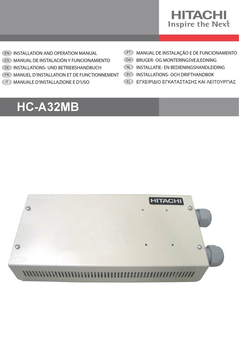
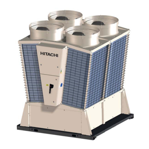
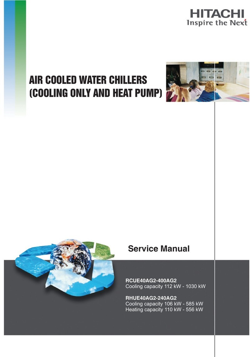
Hitachi SAMURAI Series User manual

RCME-(40-70)WH1
Service Manual
SAMURAI SERIES
WATER COOLED WATER CHILLERS
-MODULAR-R134a-SCREW TYPE-


General Index
SMGB0120 rev.0 - 11/2017
III
General Index
1. General information................................................................................................... 1
1.1 General notes..........................................................................................................................................2
1.2 Safety and applied symbols .................................................................................................................... 3
1.2.1 Norms and Regulations................................................................................................................................... 3
1.3 Product guide ..........................................................................................................................................4
1.3.1 Classication of water chiller models .............................................................................................................. 4
1.3.2 Product guide: Water chillers........................................................................................................................... 4
2. Control Functions ...................................................................................................... 5
2.1 Control functions on the module.............................................................................................................. 6
2.1.1 Water control ................................................................................................................................................... 9
2.1.2 Water temperature control............................................................................................................................. 10
2.1.3 Compressor Control ...................................................................................................................................... 13
2.1.4 Control for recovery from power interruption (Option)................................................................................... 15
2.1.5 Prevention of simultaneous startup ............................................................................................................... 16
2.1.6 Reverse prevention control ........................................................................................................................... 16
2.1.7 Control for prevention of wrong operation and wrong settings...................................................................... 17
2.1.8 Demand control ............................................................................................................................................. 17
2.1.9 Forced load up capacity control from external signal .................................................................................... 21
2.1.10 2-temperature setting function..................................................................................................................... 22
2.1.11 External thermo operation from external contact......................................................................................... 23
2.1.12 Water Temperature of the Control Target .................................................................................................... 25
2.1.13 Operation from DC24V contact input .......................................................................................................... 26
2.1.14 Thermo OFF function selection ................................................................................................................... 31
2.1.15 Selection of enabling/disabling of alarm release by means of remote stop ................................................ 32
2.1.16 Limitation setting for pump feedback waiting time....................................................................................... 33
2.1.17 Inlet water temperature thermo OFF function ............................................................................................. 34
2.2 Control of the cooling cycle ................................................................................................................... 36
2.2.1 Compressor Control ...................................................................................................................................... 36
2.2.2 Expansion Valve Control ............................................................................................................................... 37
2.2.3 Overcurrent protection control....................................................................................................................... 39
2.3 Control of Master/Slave group...............................................................................................................40
2.3.1 Summary of control of Master/Slave group ................................................................................................... 40
2.3.2 Setting method .............................................................................................................................................. 40
2.3.3 Operation method.......................................................................................................................................... 41
2.3.4 Other functions of the control of Master/Slave group .................................................................................... 43
2.3.5 Setting items.................................................................................................................................................. 44
2.3.6 Method for setting and conrmation of operation conditions through the LCD screen.................................. 46
2.4 Run operation........................................................................................................................................48

General Index
SMGB0120 rev.0 - 11/2017
IV
2.4.1 Setting of switches on the setting PCB ......................................................................................................... 48
2.4.2 Operation control of the module .................................................................................................................... 49
2.5 Time chart .............................................................................................................................................50
3. Servicing................................................................................................................... 51
3.1 LCD display for Service Menu............................................................................................................... 53
3.2 General notes........................................................................................................................................61
3.3 Cycle components.................................................................................................................................62
3.3.1 Compressor removal ..................................................................................................................................... 62
3.3.2 Overhaul work ............................................................................................................................................... 65
3.3.3 Recovering the refrigerant............................................................................................................................. 67
3.3.4 Replacement of the condenser ..................................................................................................................... 67
3.3.5 Replacement of the cooler ............................................................................................................................ 69
3.3.6 Replacement of expansion Valve .................................................................................................................. 70
3.3.7 Filter drier ...................................................................................................................................................... 71
3.3.8 Replacement of the check valve ................................................................................................................... 72
3.3.9 Replacement of the stop valve (with check joint) .......................................................................................... 73
3.3.10 Replacement of the high pressure switch (PSH)......................................................................................... 73
3.3.11 Replacement of the pressure sensor (Pd)................................................................................................... 73
3.3.12 Replacement of the pressure sensor (Ps)................................................................................................... 73
3.3.13 Replacement of the pressure sensor (PSW)............................................................................................... 74
3.3.14 Replacement of the pressure relief valve .................................................................................................... 74
3.3.15 Replacement of the sight glass ................................................................................................................... 74
3.3.16 Replacement of the stop valve (x3)............................................................................................................. 74
3.3.17 Repalacement of the thermistor (Suction, THMs) ....................................................................................... 75
3.3.18 Replacement of the thermistor (Discharge, THMd)..................................................................................... 75
3.3.19 Replacement of the crankcase heater (CH) ................................................................................................ 75
3.3.20 Replacement of the thermistor (Evaporation, THMe).................................................................................. 76
3.3.21 Replacement of the thermistor (Cooler water inlet, THMwi)........................................................................ 76
3.3.22 Thermistor (Cooler water outlet, THMwo2) ................................................................................................. 77
3.3.23 Thermistor (Cooler water outlet, THMwo) ................................................................................................... 77
3.3.24 Replacement of the solenoid valves (SVa, SVb, SVc) ................................................................................ 77
3.4 Electrical components ...........................................................................................................................78
3.4.1 The E-box...................................................................................................................................................... 78
3.4.2 Removal of the LCD screen .......................................................................................................................... 78
3.4.3 Replacement of lamps and push buttons ...................................................................................................... 79
3.4.4 Access to electrical components ................................................................................................................... 79
3.4.5 Removal of the PCB’s ................................................................................................................................... 81
3.4.6 Transformer (TF1) ......................................................................................................................................... 83
3.4.7 Transformers (TF2, TF3, TF4)....................................................................................................................... 83
3.4.8 Overcurrent relay (ORC) ............................................................................................................................... 83
3.4.9 Contactors (CMC, CMCD, CMCS) ................................................................................................................ 84

General Index
SMGB0120 rev.0 - 11/2017
V
3.4.10 Fuses (EF1, EF2, EF3. EFR, EFS, EFT) .................................................................................................... 84
3.4.11 Fuses (PFC) ................................................................................................................................................ 85
3.4.12 Relays ......................................................................................................................................................... 86
3.4.13 Main Switch ................................................................................................................................................. 87
4. Troubleshooting....................................................................................................... 89
4.1 Inspection of power source and connections ........................................................................................90
4.2 Inspection of PCB..................................................................................................................................91
4.3 Conrmation of operating value of protection devices and automatic operation devices ..................... 91
4.4 Protection control function..................................................................................................................... 92
4.5 Alarm indication.....................................................................................................................................93
4.6 Summary of fault diagnosis................................................................................................................... 94
4.7 Method for fault diagnosis ..................................................................................................................... 96
4.8 Troubleshooting by alarm code ............................................................................................................. 97
4.9 Analysis and countermeasure of abnormalities...................................................................................121
4.10 Thermistor characteristics ................................................................................................................... 127
4.10.1 Thermistor temperature characteristics (All temperature except discharge gas) ...................................... 127
4.10.2 Thermistor temperature characteristics for discharge gas temperature.................................................... 127
4.11 Pressure sensor characteristics .......................................................................................................... 128
4.11.1 High-pressure sensor ................................................................................................................................ 128
4.11.2 Low-pressure sensor ................................................................................................................................. 128
4.12 Procedures for trouble.........................................................................................................................128


1 General information
SMGB0120 rev.0 - 11/2017
1
1
1. General information
Index
1.1 General notes..........................................................................................................................................2
1.2 Safety and applied symbols .................................................................................................................... 3
1.2.1 Norms and Regulations................................................................................................................................... 3
1.3 Product guide ..........................................................................................................................................4
1.3.1 Classication of water chiller models .............................................................................................................. 4
1.3.2 Product guide: Water chillers........................................................................................................................... 4

1 General information
General notes
SMGB0120 rev.0 - 11/2017
2
1.1 General notes
© Copyright 2017 Johnson Controls-Hitachi Air Conditioning Spain, S.A.U. – All rights reserved.
No part of this publication may be reproduced, copied, led or transmitted in any shape or form without the permission of
Johnson Controls-Hitachi Air Conditioning Spain, S.A.U..
Within the policy of continuous improvement of its products, Johnson Controls-Hitachi Air Conditioning Spain, S.A.U.
reserves the right to make changes at any time without prior notication and without being compelled to introducing them
into products subsequently sold. This document may therefore have been subject to amendments during the life of the
product.
HITACHI makes every effort to offer correct, up-to-date documentation. Despite this, printing errors cannot be controlled
by HITACHI and are not its responsibility.
As a result, some of the images or data used to illustrate this document may not refer to specic models. No claims will
be accepted based on the data, illustrations and descriptions included in this document.
No type of modication must be made to the equipment without prior, written authorisation from the manufacturer.
HITACHI pursues a policy of continuing improvement in design and performance of products. The right is therefore
reserved to vary specications without notice.
HITACHI cannot anticipate every possible circumstance that might involve a potential hazard.
No part of this document may be reproduced without written permission.
If you have any questions, contact your service contractor of HITACHI.
Check and make sure that the explanations of each part of this document correspond to your model.
Refer to the models codication to conrm the main characteristics of your system.
Signal words (DANGER, CAUTION and NOTE) are used to identify levels of hazard seriousness. Denitions for
identifying hazard levels are provided below with their respective signal words.
It is assumed that this unit will be operated and serviced by English speaking people. If this is not the case, the customer
should add safety, caution and operating signs in the native language of the personal.
This water chiller has been designed for the working range described in the corresponding chapter.

1 General information
Safety and applied symbols
SMGB0120 rev.0 - 11/2017
3
1
1.2 Safety and applied symbols
During normal system design work or unit installation, greater attention must be paid in certain situations requiring
particular care in order to avoid damage to the unit, the installation or the building or property.
Situations that jeopardise the safety of those in the surrounding area or that put the unit itself at risk will be clearly
indicated in this manual.
To indicate these situations, a series of special symbols will be used to clearly identify these situations.
Pay close attention to these symbols and to the messages following them, as your safety and that of others depends on
it.
!DANGER
• Thetextfollowingthissymbolcontainsinformationandinstructionsrelatingdirectlytoyoursafetyandphysicalwellbeing.
• Nottakingtheseinstructionsintoaccountcouldleadtoserious,veryseriousorevenfatalinjuriestoyouandothersinthe
proximityoftheunit.
• Hazardsorunsafepracticeswhichcouldresultseverepersonalinjuryordeath.
In the texts following the danger symbol you can also nd information on safe procedures during unit installation.
!CAUTION
• Thetextfollowingthissymbolcontainsinformationandinstructionsrelatingdirectlytoyoursafetyandphysicalwellbeing.
• Nottakingtheseinstructionsintoaccountcouldleadtominorinjuriestoyouandothersintheproximitiesoftheunit.
• Nottakingtheseinstructionsintoaccountcouldleadtounitdamage.
In the texts following the caution symbol you can also nd information on safe procedures during unit installation.
?NOTE
• Thetextfollowingthissymbolcontainsinformationorinstructionsthatmaybeofuseorthatrequireamorethoroughexplanation.
• Instructionsregardinginspectionstobemadeonunitpartsorsystemsmayalsobeincluded.
1.2.1 Norms and Regulations
Appropriaterefrigerant
The refrigerant used in each unit is identied on the specication label and manuals of the unit. HITACHI shall not be
held liable for any failure, trouble, malfunction or accident caused by units illegally charged with refrigerants other than
the specied one.
Consequencesofchargingnon-speciedrefrigerant
It may cause mechanical failure, malfunction and other accidents. It may cause operational failure of protection and
safety devices of air conditioners. It may also cause lubrication failure of the sliding part of the compressor due to
deterioration of refrigerant oil.
In particular, hydrocarbon refrigerants (such as propane, R441A, R443A, GF-08, etc.) are not allowed, since these are
combustible and may cause major accidents such as re and explosion in case of improper handling.
Once a non-specied refrigerant has been charged, no further servicing (including draining of refrigerant) shall be
performed, even in case of malfunction. Improper handling of refrigerant may be a cause of re and explosion, and
servicing in such cases may be considered an illegal act.
End clients and costumers shall be informed that servicing is not approved, and the installer who charged the non
specied refrigerant shall be asked to x the unit.
HITACHI will accept no responsibility for units that have been charged with non-specied refrigerant once.

1 General information
Product guide
SMGB0120 rev.0 - 11/2017
4
1.3 Product guide
1.3.1 Classication of water chiller models
Basic modules
Unit type (Modular water chiller): RCM
E = Made in Europe
Position-separating hyphen (xed)
Capacity (HP): 40, 50, 60, 70
W = Water cooled
H = R134a refrigerant
Serie
RCM E – XX W H1
1.3.2 Product guide: Water chillers
Basic modules
3N~ 400V 50Hz
Unit Code
RCME-40WH1 8E040341
RCME-50WH1 8E050341
RCME-60WH1 8E060341
RCME-70WH1 8E070341

2 Control Functions
SMGB0120 rev.0 - 11/2017
5
2
Index
2.1 Control functions on the module..............................................................................................................6
2.1.1 Water control ................................................................................................................................................... 9
2.1.2 Water temperature control............................................................................................................................. 10
2.1.3 Compressor Control ...................................................................................................................................... 13
2.1.4 Control for recovery from power interruption (Option)................................................................................... 15
2.1.5 Prevention of simultaneous startup ............................................................................................................... 16
2.1.6 Reverse prevention control ........................................................................................................................... 16
2.1.7 Control for prevention of wrong operation and wrong settings...................................................................... 17
2.1.8 Demand control ............................................................................................................................................. 17
2.1.9 Forced load up capacity control from external signal .................................................................................... 21
2.1.10 2-temperature setting function..................................................................................................................... 22
2.1.11 External thermo operation from external contact......................................................................................... 23
2.1.12 Water Temperature of the Control Target .................................................................................................... 25
2.1.13 Operation from DC24V contact input .......................................................................................................... 26
2.1.14 Thermo OFF function selection ................................................................................................................... 31
2.1.15 Selection of enabling/disabling of alarm release by means of remote stop ................................................ 32
2.1.16 Limitation setting for pump feedback waiting time....................................................................................... 33
2.1.17 Inlet water temperature thermo OFF function ............................................................................................. 34
2.2 Control of the cooling cycle ................................................................................................................... 36
2.2.1 Compressor Control ...................................................................................................................................... 36
2.2.2 Expansion Valve Control ............................................................................................................................... 37
2.2.3 Overcurrent protection control....................................................................................................................... 39
2.3 Control of Master/Slave group...............................................................................................................40
2.3.1 Summary of control of Master/Slave group ................................................................................................... 40
2.3.2 Setting method .............................................................................................................................................. 40
2.3.3 Operation method.......................................................................................................................................... 41
2.3.4 Other functions of the control of Master/Slave group .................................................................................... 43
2.3.5 Setting items.................................................................................................................................................. 44
2.3.6 Method for setting and conrmation of operation conditions through the LCD screen.................................. 46
2.4 Run operation........................................................................................................................................48
2.4.1 Setting of switches on the setting PCB ......................................................................................................... 48
2.4.2 Operation control of the module .................................................................................................................... 49
2.5 Time chart .............................................................................................................................................50
2. Control Functions

2 Control Functions
Control functions on the module
SMGB0120 rev.0 - 11/2017
6
2.1 Control functions on the module
List of the main control functions
Item Description
Automatic water
temperature control
1 Slide valve control
The outlet water temperature of the chiller unit is detected with a thermistor, and the stroke of slide valve is
controlled continuously by time-sharing.
Setting Temperature Neutral Zone
Load down area
(Hold)
Load up area
Example of cooling operation: Outlet Water Temperature
Capacity control range: 100~25%, Stop.
2 Thermo ON-OFF control
When operation load becomes light, outlet water temperature falls below the "Stop temperature range" against
the lower limit temperature in neutral zone (in the case of cooling operation; increase in the case of heating
operation). By doing so, the compressor stops (Thermo OFF).
The settings of stop temperature range can be changed locally between 0.5 and 2.0ºC (in 0.5ºC steps).
Example of cooling operation:
Lower limit in
neutral zone
Stop temperature range
Outlet water temperature
Thermo OFF
Also, in case that water temperature increases above "Recovery temperature range" against inlet temperature
when Thermo ON is set (in the case of cooling operation; decrease in the case of heating operation), the
compressor starts (Themo ON). (However, there is a time guard with a minimum of 3 minutes )
It is possible to change the settings of recovery temperature range, but take into account that the water volume
necessary to maintain the frequency of compressor run/stop will be different.
Compressor Control
Once that "Compressor delay time" has passed after pump startup, compressor starts up with
Υ
-Δ control,
performs startup unload control during 60 seconds, and then shifts to capacity control.
The settings of Compressor delay time can be changed in the range between 30 seconds and 10 minutes (in
30 second steps).
Set a delay time adjusted to the characteristics of the installation, to prevent compressor startup until a
sufcient ow of cold water can be ensured after pump startup. Default: 30 seconds.
Recovery from
momentary power
failure
Compressor is temporarily stopped when a momentary power failure (drop of more than 20% of power source
voltage detected for a period between 13 milliseconds and 2 seconds) occurs, and it is automatically restarted
after time guard time has passed. Also, momentary power failure detection signal is output during 10 seconds
upon detection of momentary power failure.
Automatic recovery
from power
interruption
(Option)
It is possible to restart automatically after recovery from a power interruption (or power source OFF) exceeding
2 seconds.
?NOTE
• Itreturnstothestate immediately before theoccurrenceofpower interruption. In case thattheunitwas
stoppedbeforepowerinterruption,itremainsstopped.
• Sincethisfunctionisoptional,itisnecessarytomakethesettingsfortheenablingofthisfunctionatthetime
oflocalinstallation.
• SincethereisthepossibilitythatoperationstartsabruptlyuponpowerON,giventhecircumstancesatthe
timeofpowerOFF,becarefulenoughwhenenablingthisfunction.
Reverse prevention The status of the three phases of power input is monitored, to prevent operation in reverse and open phase.

2 Control Functions
Control functions on the module
SMGB0120 rev.0 - 11/2017
7
2
Item Description
Incorrect operation
prevention
It is not possible to switch between remote and main unit control, and between cooling and heating, during
operation of the chiller unit. An alarm is output with respect to such incorrect operation, and to wrong DIP switch
settings. Also, an alarm is output to prevent danger, in case that an operation order is input from a remote when
settings are for main unit control.
Demand control
Compressor operation can be limited by external signal input.
Forced thermo OFF: Compressor is stopped forcedly during external signal input.
Current limit function: Operation capacity is limited to make the running current lower than the setting value of
current limit control, during external signal input. Limit value can be changed by local settings.
Forced load-up: Load-up output is conducted forcedly during external signal input.
Capacity hold: Capacity control is ignored forcedly during external signal input.
2 temperature
setting
Cooling operation and heating operation have 2 setting temperatures each, and it is possible to select which
setting temperature is valid by external signal input. In case of operating with a different extraction temperature,
such as heat storage or air conditioning, it is not necessary to change the setting temperature of the main
chiller unit.
Forced load up from
external contact
Forced load up is conducted during outdoor order (non-voltage a contact) input.
It is possible to select whether "the pump shall stop" or "the pump can be kept working" in the event of a thermo
OFF, when thermo OFF judgement at the main unit is enabled.
(This function cannot be used when the function to control the number of units is used )
Information about
overhaul period
Compressor operation time for preventive maintenance is monitored, and when it reaches the overhaul period,
the "Overhaul mark" is shown on the LCD screen.
Disabling of remote
stop alarm clear
(Option)
It is possible to disable the release of alarms by remote stop order input.
?NOTE
• Normally,alarmscanbereleasedbystopcontrolfromeitherremoteorthemainunit.
• Sincethisfunctionisoptional,itisnecessarytomakethesettingsfortheenablingofthisfunctionatthetime
oflocalinstallation.
Limit of waiting time
for pump feedback
(Option)
It is possible to determine pump interlock abnormality and output an alarm in case that no pump feedback
signal is input after a certain amount of time has passed upon startup of the chiller unit.
This time can be changed by local settings, between 1 and 30 minutes (in 1 minute steps).
?NOTE
Thedefaultfeedbackwaitingtimeis"unlimited".
Thermo OFF
judgement delay
(Option)
It is possible to delay the judgement time of thermo OFF to avoid immediate thermo OFF when water
temperature reached thermo OFF judgement value due to uctuations in the amount of cold water ow, caused
by momentary variations in load or the activation of valves, etc.
?NOTE
• Sincethisfunctionisoptional,itisnecessarytomakethesettingsfortheenablingofthisfunctionatthetime
oflocalinstallation.
• ThermoOFFisproducedwhenreachingoperationlimittemperature,evenifbeinginjudgementtime.
Thermo OFF
judgement due to
inlet temperature
It is possible to determine thermo OFF from the inlet water temperature (return temperature from load) of the
chiller unit. It is possible to change the settings of thermo OFF temperature.
?NOTE
Sincethisfunctionisoptional,itisnecessarytomakethesettingsfortheenablingofthisfunctionatthetimeof
localinstallation.
Preservation of
alarm data
When an alarm occurs, the contents of the alarm, as well as the date and time of occurrence are recorded.
The most recent 10 cases are stored, and then they are deleted from the oldest. Also, for the most recent 3
cases, the data of each sensor (right before occurrence, 10 seconds before and 20 seconds before) as well as
data regarding each setting and operation conditions are stored, and it is possible to check them later on. This
supports the early identication of the causes of alarm occurrence.

2 Control Functions
Control functions on the module
SMGB0120 rev.0 - 11/2017
8
Item Description
Water Temp Set Setting is possible in 0.5ºC units.
Display
Main unit side
LCD device: Displays the status of the chiller unit (Run, stop, contents of alarm, operating pressure and
temperature, etc.)
7-Segment (for backup of the LCD): Displays the status of the unit and content of alarms with individual codes
Pilot lamps: Lit on for power source: white, run: red, alarm: orange
Remote display
Outputs operation of the chiller unit, cool/heat mode, pump operation, alarm, warning and defrosting
Control of Master/
Slave group
(Module Control)
(Option)
When installing multiple units, operation as one entire heat system is possible by connecting each chiller unit
through H-LINK.
It is possible to connect a maximum of 8 units to one group.
?NOTE
• Sincethisfunctionisoptional,itisnecessarytomakethesettingsfortheenablingofthisfunctionatthetime
oflocalinstallation.
• Anexclusivecontrollerisnotrequired,butoptionalpartsmaybecomenecessarydependingonthestructure
ofthelocalsystem.

2 Control Functions
Control functions on the module
SMGB0120 rev.0 - 11/2017
9
2
2.1.1 Water control
Outlet water temperature of Chiller Unit is detected by Thermistor, and based on this value, compressor ON/OFF and the
most suitable capacity is determined. Following shown the continuous capacity control and change of water temperature.
9ºC
8ºC
7ºC
6ºC
5ºC
(0.5~5.0ºC)
(0.5~2.0ºC)
(1.0~3.0ºC)
T4
Δ
Tsc:7ºC
T1: 1ºC
T2: 2ºC
T3: 2ºC
T4: 1ºC
Δ
Δ
Δ
Δ
Tsc (setting t.)
T1Δ
T2Δ
T3Δ
Tsc+ T2/3+ T4ΔΔ
Tsc+ T2/3Δ
Tsc- T2/3Δ
Tsc- T2/3- T1ΔΔ
T3Δ
T4Δ
T1Δ
(1.0~4.0ºC)
T2Δ
Outlet
temperature Inlet
temperature
Stop
(Thermo off)
Start
(re-start)
Memorizes the inlet temperature
at Thermo-OFF and re-start at
∆T2
Load up I zone
Load up II zone
Load Down zone
Thermo-off zone
Load up I
status
Load up II
status
Neutral status Load-down status Stop
status
Load up II
status
Neutral
status
Neutral status
Neutral zone
Starting setting
(example)
Method of outlet temperature detection
1 Load-up I control at over 9°C (The capacity is changed a lot in order to approximate the target temp. quickly)
2 Load-up II control at 8~9°C (The capacity is changed moderately)
3 In neutral zone (6~8°C), load is balanced and performance is not changed.
4 Under neutral zone (below 6°C) load-down control is performed and performance is decreased.
5 Stop temp: Compressor is stopped at 5°C. The inlet temp of that time is saved.
6 When inlet temp becomes 2°C higher than that of at stop, re-start signal is output and unit is re-started after at least 3
min guard.

2 Control Functions
Control functions on the module
SMGB0120 rev.0 - 11/2017
10
2.1.2 Water temperature control
1 Automatic temperature adjustment
Compressor run/stop and capacity control are performed by detecting water temperature of the chiller unit with
thermistors.
Item
Model
Water Temp Set ON/OFF Temperature Difference Stop Temperature Range
Available range
(ºC) Step (ºC) Setting range
(ºC) Step (ºC)
Water-cooled
cooling only 4~30 0.5 0~4
Default: 2 10.5~2.0
Default: 1.0
0.5
?NOTE
• ReturntemperaturerangeindicatestheamountofchangeininletwatertemperatureofthechillerunittodeterminethermoONafter
thermoOFF.(Inthecaseofcooling:amountoftemperatureincrease;inthecaseofheating:amountoftemperaturedecrease)
• Itispossibletochangesettingslocallydependingonusagepurpose,butsincethenecessaryvolumeofwaterwillchange,changethe
settingsonlyuponconrmationoftheamountoftheretainedvolumeofwaterintheentirelocalsystem.
Output Cycle Load up I
Output time
Load up II
Output time
Load down
Output time
Setting range
(Seconds)
10~120
(Default: 30)
10~120
(Default: 10)
2~120
(Default: 2)
2~120
(Default: 2)
Step
(Seconds) 10 1 1 1
Neutral Zone Range Load up II range
Setting range (ºC) 1~5 (Default: 2) 1~3 (Default: 1)
Step (ºC) 1 1
?NOTE
• ReturntemperaturerangeindicatestheamountofchangeininletwatertemperatureofthechillerunittodeterminethermoONafter
thermoOFF.(Inthecaseofcooling:amountoftemperatureincrease;inthecaseofheating:amountoftemperaturedecrease).
• Itispossibletochangesettingslocallydependingonusagepurpose,butsincethenecessaryvolumeofwaterwillchange,changethe
settingsonlyuponconrmationoftheamountoftheretainedvolumeofwaterintheentirelocalsystem.

2 Control Functions
Control functions on the module
SMGB0120 rev.0 - 11/2017
11
2
2 Method to change settings
a. Water temperature settings
Select the setting value
with up and down keys
Register with [ENT] key
Cancel with [CAN] key
INPUT
COOL COOL/HEAT
The part with the setting temperature
currently enabled is illuminated
INPUT
?NOTE
• [Set1]:Thisisthesettingvalueofthemasterchillerunit,andwatertemperaturecontrolisnormallyperformedagainstthissetting
value.
• [Set2]:Thisisthesettingvaluewhen2temperaturesettingfunctionisenabled.
• [Ext]:Thesettingvaluefromanexternalsourceisdisplayed,suchaswhen(aslaveunit)followingthesettingofthemasterunits,or
whenconnectingtoagroupcontroller.

2 Control Functions
Control functions on the module
SMGB0120 rev.0 - 11/2017
12
b. Setting of other water temperature control settings
Display the input window with [INPUT] key
Input the setting value with up and down
keys
Register the input value and close the
window by pressing the [ENT] key. Also,
by pressing the [CAN] key the input
value is not registered, and the window is
closed.
Continuous control type
Other manuals for SAMURAI Series
3
This manual suits for next models
9
Table of contents
Other Hitachi Chiller manuals
Popular Chiller manuals by other brands

McQuay
McQuay PFS-150B installation manual

Acson international
Acson international A5ACV 30 CR manual

AIREDALE
AIREDALE ULTIMA URAC75D Technical manual

Traulsen
Traulsen KROGER RBC50 Specifications

Haier
Haier CA0100MANB Installation, operation and technical manual

SMC Networks
SMC Networks HRS-R Series Operation manual

Polar Refrigeration
Polar Refrigeration CB929 instruction manual

Daikin
Daikin EWWP014KBW1N Operation manual

TecoPonic
TecoPonic HYDROPONIC HY 500 manual

AIREDALE
AIREDALE TurboChill TCC1 Series installation manual

Sinclair
Sinclair SCV-750EB Service manual

Sterlco
Sterlco Sterlco Series R RTAA-110 Installation and maintenance manual