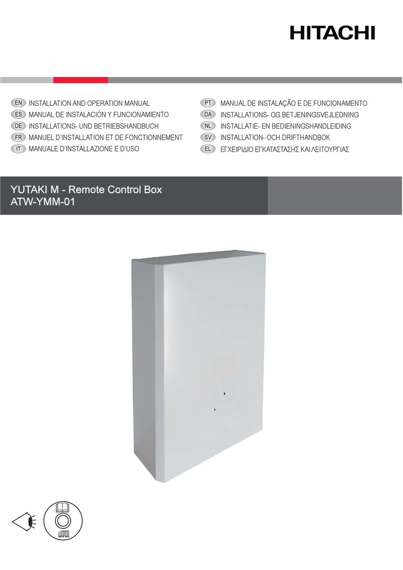
Hitachi PSC-A32MN User manual

CENTRAL STATION
PSC-A32MN
INSTRUCTION MANUAL

1 SAFETY SUMMARY
This product has been designed for air conditioning systems.
!DANGER
• DO NOT pour water into the central station (hereafter called
“controller”). This product is equipped with electrical parts. If
waterispoured,itwillcauseaseriouselectricalshock.
• Prior to the installation work, ensure that foundation is at,
levelandsufcientlystrongandthenxtheunitsecurely.Ifthe
foundationisnotstrongenough,itmayleadtoinjuriescausedby
fallingoftheproduct,electricalshockorre.
• DO NOT install the unit in a place where generation, ow,
accumulationorleakageofammablegasisdetected.
• DONOTperforminstallationworkandelectricalwiringconnection
by yourself. Contact your distributor or dealer of HITACHI and
askthemforinstallationworkandelectricalwiringbyatrained
serviceperson.
• PerformelectricalworkaccordingtotheInstallationManualand
allrelevantregulationandstandards.Iftheinstructionsarenot
followed,electricalshockandremayoccurduetoinsufcient
capacityandinadequateperformance.
• Usethespeciedcablesforconnectionbetweenindoorunitand
central station. Selecting incorrect cables may lead to re or
electricalshock.
• Turn OFF the main power supply entirely before opening or
closing the service cover of the indoor unit, since the power
terminalorthepowerswitchpartmayotherwisebestillpowered
on and cause an electrical shock. Turn OFF the main power
supplyalsowhenperformingwiringworks.
• When performing local wiring work, check whether the local
wiringhasbeengnawedbyanimalslikemiceorsmallrodents.
Gnawedwiringcouldcauseare.
!CAUTION
• DONOTinstalltheindoorunit,outdoorunit,centralstationandcable
inthefollowingplaces;
-Whereoilvapouroroilisdispersed(Itmaycauseare,
deformation,corrosionorfailure.)
-Inthevicinityofhotsprings(inasulphuricenvironment)
-Inthevicinityofthesea(inasaltyenvironment,whichmaycause
corrosion.)
-Inanacidoralkalineenvironment
-Atthereachofchildren
-Underdirectblowofdischargeairfromtheunit
-Inplaceswithhumidatmosphere
-Inplaceswheretheunitmaygetwet
-Inpoorlyventilatedplaces
• DONOTinstalltheindoorunit,outdoorunit,centralstationandcable
within approximately 3 metres from strong electromagnetic wave
radiatorssuchasaradio.
• In case that the central station is installed in a place where
electromagneticwaveradiationisgenerated,shieldthecentralstation
andcablesbycoveringtheunitwithasteelboxandrunningthecable
throughametalconduittube.
!CAUTION
• This appliance must be used only by adult and capable people,
havingreceivedthetechnicalinformationorinstructionstohandlethis
applianceproperlyandsafely.
• Childrenshouldbesupervisedtoensurethattheydonotplaywiththe
appliance.
2 COMPONENTS LIST
When unpacking Central Station PSC-A32MN, check that it has not suffered damage during transport.
Check to ensure that the following parts are packed with the central station.
Name Quantity Comments
Central station PSC-A32MN 1For controlling system operation
M4x16L screws 4 For xing the central station.
Touch pen 2 For activating/deactivating the touch options on the screen.
Touch pen holder 1 For holding the touch pen on the central station.
USB stick memory 1 With the detailed Installation and operation manual
Instruction manual 1Basic instructions for the installation of the device.
Connector Cord 3 For using external input/output functions (CN1~3).
Closed End Connector 9 For closing the wire end of the connection cord.
Nylon Band 3 For xing the cables.
Safety summary
PMML0364B rev.0 - 05/2015
1

3 INSTALLATION
Check installation instructions inside the USB Pen Drive Memory.
3.1 SELECTION OF INSTALLATION PLACE
Select a suitable place for handling and determine the installation
place of the central station with the customer’s acceptance.
Do not install the central station in places which are at the reach
of children or where the air from the air conditioner is directly
discharged.
Prior to the installation work, ensure that the foundation is at,
level and sufciently strong, and then x the unit securely. If the
foundation is not strong enough, it may lead to injuries caused by
falling of the product, electrical shock or re.
Before installing the controller, prepare the following items.
Parts Specication
Switch Box JIS switch box for 2 switches (with cover)
(JIS C 8340)
Power Supply Cable Cable specication: 1.25 to 2 mm2
Recommended cable: 600V CV, CCV, CEV
H-LINK Cable
(For control)
Cable SPEC: 0.75 to 1.25 mm2
Recommended cable: JKEPV-S, JKEV-S,
CVV-S, CVV, 600V VCT
* The recommended cables are the model name of Hitachi Cable, Ltd.
3.2 INSTALLATION SPACE
Keep the installation space for the central station as shown below.
( U n i t : m m )
22 52.7
70
50
120
30
140 30
30
When installing two or more central stations
side by side, keep the following separation
between each of them.
* Vertical space: 50mm
* Horizontal space: 30mm
Do not place anything in the shaded area “ ”.
3.3 INSTALLATION PROCEDURE
1 Install the switch box into the wall. (Field supplied JIS switch
box for 2 switches (with cover) (JIS C 8340))
2 Open the unit case, in case that it is closed. (It is shipped
opened from the factory). Follow the procedure below to open
the case.
a. Remove the front side of the case by inserting and
rotating a tool like the tip of a slotted screwdriver in the
notches (2 notches on the lower side).
b. To open the case, pull up the front side from the bottom
and unhook the tabs at the upper and lateral sides. Do
not apply an excessive force when opening the front and
rear sides of the case, as they are joined with connection
bands.
Front case
Rear case
Catch
for xing
Connection band
Front case
Approx. 6 mm
Slotted screw driver
View from lower side
Installation
PMML0364B rev.0 - 05/2015
2

3 Connect the wiring to the terminal board of the central station.
Terminal Board Use Connection procedure
H-LINK (Non-pole)
Terminals for external input/output
FG
AC100 to 240V
TB1 For power supply M3 screw-on terminal
Round terminal connection
Tightening torque 0.5N·m
TB2 For H-LINK transmission
CN1 ~ 3 For external input/output
3-pin connector
Insert connector cords (accessory)
until hearing a click.
4 Fix the switch box (eld-supplied JIS switch box for 2 switches (with cover) (JIS C 8340)) using the accessory xing screw
(M4 × 16 mm).
M4 screws
(Q’ty: 4)
Switch box (Field-supplied)
(JIS C8340 2 switches (with cover))
4 GENERAL DATA
Model PSC-A32MN
Outer Dimension
<W x H x D + (Built-in Part)> 140 × 120 × 22 + 52.7 (mm)
Net Weight 0.5 kg (approx.)
Installation Location Indoor
Installation Method Wall built-in with
JIS switch box for 2 switches (with cover) (JIS C 8340)
Connected Indoor Units (Quantity) 160 (Max.)
Clock Accuracy ± 70 seconds/month (at normal temperature)
Ambient Temperature 5 ~ 35°C
Ambient Humidity 35 ~ 90% (No dew condensation)
Display 5.0” TFT colour liquid crystal display
Rated Power Supply 1~, 100~240V, 50/60Hz
Electrical Power Consumption 20W (Max.)
General data
PMML0364B rev.0 - 05/2015
3

Printed in Spain
00000
Other manuals for PSC-A32MN
3
Table of contents
Other Hitachi Control System manuals
Popular Control System manuals by other brands

Galaxy Control Systems
Galaxy Control Systems BIOSCRYPT L-1 Configuration & operation guide

FAAC
FAAC B614 manual

Onstep
Onstep EQ5 GoTo Build instructions

SkyAzúl
SkyAzúl Krupp EKS 83 Service manual

LOGICDATA
LOGICDATA LogicS Mounting instructions

UTAH SCIENTIFIC
UTAH SCIENTIFIC SC-4 Set up and operation guide