Hitachi CC41R1 User manual

i
MN1-6264 Rev.2
Notes for operators and responsible maintenance personnel
★
Please read through this Instruction Manual as well as the separate Instruction
Manual “Safety (MN1-5990)” and “Cleaning, Disinfection and Sterilization
(MN1-6161)“ carefully prior to use.
★
Keep this Instruction Manual together with the ultrasound diagnostic instru-
ment for any future reference.
© Hitachi, Ltd. 2016, 2017. All rights reserved.
CC41R1 Probe
Instruction Manual
Specication
MN1-6264 Rev.2

ii
MN1-6264 Rev.2

iii
MN1-6264 Rev.2
Introduction
This is the instruction manual for CC41R1 probe. The probe is available by connecting to Hitachi's ultrasound
diagnostic instrument and can be used as a transrectal probe for observation of prostate and surrounding organs or
used as a vaginal probe for observation of uterus and surrounding organs. It can also be used for ultrasound-guided
puncture under the condition that the optional puncture adapter is attached to it.
Prior to use, read this manual as well as the separate instruction manual “Safety” in which information for safe use is
provided.
The probe bears the CE mark but the mark is valid only when the probe is connected to the ultrasound diagnostic
instrument bearing the CE mark.
Symbols used in this document
Safety information is classied into Danger, Warning, Caution, and Note according to the level of hazard. Those terms
are used in safety information provided to prevent hazards and injuries to the operator or patient.
Danger
Indicates an imminently hazardous situation which, if not avoided, will result in death or serious injury to the
operator or patient.
Warning
Indicates a potentially hazardous situation which, if not avoided, could result in death or serious injury to the
operator or patient.
Caution
Indicates a potentially hazardous situation which, if not avoided, may result in minor or moderate injury to
the operator or patient, or property damage only.
Note
Indicates a strong request concerning an item that must be observed in order to prevent damage or
deterioration of the equipment and also to ensure that it is used efciently.
The type of safety information is indicated by the symbols below.
This symbol means that attention is required.
This symbol means that the described action is prohibited.
This symbol means that the described action is mandatory.

iv
MN1-6264 Rev.2
CONTENTS
1. General Information...................................................................................................................................1
1-1. Intended use...................................................................................................................................................................1
1-2. Classication of ME equipment....................................................................................................................................1
1-3. Standard components ....................................................................................................................................................1
1-4. Options ..........................................................................................................................................................................2
2. Specications and Parts name....................................................................................................................3
2-1. Specications.................................................................................................................................................................3
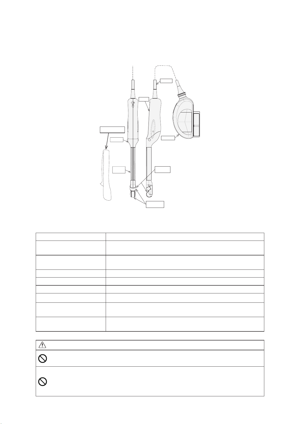
2-2. Name of each parts........................................................................................................................................................4
3. Preparations before use .............................................................................................................................5
3-1. Visual check ..................................................................................................................................................................5
3-2. Conrmation of cleaning, disinfection, and sterilization.............................................................................................5
3-3. Operation check.............................................................................................................................................................5
3-4. Visual check for the sterile puncture adapter (EZU-PA5V) ........................................................................................6
4. Operation....................................................................................................................................................7
4-1. Operation.......................................................................................................................................................................7
4-2. Relationship between the image and the orientation mark ..........................................................................................7
4-3. How to mount/remove the probe cover.........................................................................................................................8
4-3-1. How to mount the probe cover........................................................................................................................8
4-3-2. How to remove the probe cover......................................................................................................................9
4-4. How to attach the sterile puncture adapter...................................................................................................................9
4-5. Display of Puncture Guideline ................................................................................................................................... 11
4-6. How to attach/release the magnetic position sensor and the magnetic position sensor attachment..........................13
4-6-1. How to attach the magnetic position sensor and the magnetic position sensor attachment .......................13
4-6-2. How to release the magnetic position sensor and the magnetic position sensor attachment......................14
This instruction manual contains 4 pages of front matter and 16 pages of the main content.

-1-
MN1-6264 Rev.2
1. General Information
General information for the probe is provided below.
1-1. Intended use
This probe is intended to be used by a doctor or other qualied operator for ultrasonic observations of the prostate,
uterus, and surrounding organs. It can also be used for ultrasound-guided puncture.
Please refer to the ultrasound diagnostic instrument instruction manual used with this probe for the probe intended use
information.
Regarding with the connectable instrument, please refer to section 2-1. Specications of this manual.
Warning
Do not use this equipment for other than its intended use.
Otherwise it could cause burns or other injuries to the operator or the patient.
1-2. Classication of ME equipment
This probe is classied as follows according to IEC60601-1.
Please refer to the section 2-1 for the applied part, the part treated as the applied part, and the range of IPX7.
• Classication based on the degree of protection against electric shock ........ Type BF applied part
• Classication for protection against ingress of liquids .................................. IPX7 (Watertight equipment)
• Operation mode............................................................................................... Continuous operation
• Method of sterilization.................................................................................... Refer to the separate instruction manual
“Cleaning, Disinfection and Sterilization”
1-3. Standard components
The standard components of CC41R1probe are as follows.
CC41R1 Probe ······················································· 1 pc
Storage case ··························································· 1 set
Instruction Manual
• Specication (MN1-6264) ······································· 1 copy
• Safety (MN1-5990) ··············································· 1 copy
• Cleaning, Disinfection and Sterilization (MN1-6161) ······ 1 copy

-2-
MN1-6264 Rev.2
1-4. Options
The following options are available for CC41R1 probe.
• Puncture
Please use one of the options listed in Table 1 for performing a puncture. Please refer to the section 4-4 for how to
attach the sterile puncture adapter.
Table 1 Options for puncture
Product Name Product No. Remark
Sterile Puncture Adapter EZU-PA5V Applicable needle size: 16-19G
Packaging: 24pcs/box
• Probe cover
Please use the option listed in Table 2 for probe cover. Please refer to the section 4-3 for how to mount/remove the
probe cover.
Table 2 Option for probe cover
Product Name Product No.
Rubber Boot RB-945BP-NS
• Real Time Virtual Sonography (RVS)
Please use the option listed in Table 3 for performing RVS. Please refer to the section 4-6.
Table 3 Option for RVS
Product Name Product No.
Magnetic Sensor Attachment RV-015
• Reprocessing by liquid detergent, disinfectant or sterilant
Whole the probe is able to immerge into the liquids by putting the connector of the ultrasound probe to the
waterproof case WP-001 as below table 4.
Precautions about the waterproof case, please refer to the instruction manual.
Table 4 Accessory for reprocessing by liquid detergent, disinfectant or sterilant
Product Name Product No.
Waterproof case WP-001

-3-
MN1-6264 Rev.2
2. Specications and Parts name
The specications and the name of each part are provided below.
2-1. Specications
Application: Urological applications, Obstetric and gynecological areas
Type of patient contact: Transrectum, Transvaginal
Connectable instruments: ARIETTA 70, ARIETTA 60, ALOKA ARIETTA 850
NOTE:
At the time of publication of this manual, the connectable diagnostic ultrasound
instrument or instrument software version available with this probe is different for each
country, please refer to the instrument instruction manual or contact your local Hitachi
representative.
Field of view: 180° (Sagittal plane), 180° (Axial plane)
Frequency: 6.5 MHz (Sagittal plane), 6.5 MHz (Axial plane)
Cable length: 2.5 m
Service life: 3 years
Applied part: See Figure 1
Part treated as Applied part: See Figure 1
IPX7 range: See Figure 1 (In case that not putting the waterproof case to the ultrasound probe
connector)
In case that putting the waterproof case to the ultrasound probe connector, whole the
probe from the tip of the ultrasound probe to the connector with Waterproof Case WP-
001 is IPX7. range
Measurement accuracy: Refer to the instruction manual of the ultrasound diagnostic instrument
External dimensions: See Figure 1
Remark: The tolerance for the dimensions is ±10%.
Figure 1 External View
Cable length
IPX7 range
Applied part, Part
treated as applied part
Unit: mm

-4-
MN1-6264 Rev.2
2-2. Name of each parts
The name of each part is shown in Figure 2 and the explanation for each part is listed in Table 5.
Probe cover
Figure 2 Name of each parts
Table 5 Name of each part and its explanation
Name Explanation
Ultrasonic radiation part Ultrasound is radiated from this part. The electronic convex transducer is
integrated underneath this part.
Orientation mark side The side of the orientation mark corresponds to the side of the orientation
mark on the image. See 4-2.
Probe tip The probe tip is the part includes both the insertion portion and the handle.
Handle This part is held during operation.
Insertion portion This part is inserted into the patient.
Cable Cable transfers electric input/output signals.
Connector The connector is the part which is connected to the ultrasound diagnostic
instrument.
Probe cover This covers the insertion portion for preventing infection. Follow the
instructions in section 4-3.
Caution
Do not pull, bend, twist, or apply excessive force to the cable.
The probe may malfunction due to cable disconnection.
Do not subject the ultrasonic radiation part to hard impact.
The impact may cause damage to the transducer, and that results in noise or no echo in the image.
In most cases, the ultrasonic radiation part itself is not damaged because the part is made of elastic
material.

-5-
MN1-6264 Rev.2
3. Preparations before use
This chapter describes preparations needed to use the probe safely. Please prepare the probe prior to each use by
following the instructions below.
3-1. Visual check
Visually check the ultrasonic radiation part, insertion portion, handle, cable, and connector.
If any holes, indentations, abrasion, cracks, deformation, looseness, discoloration, or other abnormalities are found, do
not use the probe.
Check also the options as necessary.
3-2. Conrmation of cleaning, disinfection, and sterilization
Conrm that the probe is certainly cleaned, disinfected, and sterilized. The degree of reprocessing depends on the
intended use. Please refer to the separate instruction manual “Cleaning, Disinfection and Sterilization“ for cleaning,
disinfection, and sterilization procedure. Conrm also that options are properly cleaned, disinfected, and sterilized.
3-3. Operation check
Connect the probe to the ultrasound diagnostic instrument and check that the displayed scan type and frequency
correspond to those of the probe. Check also that there is no abnormality in the image.
Remark: Please refer to the documentation supplied with the ultrasound diagnostic instrument for how to connect the
probe and information displayed on the monitor.
If the probe is operated in still air, brightness on the top of the image may be non uniform, but this does not
affect the performance of the probe.
Warning
Make preparations prior to each use.
The operator and the patient may be injured if the equipment has any abnormality.
If any abnormality is found in the equipment, stop using it and contact our ofce written on the back
cover.
Caution
Do not use the probe if the displayed scan type and frequency do not correspond to those of the probe.
Incorrect acoustic output can result in burns or other injuries to the patient. Contact our ofce written
on the back cover.

-6-
MN1-6264 Rev.2
3-4. Visual check for the sterile puncture adapter (EZU-PA5V)
Visually inspect the envelope of the sterile puncture adapter for any break, deformation, crack, or denaturalization. If
you nd any damage, do not use them and contact a service support immediately.

-7-
MN1-6264 Rev.2
4. Operation
This chapter describes the operation of the probe, the image direction, and how to attach the sterile puncture adapter,
the puncture guide xture, magnetic position sensor and Magnetic Position Sensor Attachment.
4-1. Operation
Mount a probe cover on the probe and insert the probe into the body cavity. An image of the region of interest is
displayed on the monitor of the ultrasound diagnostic instrument. For details on displaying and adjusting the image,
refer to the documentation supplied with the ultrasound diagnostic instrument.
Caution
Do not operate the probe with excessive force.
Use with excessive force could result in injury to the patient.
Scan for minimum time necessary at the lowest possible acoustic output.
Acoustic output may affect the patient’s internal tissues.
For details about the acoustic output, please refer to the documentation supplied with the ultrasound
diagnostic instrument.
Do not touch the connector terminal pin of the probe.
Electrostatic discharge may result in malfunction of the probe.
Do not touch the probe connector of the ultrasound diagnostic instrument and the patient at the same
time. It can cause electric shock to the patient.
4-2. Relationship between the image and the orientation mark
This probe has two ultrasound radiation parts, one for Sagittal image and the other for axial image. Figure 3 shows the
relationship between the direction of the probe and the orientation mark in the image.
*The two-dot chain line in the figure is not displayed in the image.
Figure 3 Relationship between the direction of the probe and the orientation mark

-8-
MN1-6264 Rev.2
4-3. How to mount/remove the probe cover
4-3-1. How to mount the probe cover
Apply a suitable amount of ultrasound gel on the ultrasound radiation part and then mount the probe cover on
the probe.
Remove air bubbles in the ultrasound gel or wrinkles of the probe cover on the ultrasound radiation part.
apply a suitable amount
of ultrasound gel
Probe cover
Figure 4 How to mount the probe cover
Warning
Mount the probe cover on the insertion portion.
If the probe cover is not mounted, residual pathogens on the probe could infect the patient.
Use Hitachi-approved probe covers only.
Use of non biocompatible probe covers can cause an adverse reaction.
Use only sterile probe covers.
Use of non sterile probe covers could cause infection to the patient.
Do not reuse the probe cover.
Reuse of probe covers may cause infection to the patient.
Do not apply non sterile acoustic medium on the probe cover.
Use of non sterile acoustic medium can cause infection to the patient.
Do not use latex probe covers for patient who may have an allergic reaction.
Use of the latex probe covers could result in anaphylactic shock. Ask the patient about allergy history
before diagnosis.
Caution
Conrm the storage condition and the expiration date of the probe cover.
Store the probe cover according to its instruction. Do not use the probe cover if the expiration date
has passed, if it is discolored or if there is visible damage such as a tear.
Conrm that there is no air bubbles in the ultrasound gel on the ultrasound radiation part.
Air bubbles on the ultrasound radiation part can result in misdiagnosis due to poor image quality or
improper rendering.

-9-
MN1-6264 Rev.2
4-3-2. How to remove the probe cover
(1) Wrap the probe cover in tissue and remove the probe cover from the probe.
(2) Dispose tissue and the probe cover according to the infection prevention procedures of your facility.
Caution
Before disposing of the equipment, disinfect or take other infection-prevention measures.
Disposal of the equipment without taking the proper preventative measures can lead to infection.
4-4. How to attach the sterile puncture adapter
Please attach the sterile puncture adapter (EZU-PA5V) to the probe by following the instructions below.
(1) Mount a probe cover on the probe as stated in the section 4-3.
(2) Put the picks of the sterile puncture adapter to the grooves on the tip of the probe (Figure 5).
(3) Push the other end of the sterile puncture adapter until x the dents of the sterile puncture adapter to the projection
on the probe.
(4) Display the puncture guideline before inserting the needle into the puncture adapter. Refer to the section 4-5for the
guideline. The needle insertion direction is shown in Figure 6.
EZU-PA5V
Probe Cover
CC41R1
Figure 5 How to attach Sterile Puncture Adapter
Biopsy needle is not
included in the product
Direction of insertion
of the needle
Figure 6 Needle insertion direction

-10-
MN1-6264 Rev.2
Warning
Mount a probe cover on the insertion portion.
If a probe cover is not mounted, residual pathogens on the probe could infect the patient.
Use only biocompatible probe covers.
Use of non biocompatible probe covers can cause an adverse reaction.
Use only sterile probe covers.
Use of non sterile probe covers could cause infection to the patient.
Do not reuse probe covers.
Reuse of probe covers may cause infection to the patient.
Do not apply non sterile acoustic medium on the probe cover.
Use of non sterile acoustic medium can cause infection to the patient.
Do not use latex probe covers for patient who may have an allergic reaction.
Use of the latex probe covers could result in anaphylactic shock. Ask the patient about allergy history
before diagnosis.
Caution
Conrm the storage condition and the expiration date of the probe cover.
Store the probe cover according to its instruction. Do not use the probe cover if the expiration date has
passed, if it is discolored or if there is visible damage such as a tear.
Conrm that there is no air bubbles in the ultrasound gel on the ultrasound radiation part.
Air bubbles on the ultrasound radiation part can result in misdiagnosis due to poor image quality or
improper rendering.

-11-
MN1-6264 Rev.2
4-5. Display of Puncture Guideline
The puncture guideline can be displayed by dot marks. Please refer to the documentation supplied with the ultrasound
diagnostic instrument for how to display the puncture guideline on the image.
Guideline
Figure 7 Puncture Guideline
Warning
During puncture operation, display an appropriate puncture guideline on the monitor of the ultrasound
diagnostic instrument.
Puncturing without showing the puncture guideline may lead to the puncture at unintended parts.
Display the puncture guideline as an aid in determining the puncturing direction.
Warning
Carefully read the usage precautions in the documentation supplied with the puncture adapter.
Make preparations before use.
Puncture must be performed by a skilled doctor.
Improper puncture can injure the patient. Puncture must be performed by a doctor who is skilled and
has a thorough knowledge of puncture operations under ultrasound guide.
The puncture adapter must be cleaned and sterilized before use.
Perform the reprocessing procedure immediately after use, otherwise there is a risk of infection.
Note that the puncture adapter is not sterilized at the factory. Clean, disinfect, and sterilize it prior to
the rst use.
Wear sterile medical gloves when puncturing.
Puncture with the bare hands can expose the patient or operator to a risk of infection.
The puncture adapter must be correctly attached to the probe.
If the adapter is not correctly attached to the probe, it can be detached from the probe during operation
and this can result in injury to the patient. For details about how to attach the puncture adapter, see the
documentation supplied with the puncture adapter.
Sterilize the puncture adapter and the needle before use.
Non sterile items can cause an infection. For details about sterilization procedure for the puncture
adapter, see the documentation supplied with the puncture adapter.

-12-
MN1-6264 Rev.2
Use sterile physiological saline solution as the acoustic medium.
Non sterile acoustic medium can cause infection to the patient.
Use a needle which is applicable to the puncture adapter.
Use of the needle not applicable to the puncture adapter can result in puncture at unintended parts and
injury to the patient. For the applicable needle sizes, see the documentation supplied with the puncture
adapter.
Always use a straight needle.
Use of a deformed needle can lead to the puncture at unintended parts and cause injury to the patient.
Handle the puncture needle with care.
Puncture with the used needle can result in infection to the operator or patient.
Display an appropriate puncture guideline on the monitor of the ultrasound diagnostic instrument
during puncture operation.
Puncture without showing the puncture guideline may lead to the puncture at unintended parts.
Display the puncture guideline as an aid in determining the puncturing direction.
Before performing a puncture, conrm the needle echo is displayed on the needle guideline in water at
40 degree Celsius.
Ensure the needle position and safety of the needle path during puncture.
The needle may be deformed and it can result in the puncture at unintended parts and injury to the
patient.
Caution
Maximize the scanning angle to minimize the blind area of puncture. Please refer to the instruction
manual of the ultrasonic diagnositc instrument for setting the scanning angle.
Handle a needle with care not to damage the probe or other options.
Use of the probe damaged by a needle can result in injury to the operator or patient.

-13-
MN1-6264 Rev.2
4-6. How to attach/release the magnetic position sensor and the magnetic position sensor attachment
This section provides how to attach the magnetic position sensor and the magnetic position sensor attachment to the
probe.
4-6-1. How to attach the magnetic position sensor and the magnetic position sensor attachment
(1) Conrm that the magnetic position sensor attachment is sterilized or disinfected.
(2) Insert the magnetic position sensor into the magnetic position sensor attachment with the correct direction as
shown in Figure 8.
(3) Attach the magnetic position sensor attachment to the probe as shown in Figure 9.
Direction mark
of the sensor
Magnetic
Position Sensor
Magnetic Position
Sensor Attachment
Figure 8 How to attach Magnetic Position Sensor
Figure 9 How to attach Magnetic Position Sensor Attachment
Caution
Never attach the magnetic position sensor attachment to the probe in the incorrect direction,
otherwise it may result in false diagnosis.
Be careful not to put your fingers between the magnetic position sensor attachment and the
probe when attaching the attachment to the probe.
Do not use the magnetic position sensor attachment if it fell on the floor, otherwise there is
a risk of infection. Stop using it and perform the reprocessing procedure described in the
separate instruction manual “Cleaning, Disinfection and Sterilization” and make preparations
before use described in this manual.

-14-
MN1-6264 Rev.2
4-6-2. How to release the magnetic position sensor and the magnetic position sensor attachment
(1) Release the magnetic position sensor attachment from the probe as shown in Figure 10.
(2) Release the magnetic position sensor from the magnetic position sensor attachment as shown in Figure 11.
Figure 10 How to release Magnetic Position Sensor Attachment
Figure 11 How to release Magnetic Position Sensor from the attachment

-15-
MN1-6264 Rev.2

-16-
MN1-6264 Rev.2
US Importer: Hitachi Healthcare Americas Corporation
Address: 1959 Summit Commerce Park, Twinsburg, Ohio 44087
Distributor
MN1-6264 Rev. 2 ’17.08.31
■Manufacturer
Hitachi, Ltd.
2-16-1, Higashi-Ueno, Taito-ku, Tokyo, 110-0015, Japan
■Contact
+81-3-6284-3668
http://www.hitachi.com/businesses/healthcare/index.html
Overseas Offices:
Hitachi Medical Systems GmbH
Otto-von-Guericke-Ring 3 D-65205 Wiesbaden, Germany
EU Importer: Hitachi Medical Systems Europe Holding AG
Address: Sumpfstrasse 13 CH-6300 Zug, Switzerland
Table of contents
Other Hitachi Medical Equipment manuals

Hitachi
Hitachi EUP-LV74 User manual

Hitachi
Hitachi EUP-C516 User manual

Hitachi
Hitachi L43K User manual

Hitachi
Hitachi EUP B715 User manual

Hitachi
Hitachi UST-5710-7.5 User manual

Hitachi
Hitachi EUP-VV531 User manual

Hitachi
Hitachi EUP-CC531S User manual

Hitachi
Hitachi SCENARIA User manual

Hitachi
Hitachi EUP-B712 User manual

Hitachi
Hitachi UST-5412 User manual

Hitachi
Hitachi C22P User manual

Hitachi
Hitachi L34 User manual

Hitachi
Hitachi VC34A Probe User manual

Hitachi
Hitachi EUP-C715 User manual

Hitachi
Hitachi EUP-OL334 User manual

Hitachi
Hitachi C42T User manual

Hitachi
Hitachi EUP-V73W User manual

Hitachi
Hitachi S211 User manual

Hitachi
Hitachi S3ESEL User manual

Hitachi
Hitachi S121 User manual