Hitachi HTADD3WAU User manual

Before operating please read all these instructions thoroughly.
Bitle lesen Sie diese Bedienungsanleitung vor der Inbetriebnahme sorglälting durch.
Veuiltez lire ces instructions dans le detail avant de meltre l’appareil en fonction.
Antes de ponerio en funcionamiento lea la totalidad de estas instrucciones.
Prima dell’uso, leggere attentamente le seguenti istruzioni.
Lees deze gebruiksaanwijzing aandachtig door alvorens dit toestel in gebruik te nemen.
Läs dessa anvïsningar noga, innan du borjar att använda apparaten.
Læs venligst instruktioneme igennem, før De tager apparatet i brug.
AV SURROUND RECEIVER
HTA-DD3E/EBS/W/WUN/WAU
Instruction Manual
Manufactured under license from Dolby Laboratories.
“Dolby” , “Pro Logic” and the double D symbol are trademarks of Dolby Laboratories.
Confidential UnpublishedWorks.© 1992-1997 Dolby Laboratories, Inc.All rights reserved.
“DTS” and“DTS Digital Surround” are trademarks of DigitalTheater Systems.Inc.
*1_Front Cover HTA-DD3E 7/29/02, 3:40 PM1

2
ENGLISH
TABLE OF CONTENTS
•Accessories ............................................... 2
•Cautions on Installation............................. 2
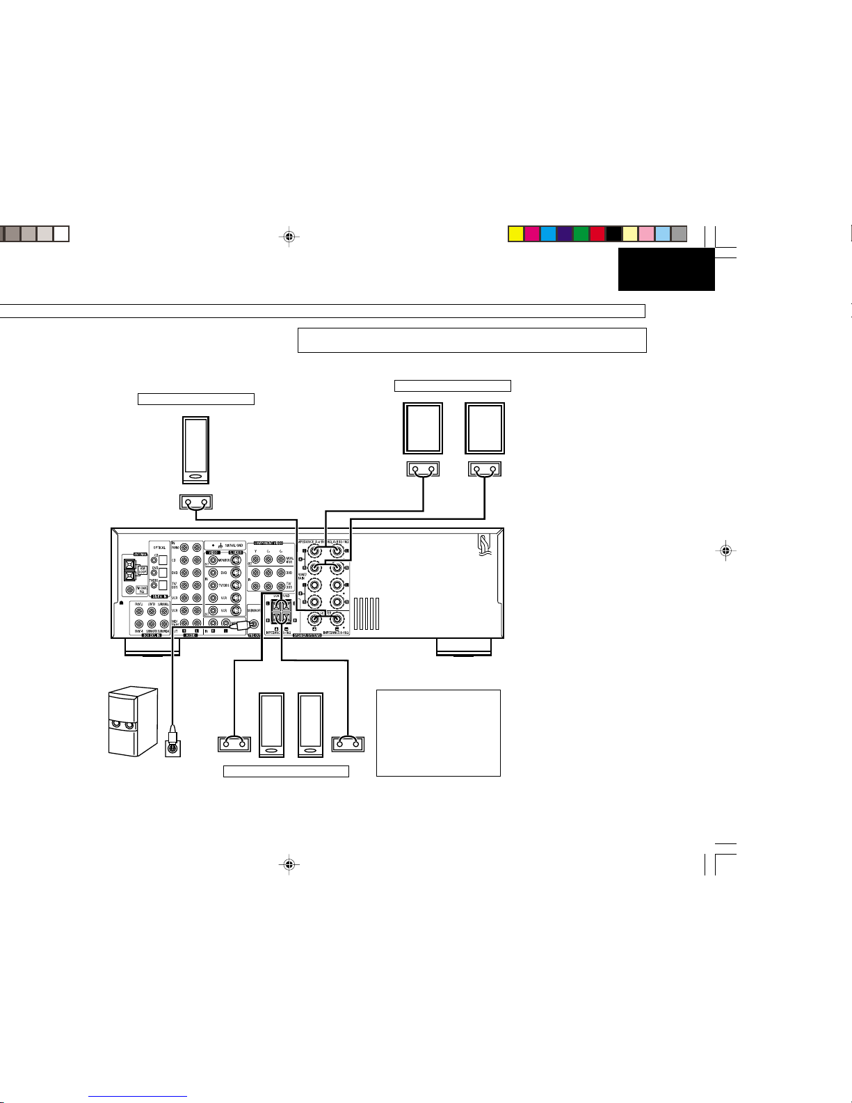
•Connections ..........................................3~6
•Part Names and Functions ....................... 6
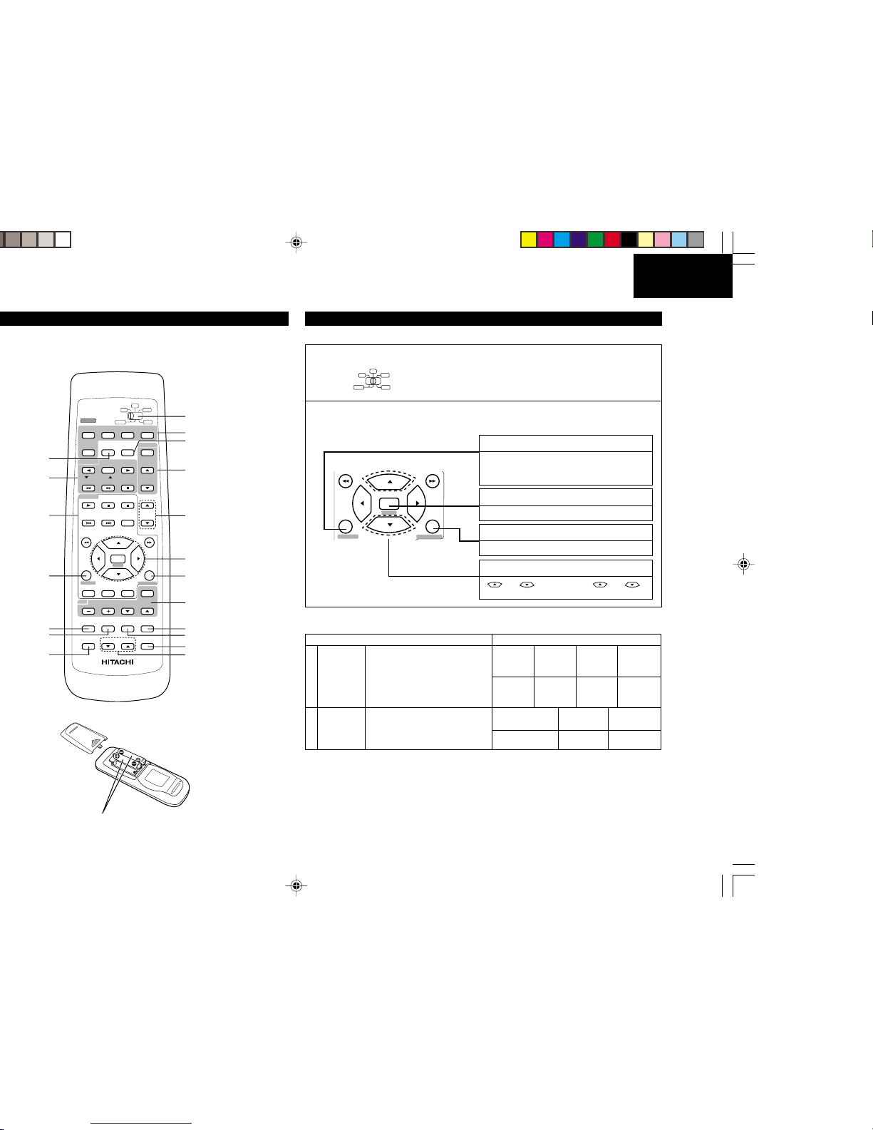
•Remote Control Unit ................................. 7
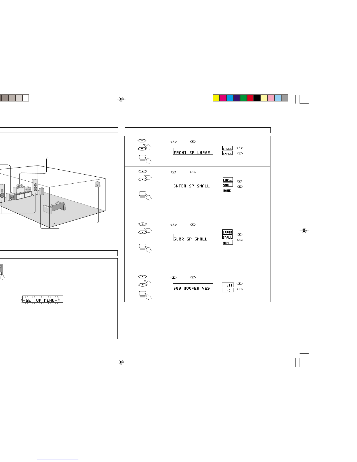
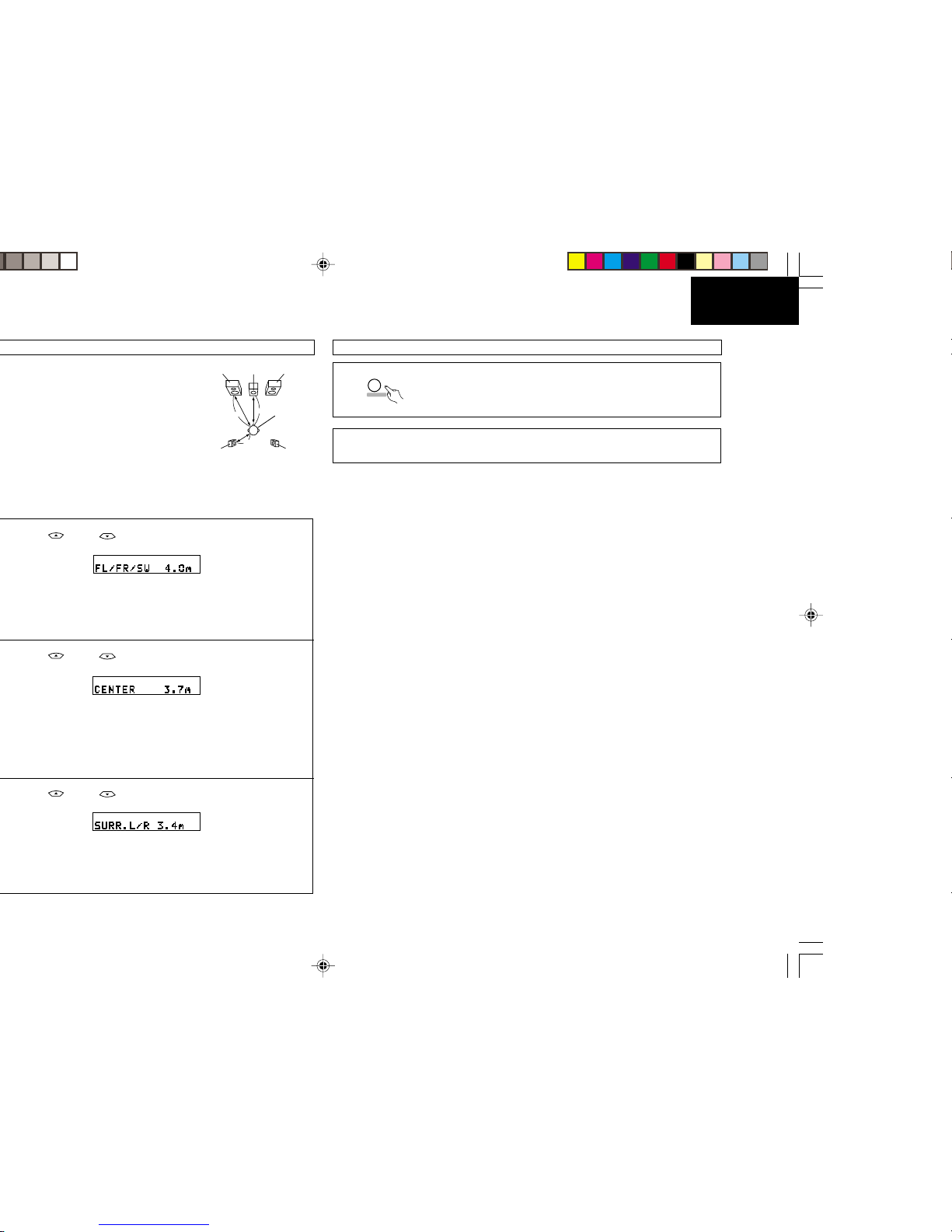
•Setting up the System ......................... 7~11
•Operations ........................................ 11~13
•Using the Surround Function ............ 13~18
•Listening to the Radio ....................... 19~22
•Last Function Memory ............................ 22
•Initialization of the Microprocessor.......... 22
•Troubleshooting ...................................... 23
•Specifications .......................................... 24
•CAUTIONS ON INSTALLATION
•ACCESSORIES
+-
+-
DOLBY
DIGITAL
*
*
10 cm or more
Wall
LDECLARATION OF CONFORMITY
We declare under our sole responsibility that this product, to which this declaration relates,
is in conformity with the following standards:
EN60065, EN55013, EN55020, EN61000-3-2 and EN61000-3-3.
Following the provisions of 73/23/EEC, 89/336/EEC and 93/68/EEC Directive.
LSAFETY PRECAUTIONS
•The POWER button on the front panel and remote control switches the unit from ON to
STANDBY but does not isolate the unit from the mains supply. If it is to be left unattended for
a long period of time, it is recommended that the unit is switched to standby and the mains
plug is removed from the socket.
•Check that all connections are proper and that there are no problems with the connection
cords. Always set the power to standby mode before connecting and disconnecting
connection cords.
•If no sound is emitted from the speakers when the POWER is ON, turn down the MASTER
VOLUME control and press the POWER button to switch the unit to standby mode.Then,
check if the speaker cords are properly connected.
•To prevent short circuits or damaged wires in the connection cords, always unplug the power
cord and disconnect the connection cords between all other audio components when moving
the unit.
•This unit contains a muting circuit and it takes about 5 –6 seconds for this unit to reach
stable operation after switching the set to POWER ON mode.
•Never open the covers or touch the insides or insert a metal object. Any of these could cause
an electric shock or a fault.
•When an electrical storm is present, unplug the power cord and disconnect the antenna
connections.
•The apparatus should not be exposed to dripping or splashing.
•To clean the cabinets and panels when dirty, clean off dirt on the surfaces with a soft, dry
cloth. Never use thinner, benzene or alcohol, as these will damage the surface finish.
•Protect the unit against excessive heat (e.g. direct sunlight), dust and moisture.
•Be careful not to damage the power supply cord. Be sure to hold the plug when pulling it out;
do not pull the cord.
•Do not install the set in a confined location; otherwise, heat dissipation will be poor and
malfunctions may occur.
SAFEGUARDS
Electrical energy can perform many useful functions.This unit has been engineered and
manufactured to assure your personal safety. Improper use can result in potential
electrical shock or fire hazards. In order not to defeat the safeguards, observe the
following instructions for its installation, use and servicing.
LNOTES
•SWITCHING THE INPUT FUNCTIONWHEN INPUT JACKS ARE NOT CONNECTED
A clicking noise may be produced if the input function is switched when nothing is connected to
the input jacks. If this happens, either turn down the MASTER VOLUME control or connect
components to the input jacks.
•MUTING OF PRE OUT JACKS
The PRE OUT jacks include a muting circuit. Because of this, the output signals are greatly
reduced for several seconds after the power operation switch is turned on or input function,
surround mode or any other set-up is changed.
If the volume is turned up during this time, the output will be very high after the muting circuit
stops functioning. Always wait until the muting circuit turns off before adjusting the volume.
Check that the following parts are included in addition to the main unit HTA-DD3E:
•Instruction manual...............................................................................................................1
•Remote control unit (RB-DD1) ...........................................................................................1
•R6P/AA Batteries ................................................................................................................2
•AM loop antenna .................................................................................................................1
•FM indoor antenna..............................................................................................................1
*
*
*
•Always install this unit horizontally.
•For proper heat dissipation, leave at least 10 cm of space between the top, back and sides
of this unit and the wall or other components.
10 cm or more
*1_002-006 HTA-DD3E_EN 7/29/02, 3:40 PM2

3
ENGLISH
Connecting the audio components
•Do not plug in the power cord until all connections have been completed.
•Be sure to connect the left and right channels properly (left with left, right with right).
•Insert the plugs securely. Incomplete connections will result in the generation of noise.
•Note that binding pin plug cords together with power cords or placing them near a power transformer will
result in generating hum or other noise.
•Noiseorhummingmaybegeneratedifaconnectedaudioequipmentis used independently without turning
the power of this unit on. If this happens, turn on the power of the unit.
RL
INPUT RL
OUTPUT RL
OUTPUT
PRE OUT jack
OPITCAL
Turntable (MM cartridge)
Decoders with 6-channel
analog outputs, etc.
LINE OUT
SURROUND
FRONT
SUB WOOFER
CENTER
LINE IN
Tape deck or MD
LINE OUT
Ground wire
LINE OUT
CD player
AC CORD
AC 230 V, 50 Hz
•CONNECTIONS
AM LOOP
ANTENNA
(An Accessory)
DIRECTION OF
BROADCASTING
STATION
FM ANTENNA
75 Ω/ohms
COAXIAL
CABLE
FM INDOOR ANTENNA
(An Accessory)
Connect the internal amplifier’s
subwoofertothesubwooferterminal.
(Refer to page 5. )
Connecting the antenna terminals
PRE OUT jacks
DIGITAL OUT
*1_002-006 HTA-DD3E_EN 7/29/02, 3:40 PM3

4
ENGLISH
Connecting the video equipments
VIDEO
IN
R L OUT IN
S VIDEO
OUT IN
AUDIOAUDIO
OUT
RL
AUDIO
RYCBCR
L
OUT AUDIO DIGITAL
OUT
OPTICAL
VIDEO
OUT S VIDEO
OUT COMPONENT VIDEO
OUT YCBCR
VIDEO
IN S VIDEO
IN COMPONENT VIDEO
IN
AUDIO
RYCBCR
L
OUT AUDIO DIGITAL
OUT
OPTICAL
VIDEO
OUT S VIDEO
OUT COMPONENT VIDEO
OUT
MONITOR OUT
•Connect theTV’s video input jack
(VIDEO INPUT) to the VIDEO
MONITOR OUT jack using a 75
Ω/ohms video coaxial pin plug
cord.
DVD player
TV or DBS tuner output
Video deck
AUDIO IN
AUDIO OUT
VIDEO OUT
AUDIO OUT
VIDEO OUT
VIDEO IN
NOTE
Pleaseconnectto either theVIDEO IN/OUT, SVIDEOIN/OUTorCOMPONENTVIDEO
IN/OUT terminal, depending on your video component.
The signal from the VIDEO IN, S VIDEO IN and COMPONENT VIDEO IN terminals
comesfromtheVIDEOOUT, SVIDEO OUT and COMPONENTVIDEO OUT terminals
respectively. For example, the signal from the VIDEO IN terminal does not come from
the S VIDEO OUT or COMPONENT VIDEO OUT terminals.
S VIDEO OUT
S VIDEO IN
SVIDEO OUT
COMPONENT VIDEO OUT
AUDIO DIGITAL OUT
VIDEO OUT
AUDIO OUT
S VIDEO OUT
COMPONENT
VIDEO OUT
AUDIO DIGITAL OUT
VIDEO IN
S VIDEO IN
COMPONENT VIDEO IN
Monitor TV input
*1_002-006 HTA-DD3E_EN 7/29/02, 3:40 PM4

5
ENGLISH
Speaker system connections
Speaker impedance
•When speaker systems A and B are used separately, speakers with an impedance of 6 to 16 Ω/ohms can be
connected for use as front speakers.
•Be careful when using two pairs of front speakers (A + B) at the same time, since use of speakers with an
impedance of 12 to 16 Ω/ohms.
•Speakers with an impedance of 6 to 16 Ω/ohms can be connected for use as center and surround speakers.
NOTE:
NEVER touch the speaker terminals when the power is on.Doing so could result in electric shocks.
+_
+_
+_
(L) (R)
(L) (R)
+_
+_
CENTER SPEAKER SYSTEM
FRONT SPEAKER SYSTEMS
System A
SURROUND SPEAKER SYSTEMS
•Precautions when connecting
speakers
If a speaker is placed near a TV
orvideo monitor,the colorsonthe
screen may be disturbed by the
speaker’s magnetism. If this
should happen, move the
speakerawayto a position where
it does not have this effect.
Connection jack for subwoofer with
built-in amplifier (super woofer), etc.
*1_002-006 HTA-DD3E_EN 7/29/02, 3:40 PM5

6
ENGLISH
NOTE
•Protector circuit
This unit is equipped with a high–speed protection circuit.The purpose of this circuit is to protect the
speakers under circumstances such as when the output of the power amplifier is inadvertently short-
circuited and a large current flows, when the temperature surrounding the unit becomes unusually
high,orwhentheunitisusedathighoutputovera long period which results in an extremetemperature
rise.
When the protection circuit is activated, the speaker output is cut off and the power supply indicator
LED flashes.Should this occur, please follow these steps:be sure to switch off the power of this unit,
check whether there are any faults with the wiring of the speaker cables or input cables, and wait for
the unit to cool down if it is very hot. Improve the ventilation condition around the unit and switch the
power back on.
If the protection circuit is activated again even though there are no problems with the wiring or the
ventilation around the unit, switch off the power and contact a HITACHI service center.
•Note on speaker impedance
The protector circuit may be activated if the set is played for long periods of time at high volumes when
speakers with an impedance lower than the specified impedance (for example speakers with an
impedance of lower than 4 Ω/ohms) are connected. If the protector circuit is activated, the speaker
output is cut off.Turn off the set’s power, wait for the set to cool down, improve the ventilation around
the set, then turn the power back on.
Front Panel
1. Power operation switch
2. Headphones jack (PHONES)
3. Front SPEAKER A/B buttons
4. TUNING UP/DOWN buttons
5. MEMORY button
6. MODE button
7. BAND button
8. PTY button
9. RT button
10. RDS button
11. DOLBY/DTS SURROUND button
12. DSP SIMULATION button
13. MULTI STEREO button
14. 6CH external input button (6 CH EXT. IN)
15. STEREO button
16. INPUT MODE selector button
17. Preset memory selector buttons
18. Remote control sensor (REMOTE SENSOR)
19. Power indicator (ON/STANDBY)
20. Display
21. Master volume indicator (VOLUME LEVEL)
22. DOLBY digital input indicator
23. Digital lock indicator (LOCK)
24. DTS input indicator
25. Input source selector buttons
26. TREBLE adjustment control
27. BASS adjustment control
28. MASTER VOLUME control
AVSURROUND RECEIVER
HTA-DD3
REMOTE
SENSOR
DOWN CH
OFFON
AB
UP GROUP CDDVD TUNER VCRTV/DBS MD/TAPEMON PHONO
ON/STANDBY
ON / STANDBY
PHONES
SPEAKER
TUNER
UPDOWN MEMORY MODE DOLBY/DTS
SURROUND 6CH
EXT.IN
MULTI
STEREO
DSP
SIMULATION STEREO
BASS
TREBLE MASTER VOLUME
VOLUME LEVEL
+-
INPUT MODE
BAND
TUNING
SURROUND MODE
+-
DIGITAL DTS
LOCK
OFF
17 18 19 20 21 222324 25 26 27 28
16151413121110987654321
DOLBY
DIGITAL
RDSPTY RT
Radio
•PART NAMES AND FUNCTIONS
*1_002-006 HTA-DD3E_EN 7/29/02, 3:40 PM6

7
ENGLISH
ENTER
SET UP
SYSTEM SURROUND
NEXT
•REMOTE CONTROL UNIT
FUNCTION selector button
System buttons (TAPE, VCR)
SYSTEM (SYSTEM SET UP) button
Test tone button
Surround mode selector button
Channel select button
System buttons
(CD, MD, DVD)
MD DVD
DVDTV
A/B
HTA
MD/TAPE
TAPE / VCR
CD/MD/DVD
FUNCTION MD/
TAPE MON
POWER
VCR
VCR
TAPE
CD
PRESET
GROUP
CHANNEL
CHANNEL
DISPLAY
ENTER
SET UP
SYSTEM SURROUND
TV INPUT
VOLUMECHANNEL
T.TONE
CH SELECT
VIDEO SELECT
STATUS
SURR.MODE
REMOTE CONTROLLER
RB - DD1
MUTING
CH VCL
TV
AUDIO TITLE MENU
NEXT
MASTER
VOL
Mode selector switch
POWER buttons
MD/TAPE MONITOR button
Preset memory select buttons
SURROUND
(surround parameter) button
MASTER VOLUME control
buttons
System buttons (TV)
MUTING button
STATUS button
CHANNEL VOLUME UP/
DOWN buttons
Cursor buttons
NEXT button
VIDEO SELECT button
•These settings are required to set up the listening room’s AV system centered around the unit.
1Set the slide switch to “CD”or “MD”.
2Use the following buttons to set up the system:
MD DVD
VCRTAPE
CD
•System setup items and default values (set upon shipment from the factory)
System setup Default settings
1
2
Speaker
Configuration
Delay Time
Input the combination of speakers in your
system and their corresponding sizes
(SMALL for regular speakers, LARGE for
full-size,full-range)to automatically set the
compositionof the signals output from the
speakers and the frequency response.
Thisparameter is foroptimizing the timing
withwhich the audiosignals are produced
from the speakers and subwoofer
according to the listening position.
Front Sp.
Large
Center Sp.
Small
Surround Sp.
Small
Sub Woofer
Yes
Front & SubWoofer
3.7 m
Center
3.7 m
Surround
3.1 m
•
Playback with the above setting is possible upon shipment from the factory and after initializing (refer to page 22).
•SETTING UPTHE SYSTEM
1.5V X 2 [IEC R6, "AA", JIS R6P (JIS SUM-3)]
BATTERY INSERTION
•
The remote control unit will operate from a direct distance of approximately 7 meters, but this distance
will be shortened if obstacles are present or if operated at an angle.
(The remote control unit will operate at
an angle of up to 30°in either direction.)
SYSTEM (SYSTEM SET UP) button
Press this to display the system setup menu.
Also use this button to finish the setting on
the display.
NEXT button
Press this to switch the items.
SURROUND (surround parameter) button
Pressthisto displaythesurroundparameter menu.
CURSOR buttons
and : Use the cursor ( and )
buttons to select the settings.
*1_007-010 HTA-DD3E_EN 7/29/02, 3:41 PM7

8
ENGLISH
Subwoofer Center speaker system
Front speaker systems
Set these at the sides of the TV or screen
with their front surfaces as flush with the
front of the screen as possible. Surround speaker systems
1 Check that all the components are correct, then press the POWER operation
switch on the main unit or the POWER button on the remote control unit to turn on
the power.
2 Press the SYSTEM button to enter the setting.
3 Press the NEXT button to switch to the speaker configuration set up.
NOTE:
Press the SYSTEM button again to finish system set up. System set up can be finished at any time. The
changes to the settings made up to that point are entered.
ON / STANDBY
OFF
HTA
POWER
Before setting up the system
SET UP
SYSTEM
NEXT
Setting the speaker configuration
1 Use the (up) and (down) buttons to select your front speaker parameter.
Press the NEXT button to switch to the center speaker setting.
2 Use the (up) and (down) buttons to select your center speaker
parameter.
Press the NEXT button to switch to the surround speaker setting.
NOTES:
•When “Small”has been selected for the front speakers, “Large”cannot be selected for the center speaker.
•“None”cannot be selected for both the center speaker and surround speakers simultaneously.
•STEREO mode does not have this setting.
3Use the (up) and (down) buttons to select your surround speaker
parameter.
Press the NEXT button to switch to the subwoofer setting.
NOTES:
•When“Small”hasbeen selected for the front speakers, “Large”cannotbeselected for the surround speakers.
•When“None”has beenselectedforthe center speaker,“None”cannot be selected forthe surround speakers.
•STEREO mode does not have this setting.
4Use the (up) and (down) buttons to select your subwoofer setting.
Press the NEXT button to enter the settings and switch to the DELAY TIME setting.
LParameters
Large ...... Select this when using speakers that can fully reproduce low sounds of below 80 Hz.
Small ...... Select this when using speakers that cannot reproduce low sounds of below 80 Hz with sufficient
volume.When this setting is selected, low frequencies of below 80 Hz are assigned to the subwoofer.
None ...... Select this when no speakers are installed.
Yes/No.... Select “Yes”when a subwoofer is installed, “No”when it’s not installed.
NOTE:
Select “Large”or “Small”not according to the physical size of the speaker, but according to the bass reproduction
capacity at 80 Hz. If you cannot determine the best setting, try comparing the sound when set to “Small”and when
set to “Large”, at a level that will not damage the speakers.
(up) button
(down) button
[[
[[
[
[[
[[
[
(up) button
(down) button
[[
[[
[
[[
[[
[
(up) button
(down) button
[[
[[
[
[[
[[
[
(up) button
(down) button
[[
[[
[
[[
[[
[
NEXT
NEXT
NEXT
NEXT
Speaker system layout
Basic system layout
•Thefollowingis an exampleof the basic layoutfora system consisting of six speakersystems and a television
monitor:
*1_007-010 HTA-DD3E_EN 7/29/02, 3:41 PM8

9
ENGLISH
Setting the delay time
Input the distances from the listening position to the speakers and set the surround
delay time.
Preparations:
Measure the distances from the listening position to the speakers (L1 to L3 on the
diagram at the right).
L1: Distance from center speaker to listening position
L2: Distance from front speakers to listening position
L3: Distance from surround speaker to listening position
NOTES:
•Set the center speaker at the same distance from the front speakers (left and right) or the subwoofer, or so that
the difference in distance (L2 –L1) is 1.5 meters or less.
•Set the surround speakers (left and right) at the same distance from the front speakers (left and right) or the
subwoofer, or so that the difference in distance (L2 –L3) is 4.5 meters or less.
1 Use the (up) and (down) buttons to set the distance from the front
speakers and the subwoofer to the listening position.
•The number changes in units of 0.3 metres each time one of the buttons is
pressed. Select the value closest to the measured distance.
(“SW”appears only when subwoofer = yes.)
Press the NEXT button to switch to the center speaker setting.
2 Use the (up) and (down) buttons to set the distance from the center
speakers to the listening position.
•The number changes in units of 0.3 metres each time one of the buttons is
pressed. Select the value closest to the measured distance.
Press the NEXT button to switch to the surround speaker setting.
NOTE:
•No setting when “None”has been selected for the center speaker.
3 Use the (up) and (down) buttons to set the distance from the surround
speakers to the listening position.
•The number changes in units of 0.3 metres each time one of the buttons is
pressed. Select the value closest to the measured distance.
NOTE:
•No setting when “None”has been selected for the surround speakers.
NEXT
NEXT
L2L1
L3
FL
SL SR
FR
C
Listening
position
After setting up the system
1 Press the SYSTEM button to finish system set up.
This completes the system setup operations.Once the system is set up, there is no need to make the settings
again unless other components or speakers are connected or the speaker layout is changed.
SET UP
SYSTEM
*1_007-010 HTA-DD3E_EN 7/29/02, 3:41 PM9

10
ENGLISH
Operating Audio/Video components stored in the preset memory
Audio/Video components stored in the preset can be controlled using this
unit’s remote control unit.
Note that some components Audio/Video components stored in the preset
memory, however, cannot be operated with this remote control unit.
1Set the slide switch to the position for the component to be
operated.
2Use the buttons shown below to operate the audio component.
For details, refer to the respective component’s manual.
a. For DVD player
b. For CD player and MD player
c. For tape deck and VCR
d. ForTV
MD DVD
DVDTV
A/B
HTA
MD/TAPE
TAPE/ VCR
CD/MD/DVD
FUNCTION MD/
TAPEMON
POWER
VCR
VCR
TAP E
CD
PRESET
GROUP
CHANNEL
CHANNEL
DISPLAY
ENTER
SET UP
SYSTEM SURROUND
TV INPUT
VOLUMECHANNEL
T.TON E
CH SELECT
VIDEO SELECT
STATUS
SURR.MODE
REMOTE CONTROLLER
RB - DD1
MUTING
CH VCL
TV
AUDIO TITLE MENU
NEXT
MASTER
VOL
2-b
2-c
2-a
2-d
1
MD DVD
VCRTAPE
CD
POWER : Power on/off
1
: Play
3
: Pause
2: Stop
8,9
: Auto search
6,7
: Reverse/Forward
•
,
ª
,0,1
: Cursor up/down/
left/right
DISPLAY
ENTER
SET UP
RETURN
AUDIO
TITLE
MENU
POWER
: Power on/off
1
: Play
3
: Pause
2: Stop
8,9
: Skip
6,7
: Manual search
POWER
: Power on/off
0
: Reverse play (tape)
A/B
: A/B deck selection
(tape)
1
: Forward play (tape)
Play (VCR)
6,7
: Reverse/Forward
2: Stop
•CHANNEL ª
: Channel up/down
(VCR)
POWER
: Power on/off
CHANNEL
: Channel
+,–
up/down
VOLUME
: TV volume
•
,
ª
up/down
TV INPUT
: TV input
NOTE:
•The tuner can be operated when the switch is at any position.
Preset Memory
HITACHI and other makes of components can be operated by setting the preset memory for your make of video component.
Operation is not possible for some models.
1Set the slide switch to the desired component.
2Holding in the POWER button of the components
(DVD, MD, TAPE, VCR or TV) you want to set,
press the button for the corresponding manufacturer
in block A. (Refer to Table 1.)
3Next, while holding in the POWER button, press the
button for the code in block B.(Refer to Table 1.)
4To continue registering other components, repeat
steps 1 to 3.
NOTE:
This remote control unit can only operate HITACHI's CD player at CD position.
Table 1: Combinations of Personal System Codes for Different Manufacturers
“DVD”“MD”
MD DVD
VCRTAPE
CD
PRESET GROUP
TAPE
TAPE
A/B
TAPE
PRESET
TAPE
TAPE
TAPE
PRESET
CD
CD
CD
CD
CD
DISPLAY
CH SELECT
(
a
) CH VOL DOWN
(
b
) CH VOL UP
(
c
)
HITACHI
DENON A
–
–
PANASONIC
–
JVC
SHARP
SONY
PIONEER
TOSHIBA
–
–
–
–
–
DENON B
–
–
–
–
–
–
–
–
–
–
–
–
–
–
–
–
–
–
–
–
–
–
–
–
–
–
–
–
–
DENON
–
–
–
SHARP
–
SONY
–
PIONEER
–
KENWOOD
–
–
–
–
–
–
–
–
–
–
–
–
–
–
–
–
–
–
–
–
–
–
–
–
–
–
–
–
–
–
–
–
–
NOTES:
•The memory can only be preset for either the MD or the TAPE.
•Preset codes set upon shipment from the factory and when reset.
CD/MD/DVD
DISPLAY
ENTER
SET UP
SYSTEM SURROUND
TV INPUT
AUDIO TITLE MENU
NEXT
MASTER
VOL
MD DVD
DVDTV
A/B
HTA
MD/TAPE
TAPE/ VCR
CD/MD/DVD
FUNCTION MD/
TAPEMON
POWER
VCR
VCR
TAPE
CD
PRESET
GROUP
CHANNEL
CHANNEL
DISPLAY
ENTER
SET UP
SYSTEM SURROUND
TV INPUT
VOLUMECHANNEL
T.TONE
CH SELECT
VIDEO SELECT
STATUS
SURR.MODE
REMOTE CONTROLLER
RB - DD1
MUTING
CH VCL
TV
AUDIO TITLE MENU
NEXT
MASTER
VOL
1
2
A
B
CD/MD/DVD
DISPLAY
ENTER
SET UP NEXT
MASTER
VOL
A/B
MD/TAPE
TAPE / VCR
CD/MD/DVD
FUNCTION MD/
TAPE MON PRESET
GROUP
CHANNEL
CHANNEL
SYSTEM SURROUND
TV INPUT
VOLUMECHANNEL
T.TONE VIDEO SELECTSURR.MODE MUTING
TV
AUDIO TITLE MENU
B
ACH SELECT
(
a
) CH VOL DOWN
(
b
) CH VOL UP
(
c
)
B
A
PRESET GROUP
TAPE
TAPE
A/B
TAPE
PRESET
TAPE
TAPE
TAPE
PRESET
CD
CD
CD
CD
CD
DISPLAY
*1_007-010 HTA-DD3E_EN 7/29/02, 3:41 PM10

11
ENGLISH
“VCR”“TV”
HITACHI A
–
MITSUBISHI A
PANASONIC A
JVC A
SONY A
PIONEER
TOSHIBA A
SANYO A
SHARP A
NEC A
PHILIPS A
RCA A
GENERAL ELE. A
MAGNAVOX A
HITACHI B
–
MITSUBISHI B
PANASONIC B
JVC B
SONY B
–
TOSHIBA B
SANYO B
SHARP B
NEC B
PHILIPS B
RCA B
GENERAL ELE. B
MAGNAVOX B
–
–
MITSUBISHI C
PANASONIC C
JVC C
SONY C
–
–
–
–
NEC C
PHILIPS C
–
–
MAGNAVOX C
HITACHI
–
MITSUBISHI A
PANASONIC A
JVC
SONY
PIONEER
TOSHIBA
SANYO
SHARP
NEC
PHILIPS
RCA
GENERAL ELE. A
MAGNAVOX
–
–
MITSUBISHI B
PANASONIC B
–
–
–
–
–
–
–
–
–
GENERAL ELE. B
–
–
–
–
–
–
–
–
–
–
–
–
–
–
–
–
“TAPE”
–
–
DENON
–
JVC A
–
SONY A
–
PIONEER A
–
KENWOOD A
–
–
–
–
–
–
–
–
JVC B
–
SONY B
–
PIONEER B
–
KENWOOD B
–
–
–
–
–
–
–
–
JVC C
–
–
–
–
–
KENWOOD C
–
–
–
–
•Preset codes set upon shipment from the
factory and when reset.
NOTES:
•The signals for the pressed buttons are emitted
while setting the preset memory. To avoid
accidental operation, cover the remote control
unit’s transmitting windowwhile setting the preset
memory.
•Some models and years of manufacturer of
components of the manufacturers listed on Table
1 cannot be used.
•The unit is equipped with several types of remote
controlcodeswhichdepend on the manufacturer.
If there is no operation when set to a, please
change the setting to bor cand try again.
Before operating
Preparations:
Check that all connections are proper.
1Set to the center position.
2Turn on the power.
Press the power operation switch (button).
•ON/STANDBY
When the button is pressed, the power turns
on and the display lights after approximately 1
second.When pressed again, the power turns
off, the standby mode is set and the display
turns off. Several seconds are required from
the time the power switch is set to the “ON”
position until sound is output. This is due to
the built-in muting circuit that prevents noise
when the power switch is turned on and off.
3Select the front speakers.
Press the SPEAKER A or B button to turn
the speaker on.
BASS TREBLE
++
ON
SPEAKER
AB
+-
+-
2
3
1
DOLBY
DIGITAL
MD DVD
DVDTV
A/B
HTA
MD/TAPE
TAPE/ VCR
CD/MD/DVD
FUNCTION MD/
TAPEMON
POWER
VCR
VCR
TAPE
CD
PRESET
GROUP
CHANNEL
CHANNEL
2
•OPERATIONS
ON / STANDBY
OFF
HTA
POWER
CH SELECT
(
a
) CH VOL DOWN
(
b
) CH VOL UP
(
c
)
B
ACH SELECT
(
a
) CH VOL DOWN
(
b
) CH VOL UP
(
c
)
B
A
CH SELECT
(
a
) CH VOL DOWN
(
b
) CH VOL UP
(
c
)
B
A
PRESET GROUP
TAPE
TAPE
A/B
TAPE
PRESET
TAPE
TAPE
TAPE
PRESET
CD
CD
CD
CD
CD
DISPLAY
PRESET GROUP
TAPE
TAPE
A/B
TAPE
PRESET
TAPE
TAPE
TAPE
PRESET
CD
CD
CD
CD
CD
DISPLAY
PRESET GROUP
TAPE
TAPE
A/B
TAPE
PRESET
TAPE
TAPE
TAPE
PRESET
CD
CD
CD
CD
CD
DISPLAY
*1_011-018 HTA-DD3E_EN 7/29/02, 3:41 PM11

12
ENGLISH
Playing the analog program source
1Press the button for the program source to be
played.
EX 1: CD
or press the FUNCTION button repeatedly until
the desired source (CD) appears on the display.
The function switches in the following order each
time the FUNCTION button is pressed:
EX 2: MD/TAPE
•Press the button once to switch the source to
MD/TAPE input, again to cancel MD/TAPE
input.
2Select the ANALOG input mode.
Check that the “ANALOG”indicator is lit.
3Start playback on the selected component.
For operating instructions, refer to the various
components manuals.
4Adjust the MASTER VOLUME control.
•The volume can be adjusted in units of 1dB
from -60 to 0 to 18 dB.
5Adjust the BASS and TREBLE.
Turn the control clockwise to increase the bass
or treble, counterclockwise to decrease it.
Lights
CD
FUNCTION
MD/TAPE MON
MD/
TAPE MON
INPUT MODE
ANALOG
MAINVOLUME
MASTER
VOL
The volume is indicated
on the set’s display.
BASS TREBLE
++
1
4
1
2
+-
+-
DOLBY
DIGITAL
45
MD DVD
DVDTV
A/B
HTA
MD/TAPE
TAPE/ VCR
CD/MD/DVD
FUNCTION MD/
TAPEMON
POWER
VCR
VCR
TAPE
CD
PRESET
GROUP
CHANNEL
CHANNEL
DISPLAY
ENTER
SET UP
SYSTEM SURROUND
TV INPUT
VOLUMECHANNEL
T.TONE
CH SELECT
VIDEO SELECT
STATUS
SURR.MODE
REMOTE CONTROLLER
RB - DD1
MUTING
CH VCL
TV
AUDIO TITLE MENU
NEXT
MASTER
VOL
Playing the digital program source
2Select the DIGITAL input mode.
3Check that the “DIGITAL”indicator is lit.
When digital signals are input properly, the
“LOCK”indicator is lit.
*
If the “LOCK”indicator is not lit, check that
the system setup’s input setting (refer to
page 7) and the connections are proper,
that the component’s power is turned on, etc.
* It is not possible to switch to the digital input
mode if input sources do not have digital
setting.
4Start playback on the selected component.
For operating instructions, refer to the various
components’manuals.
5Adjust the MASTER VOLUME control.
NOTES:
•NEVER try to play CD-ROM discs.
•If a CD-ROM is played, the “LOCK”indicator
is lit but no sound is heard.
DIGITAL
Light on Light on
LOCK
1Press the button for the program source to
be played that is connected to the digital
input jacks.
EX: DVD
MAINVOLUME
MASTER
VOL
+-
+-
135
2
DOLBY
DIGITAL
A/B
MD/TAPE
TAPE/ VCR
CD/MD/DVD
FUNCTION MD/
TAPEMON PRESET
GROUP
CHANNEL
CHANNEL
DISPLAY
ENTER
SET UP
SYSTEM SURROUND
TV INPUT
AUDIO TITLE MENU
NEXT
MASTER
VOL
1
5
DVD
FUNCTION
Simulcast playback
The video source switches as follows each time the VIDEO SELECT button is pressed:
1Press the VIDEO SELECT button repeatedly until the desired source appears on the display.
Use this switch to monitor a video source other than the audio source.
VIDEO SELECT
T.TONE
CH SELECT
VIDEO SELECT
STATUS
SURR.MODE
REMOTE CONTROLLER
RB - DD1
MUTING
CH VCL
1
INPUT MODE
TUNER DVD
CD PHONO VCR
TV/DBS
VIDEO = DVD VIDEO = TV/DBS
VIDEO = OFF
VIDEO = VCR
*1_011-018 HTA-DD3E_EN 7/29/02, 3:41 PM12

13
ENGLISH
Using the muting function Listen with headphones
1Press the MUTING button.
•Cancelling MUTING mode.
Press the MUTING button
again.
•Caution:
Switching off the power of the unit and the remote
control unit will cancel the settings.
1Connect the headphones
to the headphones jack of
the front panel.
2Press the SPEAKER A or
B button to turn the
speaker off.
Use this to turn off the audio output temporarily.
MUTING
T.TONE
CH SELECT
VIDEO SELECT
STATUS
SURR.MODE
REMOTECONTROLLER
RB - DD1
MUTING
CH VCL
1
PHONES
ON
SPEAKER
AB
Front panel display
1Press the STATUS button.
•The input and output sources and the surround setting, etc., appear in order on the display each time
the button is pressed.
When an operation is performed on the remote control unit, that operation appears on the display, making it
possible to check the operation visually.
The set’s operating status can also be checked on the display using the procedure described below.
STATUS
CH SELECT STATUS
REMOTE CONTROLLER
RB - DD1
CH VCL
1
Recording the program source
(recording the source currently being monitored)
1Follow steps 1 to 3 under“Playing the analog
program source”.2Start recording on the tape or video deck.
For instructions, refer to the component’s
operating instructions.
Simultaneous recording
The signals of the source selected with the function selector button are output simultaneously to the MD/
TAPE OUT and VCR REC OUT jacks.
If a total of two tape and/or video decks are connected and set to the recording mode, the same source can
be recorded simultaneously on each deck.
In addition, if the TAPE MONITOR (MD/TAPE MON) button is pressed, the audio signals from the tape deck
are output to the VCR AUDIO REC OUT jacks.
2Tape monitor function
When a three-head tape deck is used, the sound actually being recorded can be monitored during recording by
pressing the MD/TAPE MON button.
Press the button again to cancel monitoring.
NOTE :
•Digital input signals cannot be recorded.To record, connect to the analog input terminals.
Before playing with the surround function
Before playing with the surround function, be sure to use the test tones to adjust the playback level from the
different speakers.
This adjustment can be performed with the remote control unit, as described below.
Adjusting with the remote control unit using the test tones is only effective in the DOLBY PRO LOGIC, DOLBY
DIGITAL and DTS modes.
The adjusted levels are automatically stored in the memory.
1Set the Dolby Pro Logic, Dolby Digital or
DTS modes.
2Press the test tone button.
3Test tones are produced from
the speakers in the order
shown below, at 4 second in-
tervals for the first two cycles,
2 second intervals after that.
Use the channel volume adjust buttons to
adjust so that the volume of the test tones is
the same for all the speakers.
Pressthechannelselect button
to select the speaker to be
adjusted, if necessary.
4
Aftercompleting the adjustment,
pressthetesttone buttonagain.
1
Pressthe channel select button
to select the speaker to be
adjusted.
2Adjust the level of the selected
speaker.
After adjusting using the test tones, adjust the channel levels either according to the playback sources or to suit
your tastes, as described below.
+-
+-
1
DOLBY
DIGITAL
3
1
2,4
VOLUMECHANNEL
T.TONE
CH SELECT
VIDEO SELECT
STATUS
SURR.MODE
REMOTE CONTROLLER
RB - DD1
MUTING
CH VCL
TV
DOLBY/DTS
SURROUND
SURR.MODE
T.TONE
CH VOL
FL C FR SR SL SW
CH SELECT
T.TONE
CH SELECT
CH VOL
2
1
VOLUMECHANNEL
T.TONE
CH SELECT
VIDEO SELECT
STATUS
SURR.MODE
REMOTE CONTROLLER
RB - DD1
MUTING
CH VCL
TV
•USINGTHE SURROUND FUNCTION
You may enjoy an analog or digital surround system for your connected audio/video source.
*1_011-018 HTA-DD3E_EN 7/29/02, 3:41 PM13

14
ENGLISH
Using surround system with analog input
1Press the button for the program source to be
played.
EX: CD
2Select the ANALOG input mode.
Check that the “ANALOG”indicator lights up.
3Select your preferred playback mode (see table
below).
4Start playback on the selected component. For
operating instructions, refer to the various
components’manuals.
5Check that the indicators for your selected
playback light up.
+-
+-
5
3 2
DOLBY
DIGITAL
1
CD
FUNCTION
INPUT MODE
Input
Mode Playback Mode
To select : Press Display
STEREO
DOLBY/DTS
SURROUND
DSP
SIMULATION
ANALOG
ANALOG
PRO LOGIC
ANALOG
ANALOG
STEREO
PRO LOGIC
DSP
Using surround system with digital input
1Press the button for the program source to be
played.
EX: DVD
2Select the DIGITAL input mode.
Check that the “LOCK”indicator lights up.
3Select your preferred playback mode (see table
below).
4Start playback on the selected component.For
operating instructions, refer to the various
components’manuals.
5Check that the indicators for your selected
playback light up.
DVD
FUNCTION
INPUT MODE
+-
+-
5
3 2
DOLBY
DIGITAL
1
There are 5 types of digital input mode —PCM (2 ch Audio, 32 kHz, 44 kHz, 48 kHz, 96 kHz), DOLBY DIGITAL (2
ch), DOLBY DIGITAL (5.1 ch), DTS (2 ch) (for CD playback only) as well as DTS (6 ch) (for DVD playback only).
However, this unit will automatically detect the input signal of your connected audio/video source.
Input
Mode Playback Mode
To select : Press Display
PCM
(2ch AUDIO)
EX.: CD
STEREO
PRO LOGIC
DSP
Indicators
LOCK
DIGITAL
LOCK
LOCK
PRO LOGIC DIGITAL
DIGITAL
See page 17. See page 17.
STEREO
DOLBY/DTS
SURROUND
DSP
SIMULATION
*1_011-018 HTA-DD3E_EN 7/29/02, 3:41 PM14

15
ENGLISH
Input
Mode Playback Mode
To select : Press Display
DOLBY
DIGITAL
(2 ch)
STEREO
PRO LOGIC
Indicators
LOCK DIGITAL
PRO LOGIC DIGITAL
STEREO
DOLBY DIGITAL
STEREO
STEREO
LOCK
DTS
DIGITAL
LOCK
LOCK
LOCK
DOLBY
DIGITAL
DTS
(CD
playback)
DTS
LOCK DTS
LOCK DTS
DIGITAL
DIGITAL
DIGITAL
DIGITAL
DIGITAL
DIGITAL
DTS
(DVD
playback)
Using the Dolby Pro Logic mode
Play a pre-recorded source with the mark. 1Press the button for the
program source to be
played.
2Set the Dolby surround mode.
3Start playback on the selected component.
For operating instructions, refer to the
various components’manuals.
4Adjust the MASTER VOLUME and TONE
controls.
EX.: VCR
Lit
NOTE:
•Thereare fourDolbySurround ProLogicmodes
(NORMAL, PHANTOM, WIDE and 3CH.
LOGIC) This unit sets the mode automatically
according to the types of speakers set during
the system setup process.
VCR
DOLBY/DTS
SURROUND
SURR.MODE
PRO LOGIC
MAINVOLUME
MASTER
VOL
BASS
+
TREBLE
+
1
4
2
+-
+-
2
14
4
DOLBY
DIGITAL
MD DVD
DVDTV
A/B
HTA
MD/TAPE
TAPE/ VCR
CD/MD/DVD
FUNCTION MD/
TAPEMON
POWER
VCR
VCR
TAPE
CD
PRESET
GROUP
CHANNEL
CHANNEL
DISPLAY
ENTER
SET UP
SYSTEM SURROUND
TV INPUT
VOLUMECHANNEL
T.TONE
CH SELECT
VIDEO SELECT
STATUS
SURR.MODE
REMOTE CONTROLLER
RB - DD1
MUTING
CH VCL
TV
AUDIO TITLE MENU
NEXT
MASTER
VOL
FUNCTION
STEREO
DOLBY/DTS
SURROUND
STEREO
DOLBY/DTS
SURROUND
STEREO
DOLBY/DTS
SURROUND
STEREO
(red)
DIGITAL
DIGITAL
DIGITAL
DTS LOCK DTS
DOLBY/DTS
SURROUND
DIGITAL
(white)
*1_011-018 HTA-DD3E_EN 7/29/02, 3:41 PM15

16
ENGLISH
Using the Dolby Digital mode
1Press the DVD button.
2Select the DIGITAL input mode.
3Set the DOLBY surround mode.
4Start playback on the selected component.
For operating instructions, refer to the
various components’manuals.
•The PRO LOGIC indicator lights when a
2-channel Dolby Digital signal is input.
Play a pre-recorded source (DVD) with the mark.
5Adjust the MASTER VOLUME control.
6Set the slide switch to “CD”or “MD”.
7Set the surround parameter according to the source and adjust the tone.
First press the SURROUND button.
Then press the NEXT button to switch to the various settings as follows.
MD DVD
DVDTV
A/B
HTA
MD/TAPE
TAPE/ VCR
CD/MD/DVD
FUNCTION MD/
TAPEMON
POWER
VCR
VCR
TAPE
CD
PRESET
GROUP
CHANNEL
CHANNEL
DISPLAY
ENTER
SET UP
SYSTEM SURROUND
TV INPUT
VOLUMECHANNEL
T.TONE VIDEOSELECTSURR.MODE MUTING
TV
AUDIO TITLE MENU
NEXT
MASTER
VOL
1
3
5
8,9
7
6
1 5
2
3
+-
+-
DOLBY
DIGITAL
DVD
FUNCTION
INPUT MODE
DOLBY/DTS
SURROUND
SURR.MODE
MAIN VOLUME
MASTER
VOL
MD DVD
VCRTAPE
CD
NEXT
SURROUND
8Use the (up) and (down) buttons to set the D. Comp.
Press the SURROUND button to finish the setting.
Press the NEXT button to switch to the default setting.
9To reset the settings to the factory defaults, use the (up) and (down)
buttons to display “Yes”, then press the SURROUND button twice.
The settings are entered and the surround parameter setting mode is finished.
Press the SURROUND button to finish the setting.
Press the NEXT button to switch to the D. COMP.setting.
2Surround Parameters
D.COMP.(Dynamic Range Compression):
Motion picture soundtracks have tremendous dynamic range (the contrast between very soft and very loud
sounds). For listening late at night, or whenever the maximum sound level is lower than usual, the Dynamic
Range Compression allows you to hear all of the sounds in the soundtrack (but with reduced dynamic range).
(This only works when playing program sources recorded in Dolby Digital) Select one of the four parameters
(“OFF”, “LOW”, “MID”(middle) or “HI”(high)). Set to OFF for normal listening.
NOTE:
•When playing back in the Dolby Pro Logic mode, depending on the settings of each output channel, it may
not be possible to make a setting of the master volume that exceeds 3dB.
(up) button
(down) button
[[
[[
[
[[
[[
[
(up) button
(down) button
[[
[[
[
[[
[[
[
NEXT
SURROUND
NEXT
SURROUND
*1_011-018 HTA-DD3E_EN 7/29/02, 3:41 PM16

17
ENGLISH
1Press the DVD button.
EX.: DVD
2Select the DIGITAL input mode.
3Set the DTS mode.
4Start playback on the selected component. For
operating instructions, refer to the various
component’s manuals.
5Adjust the MASTER VOLUME control.
Using the DTS mode
Play a pre-recorded source with mark.
1
5
3
+-
+-
23
15
DOLBY
DIGITAL
MD DVD
DVDTV
A/B
HTA
MD/TAPE
TAPE/ VCR
CD/MD/DVD
FUNCTION MD/
TAPEMON
POWER
VCR
VCR
TAPE
CD
PRESET
GROUP
CHANNEL
CHANNEL
DISPLAY
ENTER
SET UP
SYSTEM SURROUND
TV INPUT
VOLUMECHANNEL
T.TON E
CH SELECT
VIDEO SELECT
STATUS
SURR.MODE
REMOTE CONTROLLER
RB - DD1
MUTING
CH VCL
TV
AUDIO TITLE MENU
NEXT
MASTER
VOL
DVD
FUNCTION
INPUT MODE
DOLBY/DTS
SURROUND
SURR.MODE
MAIN VOLUME
MASTER
VOL
•Surround modes and their features
•DSP SURROUND SIMULATION
•Thisunitequipped with a high performance DSP (Digital Signal Processor)whichusesdigital signal processing
to synthetically recreate the sound field. One of eight preset surround modes can be selected according to the
program source and the parameters can be adjusted according to the conditions in the listening room to
achieve a more realistic, powerful sound.These surround modes can also be used for program sources not
recorded in Dolby Surround Pro Logic, Dolby Digital or DTS.
1 STEREO Sound is produced from the two front channels. (Nothing is output from
the Surround and center channels.)
2 6CH EXT. IN Connect the output of the external decoder to this unit’s 6CH EXT. IN.
3 MULTI STEREO In this mode, the signals of the front left channel are output from the left
surround channel, the signals of the front right channel are output from
the right surround channel, and the same (in-phase) component of the
left and right channels is output from the center channel. This mode
provides all speaker surround sound, but without directional steering
effects, and works with any stereo program source.
4 MONO MOVIE Select this when watching monaural movies for a greater sense of
expansion.
5 ROCK ARENA Use this mode to achieve the feeling of a live concert in an arena with
reflected sounds coming from all directions.
6 JAZZ CLUB This mode creates the sound field of a live house with a low ceiling and
hard walls.This mode gives jazz a very vivid realism.
7 STADIUM Use this to enjoy stadium effect.
8 MATRIX Select this to emphasize the sense of expansion for music sources
recorded in stereo. Signals consisting of the difference component of
the input signals (the component that provides the sense of expansion)
processed for delay are output from the surround channel.
•Depending on the program source being played, the effect may not be very noticeable.
In this case, try other surround modes, without worrying about their names, to create a sound field suited to
your tastes.
•Thepresenceofsurround parameter settings as wellasthe setting items will differdependingon the surround
mode.
Using the DSP surround simulation
NOTE:
•CDs with the DTS feature require a decoder, so when using the “ANALOG”input mode, a noise may be
produced by the DTS encoded signal. Therefore, before playing the DTS feature, be sure to select the
DIGITAL input mode.
*1_011-018 HTA-DD3E_EN 7/29/02, 3:41 PM17

18
ENGLISH
1Select the surround mode according to the input
source.
The surround mode switches in the following
order each time the DSP SIMULATION button is
pressed:
2Set the surround parameter according to the source and adjust the tone.
First press the SURROUND button.
Then press the NEXT button to switch to the various settings as follows.
•DSP: MATRIX mode [skip to step 5
•DSP: Other modes [step 3
NOTE: Set the slide switch to “CD”or “MD”when setting the surround parameters.
Surround parameters cannot be set whilst in STADIUM mode.
3Use the (up) and (down) buttons to set the room size.
Press the SURROUND button to finish the setting.
Press the NEXT button to switch to the effect level setting.
4Use the (up) and (down) buttons to set the effect level.
Press the SURROUND button to finish the setting.
Press the NEXT button to switch to the default setting (STEP 6).
Preparations: Select the input device and start playback.
(up) button
(down) button
[[
[[
[
[[
[[
[
(up) button
(down) button
[[
[[
[
[[
[[
[
MONO MOVIE ROCK ARENA
MATRIX STADIUM
JAZZ CLUB
SURROUND
NEXT
SURROUND
NEXT
NEXT
+-
+-
1
3,4,5,6
1
2,3,4,5,6
2,3,4,5,6
DOLBY
DIGITAL
ENTER
SET UP
SYSTEM SURROUND
TV INPUT
VOLUMECHANNEL
T.TONE VIDEO SELECTSURR.MODE MUTING
TV
AUDIO TITLE MENU
NEXT
DSP
SIMULATION MULTI
STEREO 6 CH
EXT.IN STEREO
SURR.MODE
5Use the (up) and (down) buttons to set the delay time.
Press the SURROUND button to finish the setting.
Press the NEXT button to switch to the default setting (STEP 6).
6To reset the settings to the factory defaults, use the (up) and
(down) buttons to display “Yes”, then press the SURROUND button twice.
The settings are reset and the surround parameter setting mode is finished.
If there is no need to reset, press the SURROUND button when the above is
displayed or when “NO”has been set to finish the setting.
Press the NEXT button to switch to the room size or delay time setting.
2Surround Parameters
ROOM SIZE ............. “Room size”refers to the size of the sound field. –There are three parameters:
“Small”“Medium”“Large”
EFFECT LEVEL ........ “Effect level”refers to the strength of the effect sounds.If the sound becomes distorted,
lower the level. Parameters “1”~ “15”
DELAY TIME ............. This can be set to between 0 and 150 msec for the MATRIX mode.
NOTES:
•When the mode is switched to Dolby Digital encoded signals while playing PCM digital signals in the surround
modes except STEREO, the mode is forcibly switched to the Dolby Surround mode.
•To listen to the signal of equipment that is connected to the “6CH EXT. IN”input jack, make sure the video
input of the equipment is selecting the connected function and select “6CH EXT. IN”with the “6CH EXT. IN”
mode button or with the remote control mode button.
2Surround modes and parameters
(up) button
(down) button
[[
[[
[
[[
[[
[
(up) button
(down) button
[[
[[
[
[[
[[
[
'
'
'
'
MODE
STEREO
DOLBY PRO LOGIC
DOLBY DIGITAL
DTS
6CH EXT.IN
MULTI STEREO
MONO MOVIE
ROCK ARENA
JAZZ CLUB
STADIUM
MATRIX
The following table shows the presence or absence of signals in the various modes, and whether or not they can be controlled.
Initial settings are indicated in parentheses.
OUTPUT CHANNEL (0 dB) PARAMETER SOURCE
FRONT/LR
z
z
z
z
z
z
z
z
z
z
z
CENTER
×
R
R
R
R
R
R
R
R
R
R
SURROUND
×
R
R
R
R
R
R
R
R
R
R
SUBWOOFER
R
R
R
R
R
R
R
R
R
R
R
ROOM SIZE
×
×
×
×
×
×
z (Medium)
z (Medium)
z (Medium)
×
×
EFFECT LEVEL
×
×
×
×
×
×
z (10)
z (10)
z (10)
×
×
DELAY TIME
×
×
×
×
×
×
×
×
×
×
z (30 msec)
D. COMP.
z Dolby Digital SOURCE ONLY (OFF)
z (OFF)
×
×
×
×
×
×
×
×
z: Signal preset or controllable. ×: No signal or not controllable.
R : Can be turned on and off according to the speaker configuration setting.
SURROUND
NEXT
SURROUND
NEXT
SURROUND
*1_011-018 HTA-DD3E_EN 7/29/02, 3:42 PM18

19
ENGLISH
•LISTENING TO THE RADIO
Auto preset memory
This unit is equipped with a function for automatically searching for FM broadcast stations and storing them in the
preset memory.
1Switch on the unit using the main unit’s power
operation switch while holding in the GROUP
button.The unit automatically begins searching
for FM broadcast stations.
2When the first FM broadcast station is found,
that station is stored in the preset memory at
channel A1. Subsequent stations are
automatically stored in order at preset channels
A2 to A8, B1 to B8, C1 to C8, D1 to D8 and E1
to E8, for a maximum of 40 stations.
3Channel A1 is tuned in after the auto preset
memory operation is completed.
NOTES:
•If an FM station cannot be preset automatically due to
poor reception, use the “Manual tuning”operation to
tuneinthestation, then preset it using the manual“Pre-
set memory”operation.
•To interrupt this function, press the power operation
button.
+-
+-
1
1
DOLBY
DIGITAL
ON / STANDBY
OFF
GROUP
1Set the input function to “TUNER”.
2Watching the display, press the BAND button to
select the desired band (AM or FM).
3Press the MODE button to set the auto tuning
mode.
4Press and hold the TUNING UP or DOWN button
for one second.
•Automatic searching begins, then stops when
a station is tuned in or if the TUNING UP or
DOWN button is pressed during the search.
NOTE:
•When in the auto tuning mode on the FM band, the
“STEREO”indicator lights on the display when a ste-
reobroadcast is tuned in.Atopen frequencies, thenoise
is muted and the “TUNED”and “STEREO”indicators
turn off.
Auto tuning
TUNER
BAND
MODE
AUTO
RDS
CH
DOWN UP
TUNING
1
2
3
4
+-
+-
DOLBY
DIGITAL
1Set the input function to “TUNER”.
2Watching the display, press the BAND button
to select the desired band (AM or FM).
NOTE:
•When the manual tuning mode is set, FM stereo broadcasts are received in monaural and the “STEREO”
indicator turns off.
3Press the MODE button to set the manual
tuning mode. Check that the display’s
“AUTO”indicator turn off.
4Press the TUNING UP or DOWN button to
tune in the desired station.
The frequency changes continuously when
the button is held in.
Manual tuning
*1_019-020 HTA-DD3E_EN 7/29/02, 3:42 PM19

20
ENGLISH
1Press the MEMORY button.
2Press the GROUP button and select the desired
memory block (A to E).
3Press the TUNING PRESET UP or DOWN
button to select the desired preset channel
(1 to 8).
4Press the MEMORY button again to store the
station in the preset memory.
•
To preset other channels, repeat steps 1 to 4. A
total of 40 broadcast stations can be preset –8
stations (channels 1 to 8) in each of blocks A to E.
Preset memory
Preparations:
Use the “Auto tuning”or “Manual tuning”operation to turn
in the station to be preset in the memory.
MEMORY
PRESET
GROUP
DOWN CH
TUNING PRESET
UP
CHANNEL
MEMORY
Recalling preset stations
1Watching the display, press the GROUP button
to select the preset memory block.
2Watching the display, press the TUNING
PRESET UP or DOWN button to select the
desired preset channel.
PRESET
GROUP
DOWN CH
TUNING PRESET
UP
CHANNEL
+-
+-
21
DOLBY
DIGITAL
A/B
MD/TAPE
TAPE/ VCR
CD/MD/DVD
FUNCTION MD/
TAPEMON PRESET
GROUP
CHANNEL
CHANNEL
1
2
DVDTV
A/B
HTA
MD/TAPE
TAPE/ VCR
CD/MD/DVD
FUNCTION MD/
TAPEMON
VCR
PRESET
GROUP
CHANNEL
CHANNEL
DISPLAY MASTER
VOL
2
3
+-
+-
32
1,4
DOLBY
DIGITAL
GROUP
GROUP
RDS (Radio Data System)
RDS (works only on the FM band) is a broadcasting service which allows station to send additional information
along with the regular radio program signal.
The following three types of RDS information can be received on this unit:
2Program Type (PTY)
PTY identifies the type of RDS program.
The program types and their displays are as follows:
2Traffic Program (TP)
TP identifies programs that carry traffic announcements.
This allows you to easily find out the latest traffic conditions in your area before you leaving home.
2Radio Text (RT)
RT allows the RDS station to send text messages that appear on the display.
News Varied
Affairs Pop Music
Information Rock Music
Sports Middle of the Road Music
Education Light Classical
Drama Serious Classical
Culture Other Music
Science
*1_019-020 HTA-DD3E_EN 7/29/02, 3:42 PM20
This manual suits for next models
4
Table of contents
Other Hitachi Receiver manuals

Hitachi
Hitachi PC-ALH5Q User manual

Hitachi
Hitachi AllPlay Adaptor User manual

Hitachi
Hitachi PC-ALHP1 User manual

Hitachi
Hitachi WorldSpace KH-WS1 User manual

Hitachi
Hitachi PC-ALHZF User manual

Hitachi
Hitachi HTA-DD1E User manual

Hitachi
Hitachi PC-ALH User manual

Hitachi
Hitachi AVC08U - Digital TV Tuner User manual

Hitachi
Hitachi WorldSpace KH-WS1 User manual

Hitachi
Hitachi ACV01U - LCD Direct View TV User manual