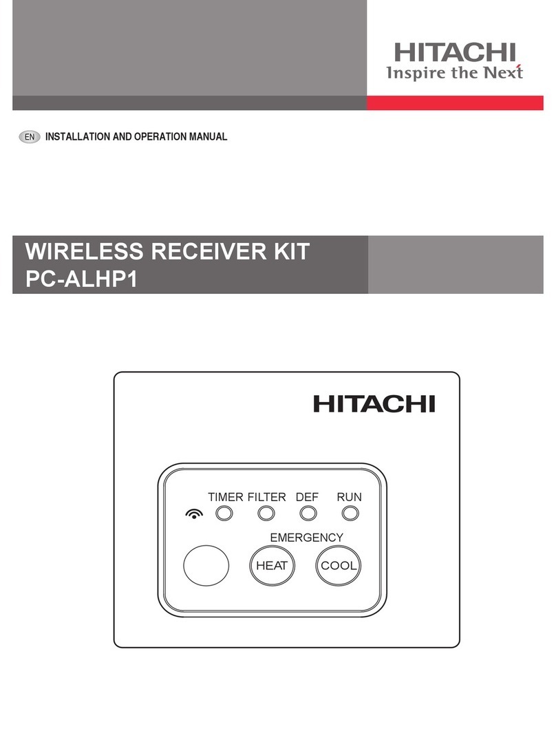
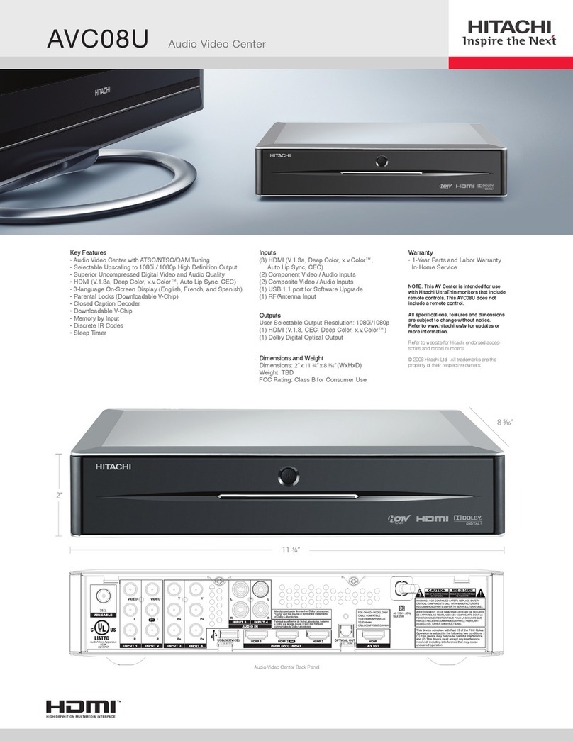
Hitachi PC-ALH User manual

INSTALLATION AND OPERATION MANUAL
MANUAL DE INSTALACIÓN Y FUNCIONAMIENTO
INSTALLATIONS- UND BETRIEBSHANDBUCH
MANUEL D’INSTALLATION ET DE FUNCTIONNEMENT
MANUALE D’INSTALLAZIONE E D’USO
ENGLISH
ESPAÑOL
DEUTSCH
FRANÇAIS
ITALIANO
PORTUGUÊS
DANSK
NEDERLANDS
SVENSKA
MANUAL DE INSTALAÇÄO E DE FUNCIONAMENTO
BRUGER- OG MONTERINGSVEJLEDNING
INSTALLATIE- EN BEDIENINGSHANDLEIDING
HANDBOK FÖR INSTALLATION OCH ANVÄNDING
ΕΓΧΕΙΡΙΔΙΟΕΓΚΑΤΑΣΤΑΣΗΣΚΑΙΛΕΙΤΟΥΡΓΙΑΣ
PC-ALH/PC-ALHD/
PC-ALHZ/PC-ALHC
WIRELESS RECEIVER KIT
Do not perform installation work, without referring to our installation manual.
No realice la instalación de este equipo, sin antes consultar este manual de instalación.
Bei der Installation unbedingt die Hinweise in der Installationsanleitung beachten.
Consulter notre manuel avant de réaliser une quelconque installation.
Realizzare l’installazione, seguendo quanto indicato in questo manuale.
Nao inicie os trabalhos de montagem, sem consultar o nosso manual de montagem.
Udfor ikke installationsarbejder uden forst at donsultere vores vejledning.
Voer geen enkele handeling uit om de apparatuur alvorens deze hadleiding te hebben doorgelezen.
Utför inte nagra installationsarbeten utan att först läsa var installationsmanual
Μην ήσετε στην εγκατάσταση, χωρίς πριν να έχετε συμβουλευθεί αυτo το εγχειρίδιο εγκατάστασης
PMML0174A_r0_11-07.indb 1 22/11/2007 12:49:31

PMML0174A_r0_11-07.indb 2 22/11/2007 12:49:31

Specications in this manual are subject to change without notice in order that HITACHI
may bring the latest innovations to their customers.
Whilst every effort is made to ensure that all specications are correct, printing errors are
beyond Hitachi’s control; Hitachi cannot be held responsible for these errors.
PMML0174A_r0_11-07.indb 3 22/11/2007 12:49:31

ATTENTION:
This product shall not be mixed with general house waste at the end of its life and it shall be retired according to the
appropriated local or national regulations in a environmentally correct way.
Due to the refrigerant, oil and other components contained in Air Conditioner, its dismantling must be done by a
professional installer according to the applicable regulations.
Contact to the corresponding authorities for more information.
ATENCIÓN:
Éste producto no se debe eliminar con la basura doméstica al nal de su vida útil y se debe desechar de manera
respetuosa con el medio ambiente de acuerdo con los reglamentos locales o nacionales aplicables.
Debido al refrigerante, el aceite y otros componentes contenidos en el sistema de aire acondicionado, su desmontaje debe
realizarlo un instalador profesional de acuerdo con la normativa aplicable.
Para obtener más información, póngase en contacto con las autoridades competentes.
ACHTUNG:
Dass Ihr Produkt am Ende seiner Betriebsdauer nicht in den allgemeinen Hausmüll geworfen werden darf, sondern
entsprechend den geltenden örtlichen und nationalen Bestimmungen auf umweltfreundliche Weise entsorgt werden muss.
Aufgrund des Kältemittels, des Öls und anderer in der Klimaanlage enthaltener Komponenten muss die Demontage von
einem Fachmann entsprechend den geltenden Vorschriften durchgeführt werden.
Für weitere Informationen setzen Sie sich bitte mit den entsprechenden Behörden in Verbindung.
ATTENTION:
Ne doit pas être mélangé aux ordures ménagères ordinaires à la n de sa vie utile et qu’il doit être éliminé conformément à
la réglementation locale ou nationale, dans le plus strict respect de l’environnement.
En raison du frigorigène, de l’huile et des autres composants que le climatiseur contient, son démontage doit être réalisé
par un installateur professionnel conformément aux réglementations en vigueur.
ATTENZIONE:
Indicazioni per il corretto smaltimento del prodotto ai sensi della Direttiva Europea 2002/96/EC e Dlgs 25 luglio 2005 n.151
Il simbolo del cassonetto barrato riportato sull’ apparecchiatura indica che il prodotto alla ne della propria vita utile deve
essere raccolto separatamente dagli altri riuti.
L’utente dovrà, pertanto, conferire l’apparecchiatura giunta a ne vita agli idonei centri di raccolta differenziata dei riuti
elettronici ed elettrotecnici, oppure riconsegnarla al rivenditore al momento dell’ acquisto di una nuova apparecchiatura di
tipo equivalente.
L’adeguata raccolta differenziata delle apparecchiature dismesse, per il loro avvio al riciclaggio, al trattamento ed allo
smaltimento ambientalmente compatibile, contribuisce ad evitare possibili effetti negativi sull’ ambiente e sulla salute e
favorisce il riciclo dei materiali di cui è composta l’ apparecchiatura.
Non tentate di smontare il sistema o l’unità da soli poichè ciò potrebbe causare effetti dannosi sulla vostra salute o sull’
ambiente.
Vogliate contattare l’ installatore, il rivenditore, o le autorità locali per ulteriori informazioni.
Lo smaltimento abusivo del prodotto da parte dell’utente può comportare l’applicazione delle sanzioni amministrative di cui
all’articolo 50 e seguenti del D.Lgs. n. 22/1997.
ATENÇÃO:
O seu produto não deve ser misturado com os desperdícios domésticos de carácter geral no nal da sua duração e que
deve ser eliminado de acordo com os regulamentos locais ou nacionais adequados de uma forma correcta para o meio
ambiente.
Devido ao refrigerante, ao óleo e a outros componentes contidos no Ar condicionado, a desmontagem deve ser realizada
por um instalador prossional de acordo com os regulamentos aplicáveis.
Contacte as autoridades correspondentes para obter mais informações.
BEMÆRK:
At produktet ikke må smides ud sammen med almindeligt husholdningsaffald, men skal bortskaffes i overensstemmelse
med de gældende lokale eller nationale regler på en miljømæssig korrekt måde.
Da klimaanlægget indeholder kølemiddel, olie samt andre komponenter, skal afmontering foretages af en fagmand i
overensstemmelse med de gældende bestemmelser.
Kontakt de pågældende myndigheder for at få yderligere oplysninger.
ATTENTIE:
Dit houdt in dat uw product niet wordt gemengd met gewoon huisvuil wanneer u het weg doet en dat het wordt gescheiden
op een milieuvriendelijke manier volgens de geldige plaatselijke en landelijke reguleringen.
Vanwege het koelmiddel, de olie en andere onderdelen in de airconditioner moet het apparaat volgens de geldige
regulering door een professionele installateur uit elkaar gehaald worden.
Neem contact op met de betreffende overheidsdienst voor meer informatie.
OBS!:
Det innebär att produkten inte ska slängas tillsammans med vanligt hushållsavfall utan kasseras på ett miljövänligt sätt i
enlighet med gällande lokal eller nationell lagstiftning.
Luftkonditioneringsaggregatet innehåller kylmedium, olja och andra komponenter, vilket gör att det måste demonteras av
en fackman i enlighet med tillämpliga regelverk.
Ta kontakt med ansvarig myndighet om du vill ha mer information.
ΠΡΟΣΟΧΗ:
Σημαίνει ότι το προϊόν δεν θα πρέπει να αναμιχθεί με τα διάφορα οικιακά απορρίμματα στο τέλος του κύκλου ζωής του και
θα πρέπει να αποσυρθεί σύμφωνα με τους κατάλληλους τοπικούς ή εθνικούς κανονισμούς και με τρόπο φιλικό προς το
περιβάλλον.
Λόγω του ψυκτικού, του λαδιού και άλλων στοιχείων που περιέχονται στο κλιματιστικό, η αποσυναρμολόγησή του πρέπει να
γίνει από επαγγελματία τεχνικό και σύμφωνα με τους ισχύοντες κανονισμούς.
Για περισσότερες λεπτομέρειες, επικοινωνήστε με τις αντίστοιχες αρχές.
PMML0174A_r0_11-07.indb 4 22/11/2007 12:49:32

DANGER – Immediate hazard which WILL result in severe injury or death.
PELIGRO – Riesgos inmediatos que PRODUCIRÁN lesiones personales graves e incluso la muerte.
GEFAHR – Unmittelbare Gefahrenquellen, die zu schweren Verletzungen oder zum Tod führen.
DANGER – Dangers instantanés de blessures corporelles sévères ou de mort.
PERICOLO – Pericolo immediato che PRODURRÀ ferite gravi o la morte.
PERIGO – Problemas imediatos que IRÃO resultar em graves ferimentos pessoais ou morte.
FARE – Overhængende fare, som VIL resultere i alvorlig personskade eller dødsfald.
GEVAAR – Onmiddellijke risico’s die ernstige persoonlijke verwondingen of de dood ten gevolge kunnen hebben.
FARA – Omedelbar risk som medför svår personskada eller död.
KINAYNO – Άµεσος κίνδυνος που ΘΑ έχει ως αποτέλεσµα σοβαρές σωµατικές βλάβες ή θάνατο.
WARNING – Hazards or unsafe practices which COULD result in severe personal injuries or death.
AVISO – Riesgos o prácticas poco seguras que PODRÍAN producir lesiones personales e incluso la muerte.
WARNUNG – Gefährliche oder unsichere Anwendung, die zu schweren Körperverletzungen oder zum Tod führen
kann.
ATTENTION – Utilisation dangereuse ou sans garantie de sécurité qui PEUT provoquer de sévères
blessures personnelles ou la mort.
AVVISO – Pericoli o azioni pericolose che POTREBBERO avere come esito lesioni siche gravi o il decesso.
AVISO – Riesgos o prácticas poco seguras que PUEDEN producir lesiones personales e incluso la muerte
ADVARSEL – Farer eller farlig brug, som KAN resultere i alvorlig personskade eller dødsfald.
WAARSCHUWING – Gevaren of onveilige praktijken die ernstig persoonlijk letsel of de dood tot
gevolg KUNNEN hebben.
VARNING – Risker eller osäkra tillvägagångssätt som KAN leda till svåra personskador eller dödsfall.
ΠΡΟΕΙ∆ΟΠΟΙΗΣΗ – Κίνδυνοι ή επικίνδυνες πρακτικές, οι οποίες ΜΠΟΡΕΙ να έχουν ως αποτέλεσµα σοβαρές
σωµατικές βλάβες ή θάνατο.
CAUTION – Hazards or unsafe practices which COULD result in minor personal injury or product or property
damage.
PRECAUCIÓN – Riesgos o prácticas poco seguras que PODRÍAN provocar lesiones personales de menor
importancia o daños en el producto u otros bienes.
VORSICHT – Gefährliche oder unsichere Anwendung, die geringfügigen Personen-, Produkt- oder Sachschaden
verursachen kann.
PRECAUTION – Utilisation dangereuse ou sans garantie de sécurité qui PEUT provoquer des blessures mineures
ou des dommages au produit ou aux biens.
ATTENZIONE – Pericoli o azioni pericolose che POTREBBERO avere come esito lesioni siche minori o danni al
prodotto o ad altri beni.
CUIDADO – Perigos e procedimentos perigosos que PODERÃO PROVOCAR danos pessoais ligeiros ou danos em
produtos e bens.
FORSIGTIG – Farer eller farlig brug, som KAN resultere i mindre skade på personer, produkt eller ejendom.
LET OP – Gevaren of onveilige praktijken die licht persoonlijk letsel of beschadiging van het product
of eigendommen tot gevolg KUNNEN hebben.
VARSAMHET – Risker eller farliga tillvägagångssätt som KAN leda till mindre personskador eller skador på
produkten eller på egendom.
ΠΡΟΣΟΧΗ – Κίνδυνοι ή επικίνδυνες πρακτικές, οι οποίες ΜΠΟΡΕΙ να έχουν ως αποτέλεσµα την πρόκληση
ελαφρών σωµατικών βλαβών ή καταστροφή περιουσίας.
PMML0174A_r0_11-07.indb 5 22/11/2007 12:49:32

PMML0174A_r0_11-07.indb 6 22/11/2007 12:49:32

7
ENGLISH
SAFETY SUMMARY
1. SAFETY SUMMARY
DANGER
DO NOT pour water into the remote control switch (hereafter called “controller”). This product is equipped with electrical parts.
If poured, it will cause a serious electrical shock.
WARNING
DO NOT perform installation work and electrical wiring connection by yourself. Contact your distributor or dealer of HITACHI
and ask them for installation work and electrical wiring by service person.
CAUTION
DO NOT install the indoor unit, outdoor unit, at such places as:
Where there is oil vapor and the oil is dispersed.
Where the hot springs are near (in a sulfuric environment).
Where generation, owing, staying or leaking of ammable gas is detected
Where the sea is near (in the salty, acid or alkaline environment).
DO NOT install the indoor unit, outdoor unit, within approximately 3 meters from strong electromagnetic wave radiators such as
medical equipment.
In case that there is electric noise at the power source for the indoor unit, provide a noise lter.
Do not turn ON the power source, unless the preparation for test running is completed.
Read this manual carefully before installation work for correct performance.
2. BEFORE INSTALLATION AND OPERATION
The packing contains the following parts. Check the contents and the number of the parts.
NAME Q´TY REMARKS
PC-ALH PC-ALHD PC-ALHZ PC-ALHC
Receiver kit
1
With connection wire
1
1
1
Connecting
cable 1 1 -
Screw
2
For xing receiver kit
4
2For xing clamp.
Clamp 2For xing cable
Cover 1 1 For protection
connecting cable
Band 3 2 1 2 For xing cable
-
-
-
-
PMML0174A_r0_11-07.indb 7 22/11/2007 12:49:34

8
3. INSTALLATION OF WIRELESS RECEIVER KIT
CAUTION
Pay attention to the following installation procedures. If not, it may drop from the panel, resulting in a serious accident.
PC-ALH
1. Install the wireless receiver kit, the indoor unit and the air panel at the same time.
2. In case that the wireless receiver kit is installed after installing the indoor unit, turn off the power source of the indoor unit and
remove the air panel.
3. This receiver kit can be installed at the position 1,2,3 or 4
Air panel
4. Remove the cover of indoor unit electrical control box and connect the cable to the terminal board as shown below.
PCB
Connecting cable
Terminal board
(White)
Indoor unit
Electrical control box
Mark Band “B”
Mark Band “A”
(No polarity in terminals A and B)
5. Draw out the connecting cable from the wiring hole of the indoor unit, and lead the cable over the suspension bracket of the
indoor unit to the installing position of the receiver kit. Bundle the extra cable with a band.
Suspension Bracket
Connecting cable
Wiring hole of
Indoor unit
Connector
6. Install the air panel (option) onto the indoor unit.
INSTALLATION OF WIRELESS RECEIVER KIT
PMML0174A_r0_11-07.indb 8 22/11/2007 12:49:35

9
ENGLISH
7. Attach the receiver kit in the following procedure.
Draw out the connecting cable from the pocket and connect the connecting cable and the wire of the receiver kit. After
connecting the cable, wrap the connector with the cover and x them with a band.
Air panel
Corner pocket
Connecting cable
Receiver kit
Connecting cable
Band
Cover
Band
Hook the band on the rear side of the
receiver kit at the pin of the air panel
as shown bellow.
Pin
Band
Hook L- shaped nail on the rear side of
receiver kit at the square hole of the air panel.
L-Shape hook
Hook (3 locations)
8. Hook other xing nails (3 positions) at square holes of air panel.
NOTE:
When removing the receiver kit after installing the air panel.
a) The corner position of the receiver kit can
be lifted when a coin or a “-” shaped driver
is inserted into the dent part and twisted
downward. With lifted, twist a coin or a
“-” shaped driver at the positions of and
, the whole receiver kit can be lifted.
b) After disconnecting the xing nails (3
positions), slide the receiver kit in the arrow
direction , and remove the receiver kit.
INSTALLATION OF WIRELESS RECEIVER KIT
Dent part
Coin or a “-” Shaped driver
Lifting
PMML0174A_r0_11-07.indb 9 22/11/2007 12:49:37

10
PC-ALHD
1. Install the wireless receiver kit, the indoor unit and the air panel at the same time.
2. In case that the wireless receiver kit is installed after installing the indoor unit, turn off the power source of the indoor unit and
remove the air inlet grille.
3. Fix the wireless receiver kit to the air panel by screws.
(The tightening torque must be 0.8 Nm.)
Air panel (135) Ø7 Boss
Flange Electrical box
for Indoor unit
Cable for wireless
Receiver kit
Screw
(Factory-Supplied)
Cable for
Auto-swing motor
Wireless Receiver kit
4. Lead the cable along the cable for the auto-swing motor and tie them by the band.
Cable for wireless Receiver kit
Band (Factory Supplied) Cable for Auto-Swing Motor
5. Remove the cover of indoor unit electrical control box and connect the cable to the terminals A and B of the terminal board.
(No polarity in terminals A and B).
NOTE:
After connecting the cable, bind up the
remaining cable length portion by band
(Factory-Supplied) and put them in the
electrical control box.
Cable for Receiver kit
Terminal Board
(White)
PCB
Mark Band (B)
Indoor unit electrical box
Mark Band (A)
INSTALLATION OF WIRELESS RECEIVER KIT
PMML0174A_r0_11-07.indb 10 22/11/2007 12:49:39

11
ENGLISH
6. Remove the remote control cover of the air intake grille.
Press the hooks of the remote control cover by hand.
Hook Hook
Air intake grille
Remote
Control Cover Remote
Control Cover
Air intake grille
7. After xing the air panel, attach the air intake grille to the air panel.
Check to ensure that the location of square hole of the air intake grille coincides with location of the wireless receiver kit
of the air panel.
Check to ensure that the cable of the wireless receiver kit is not clamped by the square hole of the air intake grille.
Air intake grille Air panel
Wireless receiver kit
PC-ALHZ
NOTE:
Install the receiver kit onto the wall or ceiling near the indoor unit.
1. Install the wireless receiver kit and indoor unit at the
same time.
2. In case that the wireless receiver kit is installed after
installing the indoor unit, turn off the power source of
the indoor unit.
3. Check to ensure that the distance between the wireless
receiver kit and the indoor unit is less than 5 m.
4. Remove the cover by using minus screw-driver.
−
−
−
INSTALLATION OF WIRELESS RECEIVER KIT
PMML0174A_r0_11-07.indb 11 22/11/2007 12:49:40

12
5. Install the wireless receiver kit onto the wall or ceiling as
follows:
A.In Case of Exposing Cable
Fix the xing bracket of kit by using screw (A)
at 4 locations
Screw (A)
Cut one of the knockout holes (*) at the cover.
Lead the cable through the groove and draw
out the cable from the knockout hole.
Attach the cover. Do not clamp the cable when
attaching the cover.
Cover
Hooking part
Click sound
Fixing bracket
B.In Case of Concealed Cable
Prepare the following box. (Field-Supplied)
JIS Box (JIS C 8336-1991)
a. Switch Box for 1 Controller
(without cover)
b. Small Switch Box for 1
Controller (without cover)
c. Switch Box for 1 Controller
(with cover)
Rigid Metal Conduit (More than Ø20)
Screw (M4) (Field-Supplied)
Insert the cable into the rigid metal conduit.
Cable
Fix the xing bracket of kit by using screw
(Field-Supplied).
This gure shows the case of Switch Box for 1
Controller.
Cable
Screws
(eld-supplied)
Attach the cover same as A.
−
−
INSTALLATION OF WIRELESS RECEIVER KIT
PMML0174A_r0_11-07.indb 12 22/11/2007 12:49:41

13
ENGLISH
6. Remove the cover of indoor unit electrical control box
and connect the cable to the terminals A and B of the
terminal board.
(No polarity in terminals A and B)
NOTE:
After connecting the cable, bind up the remaining cable length portion by band (Factory-Supplied) and put them in the electrical
control box.
PC-ALHC
(Drawing: without suction grill)
1. Install the wireless receiver kit, the indoor unit and
the air panel at the same time.
2. In case that the wireless receiver kit is installed after
installing the indoor unit, turn off the power source of
the indoor unit and remove the air panel.
3. This receiver kit can be installed only at one position.
The installation position
Wiring hole
Electrical control box
Pipe connecting side
4. Remove the cover of indoor unit electrical control box
and connect the cable to the terminal board (white)
as shown beside.
(No polarity in terminals A and B)
Terminal board (white)
Indoor unit electrical control box
PCB
Mark band “A” Mark band “B”
Connecting cable
INSTALLATION OF WIRELESS RECEIVER KIT
PMML0174A_r0_11-07.indb 13 22/11/2007 12:49:42

14
5. Draw out the connecting cable from the wiring hole of the indoor unit, and lead the cable to the installing position of
the receiver kit.
6. Install the air panel (option) onto the indoor unit.
7. Attach the receiver kit in the following procedure.
Draw out the connecting cable from the pocket and connect the connecting cable and the wire of the receiver kit.
After connecting the cable, wrap the connector with the cover and x them with a band.
Air panel
Corner pocket
Connecting cable
Receiver kit
Band
Cover
Band
Connecting
cable
Hook the band on the rear side of the receiver kit at
the pin of the air panel as shown bellow.
Hook L- shaped nail on the rear side of receiver kit
at the square hole of the air panel, and x it with the
screw.
Pin
Band
L-shaped nail
Screw
Nail (2 position)
8. Attach other pocket cover (3 positions) to the air panel.
NOTE:
When removing the receiver kit after installing the air
panel:
a) Remove the screws of (4 positions) from
the front side of the air panel.
b) Move the Receiver kit with hands in the
arrow direction and remove the nails (2
positions) of pocket cover for corner, and
slide the receiver kit in the arrow direction .
INSTALLATION OF WIRELESS RECEIVER KIT
PMML0174A_r0_11-07.indb 14 22/11/2007 12:49:43

15
ENGLISH
4. OPTIONAL FUNCTIONS
PC-ALH / PC-ALHC
Switch “COOL” Switch “HEAT”
Dip Switch
(SW3: Factory Supplied)
Rear side of Indoor unit
Cover
Remove the screw
Optional Setting for Dip Switch (SW3)
Operation function DIP Switch Setting (SW3)
Setting of Sub Receiver kit
1 2 3 4 5 6
Identifying of Indoor units
1 2 3 4 5 6
NOTE:
Contact your distributor or dealer of Hitachi for details.
PC-ALHD
Switch “COOL”
Switch “HEAT”
Dip Switch
(SW3: Factory Setting)
Hole for cable
Cover Printed circuit board Case
Remove two
screws and open
the case
PC-ALHZ
Switch “COOL”
Switch “HEAT”
Hole for cable
Cover Printed circuit
board Case
1. Remove the base.
2. Remove two screws and open
the case.
Base
Dip switch
(SW3: Factory setting)
OPTIONAL FUNCTIONS
PMML0174A_r0_11-07.indb 15 22/11/2007 12:49:45

16
5. OTHERS
1. In case of simultaneous operation of plural (up to 16) units by the wireless remote control switch, apply the receiver kit only to
the unit to be operated, and apply the standard units (without receiver kit) to the others.
In case of applying plural receiver kit, up to 2 receiver kits can be used.
2. Proceed the “TEST RUN” mode by using “Operation & Installation Manual” for the wireless remote control switch (PC-LH3A).
Turn OFF all power sources before setting the dip switches.
3. Emergency Operation Setting (refer to the gure of the item 4 “Optional Functions”)
In case that PC-LH3A is unusable by batteries shortage, etc., perform emergency operation as follows.
(a). Switch “COOL”: Press “COOL” so that the cooling operation is started.
Press “COOL” again so that the cooling operation is stopped.
(b). Switch “HEAT”: Press “HEAT” so that the heating operation is started.
Press “HEAT” again so that the heating operation is stopped.
NOTE:
During the emergency operation, the LED (yellow) blinks
(0.5 second ON / 0.5 second OFF).
4. Alarm Code Indication
In case that some trouble occures because of activation of safety device, etc., “RUN” (red lamp)
blinks (0.5 second ON / 0.5 second OFF).
Refer to the Installation Manual for outdoor unit about Alarm Code List.
Alarm Code indicates the blinking times of “DEF” (green lamp) and “FILER” (yellow lamp) as shown bellow.
“DEF” (green lamp): the blinking is shown at the 2 digit of Alarm Code
“FILTER” (yellow lamp): the blinking is shown at the 1 digit of Alarm Code
(Alphabet Code: A=10 times, B=11 times, C=12 times, ...)
Example:
Alarm
“FILTER” (yelow lamp)
“DEF (green lamp)
“DEF” blinks 3 times 0.5 times (0.5 second ON / 0.5 second OFF)
“FILTER” (yelow lamp) blinks 5 times (0.5 second ON / 0.5 second OFF)
“RUN” (red lamp) (1 second ON / 1 second OFF) indicates abnormal transmitting between
Indoor Units and Outdoor Unit
-
−
−
−
-
OTHERS
PMML0174A_r0_11-07.indb 16 22/11/2007 12:49:45

17
ENGLISH
5. Horizontal distance limit of remote controller:
Ceiling
Height of indoor unit
Wireless
Remote Controller
Horizontal
distance
Floor
Indoor unit (Air panel)
Receiver kit
Horizontal distance limit of remote control (in the case that height of remote controller from oor is 1 m):
RCIM
Height of indoor unit (m) 2.7 3.0 3.5 4.0
Horizontal distance (m) 2.9 3.5 4.0 4.5
RCI
Height of indoor unit (m) 2.7 3.0 3.5 4.0 4.5 5.0
Horizontal distance (m) 2.9 3.5 4.0 4.5 4.5 4.5
RCD/RPI
Height of indoor unit (m) 2.5 3.0 3.5 3.8
Horizontal distance (m) 2.5 3.5 4.0 4.0
6. Checking of command reception. Lamp (yellow) of receiver part in receiver kit blinks when receiver kit receive commands from
wireless remote controller. If lamp does not blink, commands are not sent correctly. Send commands again.
NOTE:
Beep as well as lamp blink when commands are received correctly.
The beep may not be heard due to the ambient noise.
7. Other Receiver Kit indications:
(For gas heat pump air conditioner only)
When using a gas heat pump air conditioner, “FILTER” LED (yellow) and “TIMER” LED (green) may blink at the same time. This
does not mean abnormality, but indicates the periodical checking of the engine is coming soon or has already passed.
“FILTER” (yellow) and “TIMER” (green) lamps blink slowly (every two seconds). Indicates that the periodical checking of the
engine is coming soon.
“FILTER” (yellow) and “TIMER” (green) lamps blink rapidly (every 0.5 seconds). Indicates that the timing of periodical checking
of the engine has already passed.
Ask for periodical checking when these indications appear.
8. Wall mount (RPK) Dip Switch setting:
a) The factory setting of SW1 is “Wireless”. To use with a receiver kit, slide SW1 to change to “Wired”.
b) Dip switch shall be set when both Indoor and Outdoor unit power is OFF. Setting congured with Indoor and/or Outdoor unit
power ON will be invalid.
9. The temperature setting is available from 17ºC to 30ºC by using a wireless remote control switch. The temperature range is
different depending on the indoor unit model. For the unit with the temperature setting range is 19ºC to 30ºC, 17ºC and 18ºC can
not be set by the wireless remote switch.
−
−
−
OTHERS
PMML0174A_r0_11-07.indb 17 22/11/2007 12:49:46


67
PORTUGUÊS
RESUMO DA SEGURANÇA
1. RESUMO DA SEGURANÇA
PERIGO
NÃO molhe o controlo remoto (daqui para a frente denominado “controlador”). Este produto está equipado com peças
eléctricas.
Se as mesmas forem molhadas, ocorrerá um choque eléctrico grave.
ATENÇÃO
NÃO faça você mesmo qualquer trabalho de instalação nem de ligações eléctricas. Entre em contacto com o seu distribuidor
ou revendedor da HITACHI e solicite um técnico para efectuar os trabalhos de instalação e as ligações eléctricas.
CUIDADO
NÃO instale a unidade interior nem a unidade exterior em lugares como:
Onde exista vapor de óleo ou óleo disperso.
Num ambiente sulfúrico.
Perto de gases ou condutas de gases inamáveis
Perto do mar (num ambiente salino, ácido ou alcalino).
NÃO instale as unidade interior nem a unidade exterior a menos de, aproximadamente, 3 metros de fontes fortes de radiação
electromagnética, tais como equipamentos médicos.
Se existir ruído eléctrico na fonte de alimentação da unidade interior, instale um ltro de ruído.
NÃO ligue a fonte de alimentação antes da preparação para a prova de funcionamento estar concluída.
Leia atentamente este manual antes de efectuar os trabalhos de instalação, de modo a obter um desempenho adequado.
2. ANTES DA INSTALAÇÃO E DA ENTRADA EM FUNCIONAMENTO
A embalagem contém as peças seguintes. Verique o conteúdo e o número das peças.
NOME QTD. OBSERVAÇÕES
PC-ALH PC-ALHD PC-ALHZ PC-ALHC
Receiver
kit (kit
receptor)
1
Com cabo de ligação
1
1
1
Cabo de
ligação 1 1 -
Parafuso
2Para xar o kit
receptor
4
2Para xação de
abraçadeira.
Abraçadeira 2Para xação de cabo
Tampa 1 1 Para protecção de
cabo de ligação
Abraçadeira
exível 3 2 1 2 Para xação de cabo
-
-
-
-
PMML0174A_r0_11-07.indb 67 22/11/2007 12:50:42

68
3. INSTALAÇÃO DE KIT RECEPTOR SEM FIOS
CUIDADO
Preste atenção aos seguintes procedimentos de instalação. No caso contrário, a unidade pode cair, o que provocaria danos
consideráveis.
PC-ALH
1. Instale o kit receptor sem os, a unidade interior e o painel de ar ao mesmo tempo.
2. Se o kit receptor sem os for instalado depois da unidade interior, desligue a fonte de alimentação da unidade interior e retire o
painel de ar.
3. Este kit receptor pode ser instalado na posição 1,2,3 ou 4
Painel de ar
4. Retire a tampa da caixa de controlo eléctrico da unidade interior e ligue o cabo à placa de terminais, como se mostra abaixo.
PCB
Cabo de ligação
Placa de terminais
(Branco)
Unidade interior
Caixa de controlo eléctrico
Abraçadeira “B”
Abraçadeira “A”
(Os terminais A e B não têm polaridade)
5. Puxe o cabo de ligação pelo furo de ligações eléctricas da unidade interior e passe o cabo por cima do suporte de suspensão
da unidade interior até à posição de instalação do kit receptor. Junte o cabo excedente com uma abraçadeira.
Suporte de suspensão
Cabo de ligação
Furo de ligações
eléctricas de
unidade interior
Conector
6. Instale o painel de ar (opcional) na unidade interior.
INSTALAÇÃO DE KIT RECEPTOR SEM FIOS
PMML0174A_r0_11-07.indb 68 22/11/2007 12:50:44
This manual suits for next models
3
Table of contents
Languages:
Other Hitachi Receiver manuals

Hitachi
Hitachi WorldSpace KH-WS1 User manual

Hitachi
Hitachi PC-ALHZF User manual

Hitachi
Hitachi PC-ALH5Q User manual

Hitachi
Hitachi PC-ALHP1 User manual

Hitachi
Hitachi AllPlay Adaptor User manual

Hitachi
Hitachi ACV01U - LCD Direct View TV User manual

Hitachi
Hitachi AVC08U - Digital TV Tuner User manual

Hitachi
Hitachi HTA-DD1E User manual

Hitachi
Hitachi HTADD3WAU User manual

Hitachi
Hitachi HTD-K185UK User manual