Hitachi ATW-RTU-01 User manual

INSTALLATION AND OPERATION MANUAL
MANUAL DE INSTALACIÓN Y FUNCIONAMIENTO
INSTALLATIONS- UND BETRIEBSHANDBUCH
MANUEL D’INSTALLATION
MANUALE D’INSTALLAZIONE E D’USO
MANUAL DE INSTALAÇÃO E DE FUNCIONAMENTO
BRUGER- OG MONTERINGSVEJLEDNING
INSTALLATIE- EN BEDIENINGSHANDLEIDING
INSTALLATIONS- OCH ANVÄNDARHANDBOK
ΕΓΧΕΙΡΙΔΙΟ ΕΓΚΑΤΑΣΤΑΣΗΣ ΚΑΙ ΛΕΙΤΟΥΡΓΙΑΣ
Wireless Programmable Room thermostat (ATW-RTU-01)
Termostato de ambiente inalámbrico y programable
(ATW-RTU-01)
Kabelloser, programmierbarer Raumthermostat
(ATW-RTU-01)
Thermostat d’ambiance sans fil programmable (ATW-RTU-01)
Termostato ambientale senza fili programmabile
(ATW-RTU-01)
Termostato programável sem fios de espaço interior (ATW-RTU-01)
Trådløs programmerbar rumtermostat (ATW-RTU-01)
Draadloze programmeerbare kamerthermostaat (ATW-RTU-01)
Programmerbar trådlös rumstermostat (ATW-RTU-01)
Ασύρματος προγραμματιζόμενος θερμοστάτης δωματίου (ATW-RTU-01)
Do not perform installation work without referring to our installation manual.
No realice trabajos de instalación sin consultar el manual de instalación.
Führen Sie die Installationsarbeiten gemäß dem Installationshandbuch durch.
Consulter notre manuel avant de réaliser une quelconque installation.
Gli interventi d’installazione devono essere eseguiti attenendosi alle istruzioni contenute in questo manuale.
Não execute trabalhos de instalação sem antes consultar o nosso manual de instalação.
Udfør ikke monteringsarbejde uden først at læse monteringsvejledningen.
Begin niet met de installatie voordat u de installatiehandleiding hebt doorgelezen.
Utför inte något installationsarbete utan att först läsa installationshandboken.
Μην εκτελείτε εργασίες εγκατάστασης χωρίς να ανατρέξετε στο εγχειρίδιο εγκατάστασης.
DEUTSCH ENGLISHESPAÑOLFRANÇAISITALIANOPORTUGUÊS
DANSK
SVENSKA NEDERLANDS DEUTSCH ENGLISHESPAÑOLFRANÇAISITALIANOPORTUGUÊS
DANSK
SVENSKA
Ελληνικα NEDERLANDS

2
Description
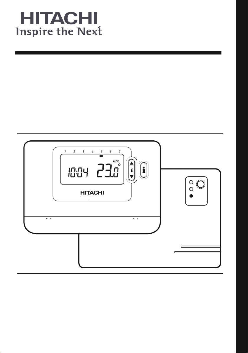
The Room Unit communicates with the RF Receiver
on an 868MHz Radio Frequency (RF) band to control the
AquaFREEsystem. Neither product will communicate
with other RF products that use different frequencies or
communication protocols.
Note: The RF link between the Room Unit and RF Receiver in
system packs is pre-configured at the factory and therefore these
components SHOULD be installed at the same site. This makes the
installation process fast and easy, but if products from individual
system packs are separated, or mixed with other pre-configured
system packs during installations please refer to section 4. Binding
/ Rebinding Procedure to bind the desired units together and
allow them to communicate with each other.
Table of Contents
Section Page
1. Installation Information .........................................................................................................................3
2. Installing the Programmable thermostat.............................................................................................4
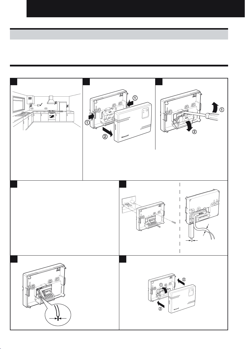
2.1 Installing the RF Receiver..................................................................................................................4
2.2 Installing the Room Unit.....................................................................................................................5
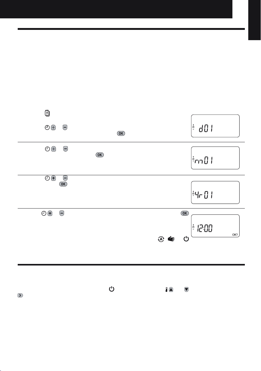
2.2.1 Power Up....................................................................................................................................5
2.2.2 RF Communication Check..........................................................................................................5
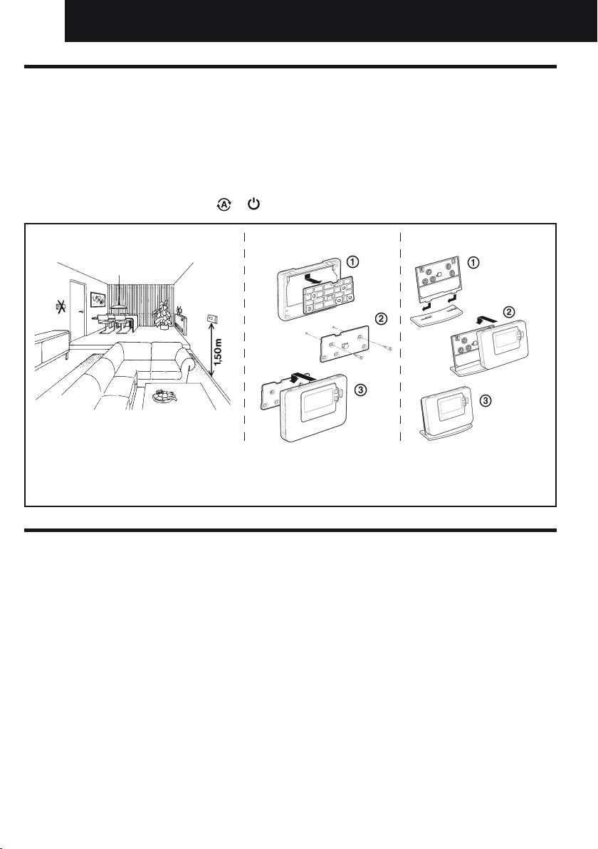
2.2.3 Locating the Room Unit..............................................................................................................6
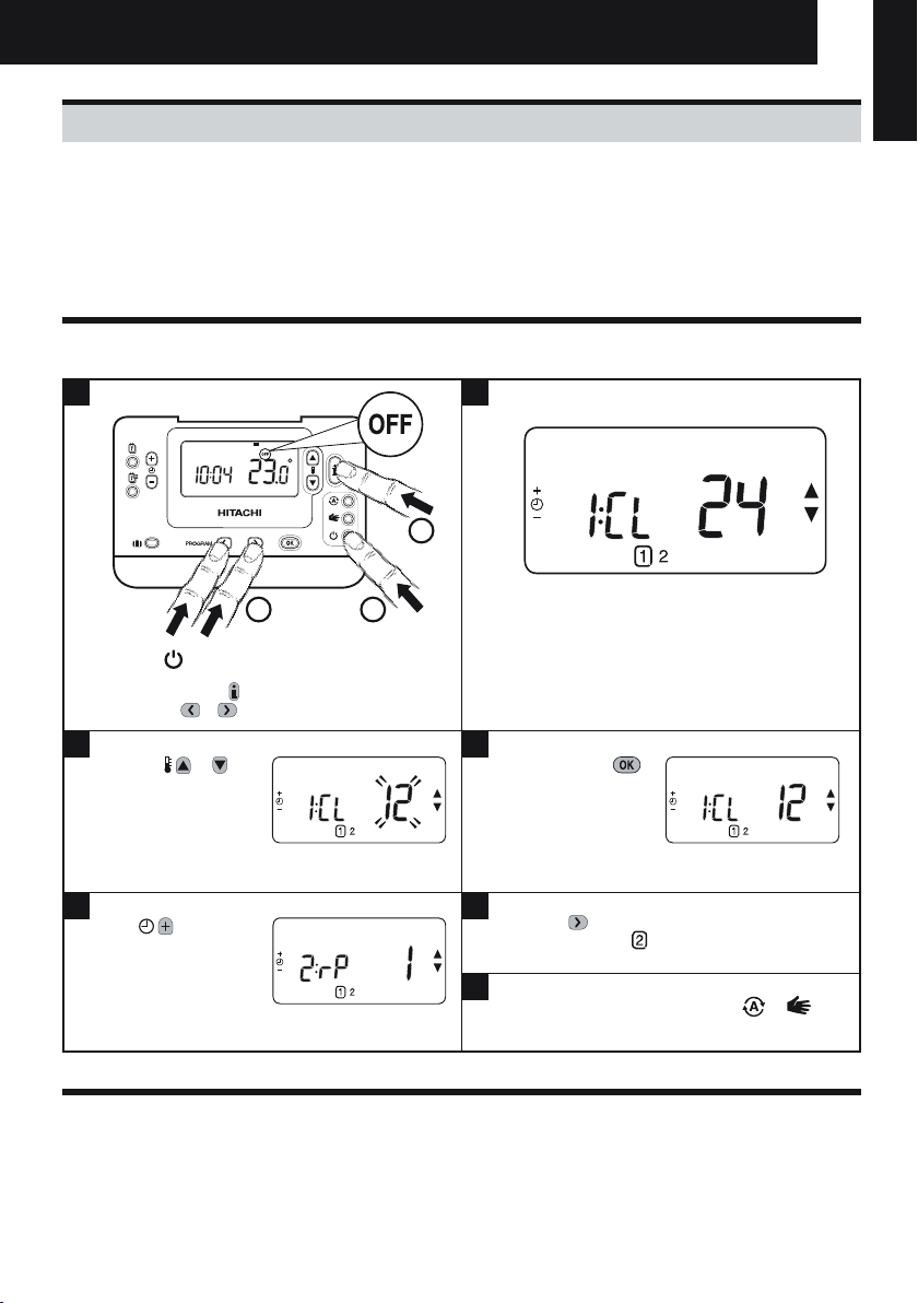
3. Installer Mode.........................................................................................................................................7
3.1 Entering Installer Mode......................................................................................................................7
3.2 Fail-Safe Mode Setup ........................................................................................................................7
3.3
Using the Room Unit for Specific Applications ..................................................................................8
3.4
Using the Special Features of the Room Unit ....................................................................................8
3.5 Installer Parameters Table .................................................................................................................9
3.5.1 Category 1 - Room Unit Settings................................................................................................9
3.5.2 Category 2 - System Settings...................................................................................................10
4. Binding / Rebinding Procedure ..........................................................................................................11
5. Trouble Shooting .................................................................................................................................12
5.1 Trouble Shooting Guide ...................................................................................................................12
Installation and Operation Manual

3
1. Installation Information
As these products communicate using RF technology special care must be taken during installation.
The location of the RF components as well as the building structure may influence performance of the
RF system. To assure system reliability, please review and apply the information given below.
Within a typical residential building the two products should communicate reliably within a 30m range.
It is important to take into consideration that walls and ceilings will reduce the RF signal. The strength
of the RF signal reaching the RF Receiver depends on the number of walls and ceilings separating it
from the Room Unit, as well as the building construction - the diagram below illustrates an example of
typical signal strength reduction. Walls and ceilings reinforced with steel or plasterboard walls lined with
metal foil reduce the RF signal significantly more.
Once a position is selected for the Room Unit this can be checked using the RF Communication Test
mode as described in section 2.2.3 Locating the Room Unit on page 6. If the position is unsuitable the
RF Receiver will not respond and an alternative position for the Room Unit must be selected.
Typical example of Building Fabric Signal losses
Wall Wall Wall
Ceiling
Max. Signal Length 30 metres
= Signal Strength
Installation and Operation Manual
ENGLISH

4
2. Installing the Programmable thermostat
Please follow the illustrations and information below in sequence to install the RF Receiver and Room
Unit correctly. To enable special features and see what other system options are available refer to section
3. Installer Mode on page 7.
2.1 Installing the RF Receiver
Installation and Operation Manual
1
The receiver box is a RF device.
For the best performance install
in an open space. Leave at least
30cm distance from any metal
objects including wall boxes and
boiler housing.
Do not mount on metal wall
boxes.
NOTE: The receiver box contains no user serviceable parts. It should
be opened and installed by qualified installer only.
WARNING: Electrostatic sensitive device! Do not touch the circuit
board.
NOTE: For receiver and unit connection refer to
unit installation manual.
NOTE: All wiring must be in accordance with
IEE regulations.
CAUTION: Observe ambient temperature and
current limits (see the RF Receiver wiring label)
max. 2.5mm²
2 3
7
4
> 7mm Ø
< 7mm Ø
5a. b.
6

5
2.2.2 RF Communication Check (Test Mode)
To check the RF communication, hold the Room Unit about 2-3 metres from the installed RF Receiver.
Set the Room Unit to off by pressing the button. then press the and buttons together with the
button for 3 seconds. The unit will display ‘tESt’ and it will send test signals to the RF Receiver. If
the test signals are received the LED on the RF Receiver, will flash between 1 and 5 times. Flashing
the green LED on every 5 seconds (relay output will remain off) for a maximum of 10 minutes. When the
green LED flashes on every 5 seconds proceed to the next step.
NOTE: If the green LED is not switched at specified intervals, the red LED is flashing or if you are installing a
replacement RF Receiver or Room Thermostat, follow the procedures described in section 4 Binding / Rebinding
Procedure on page 11.
2.2 Installing the Room Unit
2.2.1 Power Up
Installing the Batteries:
a. Lift up the front cover of the Room Unit to reveal the battery cover and product controls.
b. Remove the battery cover by pressing down and sliding out.
c. Insert the 2 x AA LR6 Alkaline Batteries supplied with the Room Unit, ensuring the correct orientation.
d. After a short pause the Room Unit will display information on the screen and is now ready for use.
e. Replace the battery cover by sliding it firmly back into the front of the Room Unit.
Setting the Date and Time:
a. Press the button to begin setting the date. When you set the date for the
first time after the batteries are inserted, the display will show:
Press the or buttons to set the current day of the month (e.g. d 01 =
1st day of the month) then press the green button to confirm.
b. Press the or buttons to set the current month of the year (e.g. m 01
= January) then press the green button to confirm.
c. Press the or buttons to set the current year (e.g. yr 07 = 2007) then
press the green button to confirm.
The date is now stored and the Day Indicator will be displayed under the
current day of the week (e.g. 1 = Monday, 2 = Tuesday, etc.)
d. Use the or buttons to set the correct time then press the green
button to confirm. Each press of the buttons will change the time by one
minute and holding them down will change the time slowly at first and get
progressively quicker.
Note: If this mode is entered accidentally then press the , or
buttons to exit.
AM
ENGLISH
Installation and Operation Manual
ENGLISH

6
2.2.3 Locating the Room Unit
While still in the Test Mode, as described in section 2.2.2, the Room Unit should be located taking the
following into consideration and reviewing the illustrations below:
1.
Find a suitable location where the signal transmission is reliable. Reliable transmission is indicated when
the RF Receiver is flashing the green LED every 5 seconds. NOTE : The RF Receiver will be off.
2. Install the Room Unit EITHER on the wall using the wall bracket OR attach the optional table stand as
shown in below.
3. Exit the Test Mode by pressing the or button.
Wall bracket Table stand
•TheRoom Unit should be installed in an open space for best performance as it is a radio frequency device.
•
Leave at least 30cm distance from any metal objects including wall boxes and at least 1 metre from any other
electrical equipment eg. radio, TV, PC etc.
•Donotmountontometalwallboxes.•ItisrecommendedthattheRF Receiver is fully installed.
Installation and Operation Manual

7
3.1 Entering Installer Mode
3.2 Fail-Safe Mode Setup
The fail-safe mode defines the RF Receiver box output relay status if the RF communication is lost (e.g.
when the Room Unit stops communicating due to discharged batteries).
The factory setting keeps the relay permanently off when the communication is lost.
3. Installer Mode
Installer Mode is used to alter the system settings for specific applications, to use the special features
of the Room Unit in a different way or to alter the factory preset parameters. Parameters are divided
into two groups:
- Category 1 parameters – Room Unit Setup
- Category 2 parameters – System Setup.
These are all listed in section 3.5 Installer Parameters Table.
Press the button.
Press and hold the button and the
PROGRAM & buttons together.
Press the or to
change factory setting.
The display will flash
indicating that a change
has been made.
Press the green
button to confirm the
change.
The display will stop
flashing.
Press the button to go to Installer parameter
group category 2 ( ) (from Parameter n.4 to n.14).
To exit the installer mode press the or
buttons.
Press button
to go to the next
parameter.
The unit will display the first parameter of installer
parameter group category 1 (from Parameter n.1
to n.19) as shown
1 2
3 4
5 6
7
1..6
MANAUTO
1234567
1
2
2
Installation and Operation Manual
ENGLISH

8
3.3 Using the Room Unit for Specic Applications
The Room Unit is a versatile controller that can be used to control many different applications. Some of
the system parameters within the Room Unit menu will not apply. Please also note other changes to the
setting of the optimisation and proportional band settings as shown in tables 3.5.1 and 3.5.2.
NOTE: In order for the Room Unit to send the heating demand signal to the RF Receiver, it is essential
that the Category 2 parameter 8:Su is set to the correct value (see Installer Parameters Table, 3.5.2
Category 2 – System Settings). Failure to do this will mean that the heating system will not respond to
changes in the setpoint on the Room Unit. Under these circumstances the system will operate with no
input from the Room Unit and may not therefore provide adequate temperature control.
3.4 Using the Special Features of the Room Unit
Special Feature: Description: Enable/Disable
Heating or Cooling
Operation
This product can be used for heating or cooling
applications. If you select cooling mode the control
algorithm and factory default program will be modified. You
can independently modify the heating and cooling profile.
To enable: Set parameter 4:HC
(category 2) to 1.
Summer/Winter
Auto time change
This feature moves time automatically on the last Sunday
of March and the last Sunday of October. The feature is
factory enabled.
To enable: Set parameter 3:tC
(category 1) to 1.
Temperature Offset If the Room Unit is located in a particularly hot/cold
location for reliable signal transmission reasons then the
measured/displayed temperature can be adjusted by +/-
3°C. This is useful if the homeowner wants the reading to
match another appliance temperature display.
Set parameter 12:tO (category
1) to the required offset value.
Upper/Lower
Temperature Limit
The normal upper temperature limit of 35°C can be
reduced to 21°C to save the homeowner energy. The
normal lower limit of 5°C can be increased up to 21°C to
protect inhabitants from cold.
Set parameter 6:uL (category 1)
to the desired upper limit.
Set parameter 7:LL (category 1)
to the desired lower limit.
Installation and Operation Manual

9
3.5 Installer Parameters Table
3.5.1 Category 1 - Room Unit Settings
Note
Remember to always press the green button to confirm that you want to store your new Installer
Set-Up setting. To exit the Installer Mode press the or button.
Parameter Parameter
No. Factory Default Setting Optional Setting
Category 1 Parameters – Room Unit Settings
Display Description Display Description
AM-PM / 24hr
Display 1:CL 24 24 hr clock display
format 12 12 hr – AM/PM clock display
format
Reset Time/ Temp
Program 2:rP 1 Time / Temp profile
set to factory default
Changes to 0 when
one of the time/temp
profiles are changed
0 Time / Temperature are as
programmed
To restore the factory profile set
to 1
Auto Summer/
Winter Time
Change
3:tC 1 Auto Summer/
Winter Time Change
Enabled
0 Auto Summer/Winter Time Change
Disabled
LCD Backlighting 5:bL 1 Backlighting Enable 0 Backlighting Disabled
Upper Temp Limit 6:uL 35 35°C Upper Temp.
Limit 21 to
34 21°C to 34°C adjustment in 1°C
steps
Lower Temp Limit 7:LL 5 5°C Lower Temp.
Limit 5 to 21 6°C to 21°C adjustment in 1°C
steps
Optimisation 8:OP 0 Optimisation
Disabled 1 Optimisation Enabled
Temperature
Offset 12:tO 0 No temperature
offset -3 to
+3 -3°C to +3°C adjustment in 0.1°C
steps
Proportional Band
Width 13:Pb 1.5 Proportional band of
1.5 degrees 1.6 to
3.0 1.6°C to 3.0°C adjustment in 0.1°C
steps
Reset Parameters
to Factory
Defaults
19:FS 1 All settings at factory
defaults
Changes to 0 when
one of the parameter
is changed
0 Settings are as modified above
To restore the factory profile set
to 1
Installation and Operation Manual
ENGLISH

10
3.5.2 Category 2 - System Settings
NOTE: To ensure correct heat pump system operation, parameter 8:Su must be set correctly. See note in
section 3.3 Using the Room Unit for Specic Applications.
Note
Remember to always press the green button to confirm that you want to store your new Installer Set-Up
setting. To exit the Installer Mode press the or button.
Parameter Parameter
No. Factory Default Setting Optional Setting
Category 2 Parameters – System Settings (press the button to access this category)
Heat/Cool selection
enable / disable 4:HC 0 Disabled 1 Enabled
Room Temperature
Sensor Use 8:Su 0 Programmer and room
compensation unit
(ON/OFF receiver)
1 For Extension controller
Maximum Flow
Setpoint (extension
systems only)
11:uF 55 55°C Maximum Flow
Temp. 0 to 99 0°C to 99°C adjustment in 1°C steps
Minimum Flow
Setpoint (extension
systems only)
12:LF 15 15°C Minimum Flow
Temp. 0 to 50 0°C to 50°C adjustment in 1°C steps
Mixing Value Run
Time (extension
systems only)
13:Ar 150 150 seconds 0 to
240 0 to 240 sec. adjustment in 1sec
steps
Pump Overrun Run
Time (extension
systems only)
14:Pr 15 15 minutes 0 to 99 0 to 99 mins adjustment in 1min steps
Installation and Operation Manual

11
4. Binding / Rebinding Procedure
The binding operation described below is required if:
• Anyofthesystemcomponents(Room Unit or RF Receiver) are replaced.
• The RF Receiver has incorrect or no binding data stored (e.g. when pre-bound system pack
components have been mismatched).
NOTE: During the binding procedure keep approximately 1m distance between the Room Unit and the RF
Receiver.
To bind/rebind:
1. Hold button on RF Receiver for 15 seconds. LED will flash red 0.1 sec ON, and 0.9 sec OFF
2. Hold button on RF Receiver for 5 seconds. LED will flash red for 0.5 sec ON, and 0.5 sec OFF.
3. Press the button on the Room Unit
4. Hold , and buttons for 2 seconds. Display will show “InSt CO”. The boiler and RF signal
icons will be displayed.
5. Press the green button.
6. When Red LED on the RF Receiver goes off, the devices are bound.
7. If binding is unsuccessful, then the LED will stay on. In this case, move the Room Unit and repeat
the procedure from the beginning.
8. The LED on the RF Receiver will flash green every 10 seconds to indicate that the device is live.
9. Now go to Section 2. Installing the Programmable thermostat to setup the system.
Installation and Operation Manual
ENGLISH

12
5. Trouble Shooting
5.1 Trouble Shooting Guide
Symptom (Fault Message) Possible Cause Remedy
The room thermostat
displays the symbol but
the receiver box relay does
not switch on.
This is normal operation. The receiver
box cycles the relay on and off for times
proportional to the demand signal (0-100%)
from the room thermostat. The symbol
only indicates that the demand value is
greater than 0%.
Using the button change the
temperature setpoint by a few degrees. The
receiver box should switch the relay on after
a few seconds delay.
The receiver box does not
react to setpoint changes
on the room thermostat.
The room thermostat and receiver box are
not bound.
Reset the receiver box by pressing
and holding the push button for 15
seconds. Then follow the binding /
rebinding procedure as described
in section 4) Binding / Rebinding
procedure.
After the binding procedure
the red LED is on and the
green one is flashing once
every 3 sec on the receiver
box.
Incorrect or incomplete binding procedure.
Incorrect position of the room thermostat
during binding.
Repeat the binding procedure.
Repeat the binding procedure keeping
approx. 1 m distance between the
receiver
box and the room thermostat.
The red LED is on the
receiver box
(Communication loss)
The receiver box receives no RF messages
from the room thermostat:
RF signal is blocked due to wrong location
of the room thermostat.
Room thermostat batteries are exhausted.
Re-locate the room thermostat following
instructions in section 2) Installing the
programmable thermostat.
Replace batteries in the room
thermostat.
Installation and Operation Manual

13
Descripción
La unidad de la habitación se comunica con el receptor
RF en una banda de radiofrecuencia (RF) de 868 MHz
para controlar el sistema AquaFree. Ningún producto se
comunicará con otros productos RF que utilicen distintas
frecuencias o protocolos de comunicación.
Nota:ElenlaceRFentrelaunidaddelahabitaciónyelreceptor
RF de los paquetes del sistema viene preconfigurado de
fábrica, por tanto, estos componentes DEBEN instalarse en
el mismo lugar. Esto hace que el proceso de instalación sea
rápido y sencillo, pero si los productos de determinados
paquetes del sistema están separados o mezclados con
otros paquetes del sistema preconfigurados durante
instalaciones, consulte el apartado Procedimiento de unión/
reunión para unir las unidades deseadas y hacer posible la
comunicación entre ellas.
Índice
Apartado Página
1. Instalación de las unidades ................................................................................................................14
2. Instalación del termostato programable............................................................................................15
2.1 Instalación del receptor RF..............................................................................................................15
2.2 Instalación de la unidad de la habitación........................................................................................16
2.2.1 Encendido ................................................................................................................................16
2.2.2 Comprobación de la comunicación RF....................................................................................16
2.2.3 Ubicación de la unidad de la habitación .................................................................................17
3. Modo de instalador..............................................................................................................................18
3.1 Entrada en modo de instalador .......................................................................................................18
3.2 Configuración del modo a prueba de fallos ....................................................................................18
3.3
Uso de la unidad de la habitación para aplicaciones específicas..................................................19
3.4
Uso de las características especiales de la unidad de la habitación.............................................19
3.5 Tabla de parámetros del instalador .................................................................................................20
3.5.1 Categoría 1: ajustes de la unidad de la habitación .................................................................20
3.5.2 Categoría 2: ajustes del sistema..............................................................................................21
4. Procedimiento de unión/reunión........................................................................................................22
5. Resolución de problemas ...................................................................................................................23
5.1 Resolución de problemas................................................................................................................23
Manual de instalación y funcionamiento
ESPAÑOL

14
1. Instalación de las unidades
Como estos productos se comunican utilizando tecnología RF debe tenerse mucho cuidado durante
la instalación. La ubicación de sus componentes, así como la estructura del edificio, puede influir en
el rendimiento del sistema RF. Para garantizar la fiabilidad del sistema, revise y aplique la información
que se ofrece a continuación.
Dentro de un edificio residencial típico, los dos productos deben comunicarse de forma fiable en un
campo de 30 m. Es importante tener en cuenta que las paredes y los techos reducirán la señal de RF.
La intensidad de las señales que llegan al receptor RF depende del número de paredes y techos que
lo separen desde la unidad de la habitación, así como de la construcción del edificio. En el diagrama
siguiente se muestra un ejemplo típico de reducción de la intensidad de la señal. Las paredes y techos
reforzados con acero o las paredes de pladur con perfiles metálicos reducen considerablemente más
la señal RF.
Una vez que se selecciona un lugar para la unidad de la habitación, se puede hacer una comprobación
de dicho lugar mediante el modo de prueba de comunicación RF según se describe en el apartado
2.2.3 Ubicación de la unidad de la habitación en la página 6. Si la posición no es adecuada, el receptor
RF no responderá y deberá elegir otra ubicación.
Ejemplo típico de pérdida de señal de los materiales de construcción
Pared Pared Pared
Techo
Longitud de señal máxima 30 metros
= Intensidad de la señal
Manual de instalación y funcionamiento

15
2. Instalación del termostato programable
Siga las ilustraciones y la información que se ofrece a continuación en orden para instalar
correctamente el receptor RF y la unidad de la habitación. Para activar características
especiales y ver qué otras opciones del sistema están disponibles, consulte el apartado
3. Modo de instalador en la página 7.
2.1 Instalación del receptor RF
1
La caja del receptor es un
dispositivo RF. Para obtener el
mejor rendimiento, instálela en un
espacio abierto. Deje al menos
30 cm de distancia de cualquier
objeto de metal, incluyendo cajas
eléctricas y la carcasa de la
caldera.
No la monte sobre cajas de
muro metálicas.
NOTA: La caja del receptor no contiene piezas que el usuario pueda
reparar. Sólo debe abrirlo e instalarlo un instalador cualificado.
ADVERTENCIA: Dispositivo sensible a las cargas electrostáticas.
No toque la tarjeta de circuitos.
NOTA: Para la conexión del receptor y de la
unidad consulte el manual de instalación de la
unidad
NOTA: Todo el cableado debe cumplir las
regulaciones IEE.
PRECAUCIÓN: Respete los límites de
temperatura ambiente y de corriente (consulte
la etiqsueta del cableado del receptor RF).
Máx. 2,5 mm²
2 3
7
4
> 7 mm Ø
< 7 mm Ø
5a. b.
6
Manual de instalación y funcionamiento
ESPAÑOL

16
2.2.2 Comprobación de la comunicación RF (modo de prueba)
Para comprobar la comunicación RF, sujete la unidad de la habitación a unos 2 o 3 metros del
receptor RF instalado. Apague la unidad de la habitación pulsando el botón . A continuación, pulse
los botones y junto con el botón durante 3 segundos. La unidad mostrará “tESt” y enviará
señales de prueba al receptor RF. Si se reciben las señales, el LED del receptor RF parpadeará de 1 a
5 veces. El LED verde parpadeará cada 5 segundos (la salida del relé permanecerá apagada) durante
un máximo de 10 minutos. Cuando el LED verde parpadee cada 5 segundos, vaya al paso siguiente.
NOTA: Si el LED verde no se conmuta a intervalos especificados, el LED rojo parpadea o si está
sustituyendo un receptor RF o un termostato de ambiente de repuesto, siga los procedimientos que se
describen en el apartado 4 Procedimiento de unión/reunión en la página 11.
2.2 Instalación de la unidad de la habitación
2.2.1 Encendido
Colocación de las baterías:
a. Levante la tapa frontal de la unidad de la habitación para acceder a la tapa de la batería y los
controles del producto.
b. Extraiga la tapa de la batería presionándola hacia abajo y deslizándola hacia afuera.
c. Introduzca las 2 baterías alcalinas AA LR6 que se suministran con la unidad de la habitación,
asegurándose de colocarlas en la dirección correcta.
d. Tras una breve pausa, la unidad de la habitación mostrará información en la pantalla y estará lista
para su uso.
e. Vuelva a colocar la tapa de la batería deslizándola firmemente en la parte frontal de la unidad de la
habitación.
Ajuste de fecha y hora:
a. Pulse el botón para iniciar el ajuste de la fecha. Al ajustar la fecha por
primera vez después de introducir las baterías, en la pantalla se mostrará:
Pulse los botones o para establecer el día actual del mes (por
ejemplo d 01 = 1er día del mes) y a continuación pulse el botón verde
para confirmar.
b. Pulse los botones o para establecer el mes actual del año (por ejemplo,
m 01 = enero) y a continuación pulse el botón verde para confirmar.
c. Pulse los botones o para ajustar el año actual (por ejemplo,
yr 07 = 2007) y luego pulse el botón verde para confirmar.
Ahora la fecha está ya guardada y el indicador del día mostrará el día
actual de la semana (por ejemplo, 1 = lunes, 2 = martes, etc.)
d. Use los botones o para establecer la hora correcta y luego pulse
el botón verde para confirmar. Cada vez que se aprieten los botones
se cambiará la hora en un minuto y si se mantienen apretados, primero
se cambiará la hora lentamente y después el cambio se irá acelerando
progresivamente.
Nota: Si entra en este modo de forma accidental, pulse los botones
, o para salir del modo.
AM
Manual de instalación y funcionamiento

17
2.2.3 Ubicación de la unidad de la habitación
La unidad de la habitación debe colocarse mientras se está todavía en el modo de prueba, como
se describe en el apartado 2.2.2, teniendo en cuenta las ilustraciones que se ofrecen a continuación:
1. Busque un lugar adecuado donde la transmisión de la señal sea fiable. La transmisión es fiable cuando
el LED verde del receptor RF parpadea cada 5 segundos. NOTA: El receptor estará apagado.
2. Instale la unidad de la habitación en la pared usando el soporte correspondiente O BIEN acoplado
en el soporte de mesa opcional como se muestra a continuación.
3. Salga del modo de prueba, pulse el botón o .
Soporte de pared Soporte de mesa
•Launidad de la habitación debe instalarse en un espacio abierto para lograr el mejor rendimiento, ya que se
trata de un dispositivo de radiofrecuencia.
•
Deje al menos 30 cm de distancia con cualquier objeto metálico, incluidas las cajas eléctricas y 1 metro como
mínimo con cualquier otro equipo eléctrico como la radio, TV, PC, etc.
•Nolamontesobrecajasdemurometálicas.•Serecomiendaqueelreceptor RF esté totalmente instalado.
Manual de instalación y funcionamiento
ESPAÑOL

18
3.1 Entrada en modo de instalador
3.2 Conguración del modo a prueba de fallos
El modo a prueba de fallos define el estado del relé de salida de la caja del receptor RF si se pierde la
comunicación RF (por ejemplo, cuando la unidad de la habitación deja de comunicarse porque las
baterías están descargadas).
El ajuste de fábrica mantiene el relé permanentemente apagado cuando se pierde la comunicación.
3. Modo de instalador
El modo de instalador se utiliza para modificar los ajustes del sistema para aplicaciones específicas,
para utilizar características especiales de la unidad de la habitación de un modo diferente o para
modificar los parámetros de fábrica. Los parámetros se dividen en dos grupos:
- Parámetros de categoría 1: configuración de la unidad de la habitación.
- Parámetros de categoría 2: configuración del sistema.
Todos ellos se enumeran en el apartado 3.5 Tabla de parámetros del instalador.
Pulse el botón .
Mantenga pulsado el botón y los botones
PROGRAM y .
Pulse o para
cambiar el ajuste de
fábrica.
La pantalla parpadeará
para indicar que se ha
hecho un cambio.
Pulse el botón verde
para confirmar
el cambio.
La pantalla dejará
de parpadear.
Pulse el botón para ir a la categoría 2 del grupo
de parámetros del instalador ( ) (del parámetro
4 al 14).
Para salir del modo de instalador, pulse los
botones o .
Pulse el botón
para desplazarse
hasta el parámetro
siguiente.
La unidad mostrará la categoría 1 del grupo de
parámetros del instalador (del parámetro 1 al 19),
tal y como se muestra.
1 2
3 4
5 6
7
1..6
MANAUTO
1234567
1
2
2
Manual de instalación y funcionamiento

19
3.3 Uso de la unidad de la habitación para aplicaciones especícas
La unidad de la habitación es un controlador versátil que puede utilizarse para controlar muchas
aplicaciones distintas. Algunos de los parámetros del sistema que aparecen en el menú de la unidad
de la habitación no serán aplicables. También deben tenerse en cuenta otros cambios al ajuste de la
optimización y los ajustes de banda proporcionales que se muestran en las tablas 3.5.1 y 3.5.2.
NOTA: Para que la unidad de la habitación envíe la señal de solicitud de calefacción al receptor
RF, es esencial que el parámetro 8:Su de la categoría 2 esté ajustado al valor correcto (consulte la
Tabla de parámetros del instalador, 3.5.2 Categoría 2: ajustes del sistema). En caso contrario, el
sistema de calefacción no responderá a los cambios que se realicen en el punto de ajuste de la unidad
de la habitación. Bajo estas circunstancias, el sistema funcionará sin los datos de la unidad de la
habitación, y no podrá, por tanto, proporcionar un control de temperatura adecuado.
3.4 Uso de las características especiales de la unidad de la habitación
Característica
especial:
Descripción: Activar/Desactivar
Funcionamiento
con calefacción
o enfriamiento
Este producto se puede utilizar para aplicaciones de
calefacción o de enfriamiento. Si selecciona el modo de
enfriamiento, se modificarán el algoritmo de control y el
programa predeterminado de fábrica. Puede modificar
el perfil de forma independiente el perfil de calefacción
y el de enfriamiento.
Para activar: ajuste
el parámetro 4:HC
(categoría 2) en 1.
Cambio automático
de hora verano/
invierno
Esta característica cambia automáticamente la hora el
último domingo de marzo y el último domingo de octubre.
Está activada de fábrica.
Para activar: ajuste
el parámetro 3:tC
(categoría 1) en 1.
Desfase de
temperatura
Si por razones de fiabilidad en la transmisión de señales
la unidad de la habitación está ubicada en un lugar
particularmente frío o caliente, la temperatura medida
o mostrada puede ajustarse en +/- 3 °C, lo que resulta
útil si el usuario desea que la lectura coincida con la
de la pantalla de otro dispositivo.
Ajuste el parámetro 12:tO
(categoría 1) al valor de
desfase que se requiera.
Límite de
temperatura
superior/inferior
El límite de temperatura superior normal de 35 °C puede
reducirse a 21 °C para ahorrar energía. El límite inferior
normal de 5 °C puede aumentarse a 21 °C para proteger
del frío.
Ajuste el parámetro 6:uL
(categoría 1) al límite superior
deseado.
Ajuste el parámetro 7:LL
(categoría 1) al límite inferior
deseado.
Manual de instalación y funcionamiento
ESPAÑOL

20
3.5 Tabla de parámetros del instalador
3.5.1 Categoría 1: ajustes de la unidad de la habitación
Nota
Recuerde pulsar siempre el botón verde para confirmar que desea guardar el nuevo ajuste
de configuración del instalador. Para salir del modo de instalador, pulse el botón o .
Parámetro Nº de
parámetro Ajuste predeterminado
de fábrica Ajuste opcional
Parámetros de la categoría 1: ajustes de la unidad de la habitación
Pantalla Descripción Pantalla Descripción
Pantalla AM-
PM/24 h 1:CL 24 formato de reloj
de 24 h 12 formato de reloj de 12 h: AM/PM
Reinicialización
del programa de
horas/temperatura
2:rP 1 Perfil de horas/
temperatura
ajustado al
predeterminado
de fábrica
Cambia a 0 cuando
se cambia uno de
los perfiles de horas/
temperatura
0 Horas/temperatura según estén
programados
Para restaurar el perfil de fábrica
ajuste a 1
Cambio
automático de
hora verano/
invierno
3:tC 1 Cambio automático
de hora verano/
invierno activado
0 Cambio automático de hora
verano/invierno desactivado
Retroiluminación
de LCD 5:bL 1 Retroiluminación
activada 0 Retroalimentación desactivada
Límite superior
de temperatura 6:uL 35 Límite superior de
temperatura 35 °C 21 a 34 Ajuste de 21 °C a 34 °C en
pasos de 1 °C
Límite inferior
de temperatura 7:LL 5 Límite inferior de
temperatura 5 °C 5 a 21 Ajuste de 6 °C a 21 °C en pasos
de 1 °C
Optimización 8:OP 0 Optimización
desactivada 1 Optimización activada
Desfase de
temperatura 12:tO 0 Sin desfase de
temperatura -3 a +3 Ajuste de -3 °C a +3 °C en
pasos de 0,1 °C
Ancho de banda
proporcional 13:Pb 1,5 Banda proporcional
de 1,5 grados 1,6 a
3,0 Ajuste de 1,6 °C a 3 °C en pasos
de 0,1 °C
Reinicializar
parámetros a los
predeterminados
de fábrica
19:FS 1 Todos los ajustes
con los valores
predeterminados
de fábrica
Cambia a 0 cuando
se cambia una de
los parámetros
0 Ajustes según se hayan
modificado anteriormente
Para restaurar el perfil de fábrica
ajuste a 1
ESPAÑOL
Manual de instalación y funcionamiento
Table of contents
Languages:
Other Hitachi Thermostat manuals

Hitachi
Hitachi ATW-RTU-04 User manual

Hitachi
Hitachi ATW-RTU-04 User manual

Hitachi
Hitachi ATW-RTU-02 User manual

Hitachi
Hitachi ATW-RTU-09 User manual

Hitachi
Hitachi Room Unit User manual

Hitachi
Hitachi PC-P2HTE User manual

Hitachi
Hitachi ATW-RTU-05 User manual

Hitachi
Hitachi PC-ARF User manual

Hitachi
Hitachi ATW-RTU-07 User manual

Hitachi
Hitachi YUTAKI PC-ARCHE User manual