7
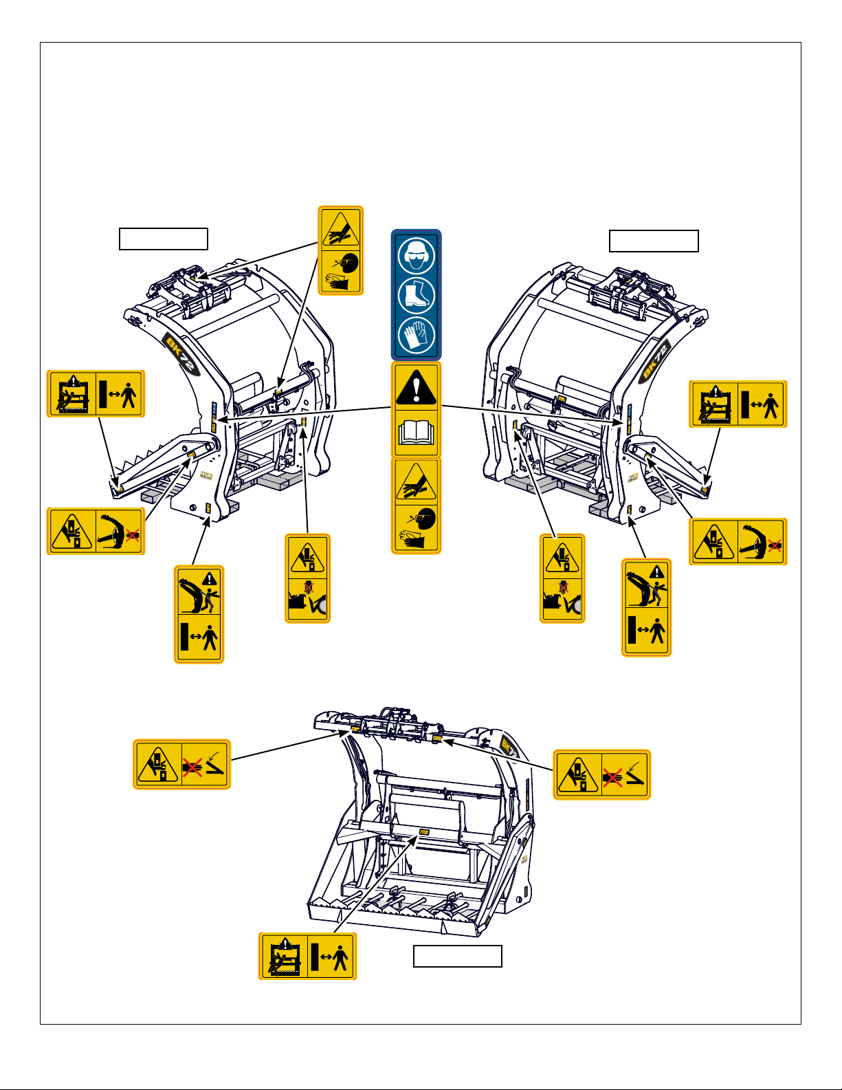
Safety Labels
Safety labeling is an important part of the overall safe use of the implement. Safety labeling alerts and warns against
potential injury or death, and is important to follow these points to help keep your implement safe for you and others who
may be using it.
If labels need to be replaced:
• Be sure that the installation area is clean and dry.
• Be sure temperature is above 50°F (10°C).
• Determine exact position before you remove the backing paper.
• Remove the smallest portion of the split backing paper.
• Align the sign over the specied area and carefully press the small portion with the exposed sticky backing in place.
• Slowly peel back the remaining paper and carefully smooth the remaining portion of the sign in place.
• Small air pockets can be pierced with a pin and smoothed out using the piece of sign backing paper.
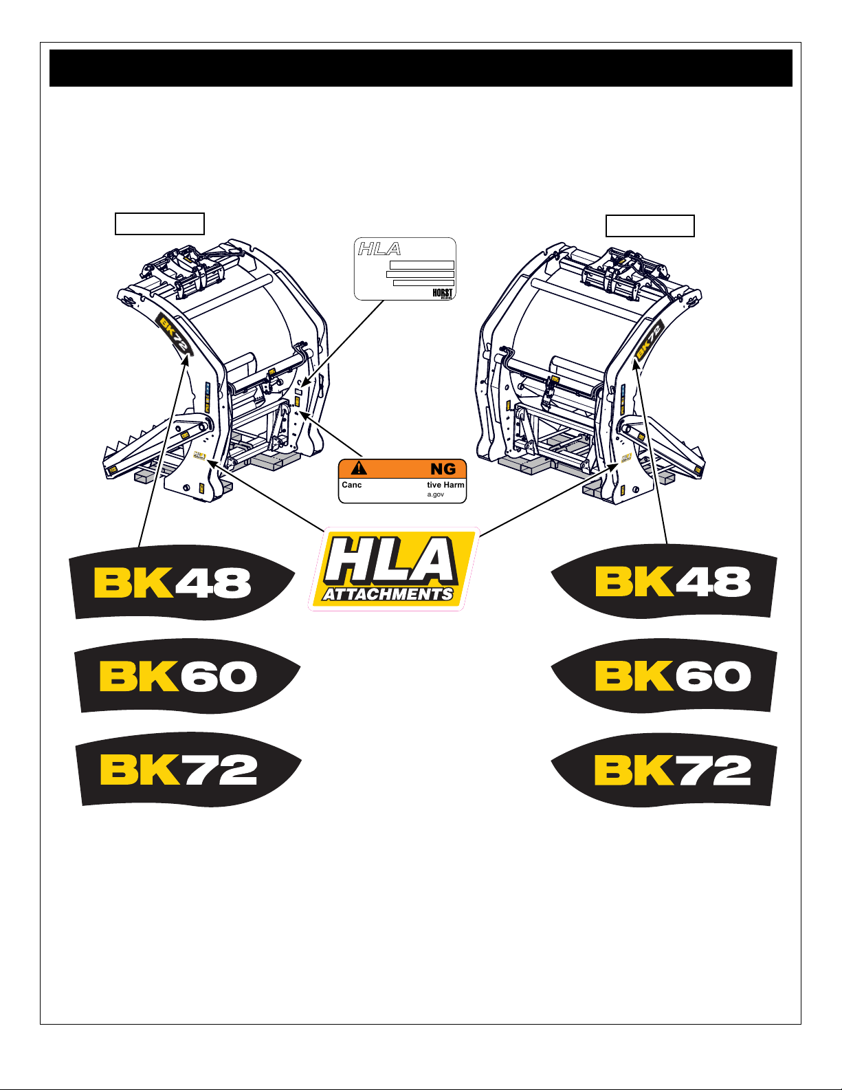
Safety Label Descriptions
• Keep safety signs clean and legible at all times.
• Replace safety signs that are missing or have become
illegible.
• Replaced parts that displayed a safety sign should
also display the current sign.
• Safety signs in Section 3 each have a part number
displayed with it. Use this part number when ordering
replacement parts.
• Safety signs are available from your authorized
Distributor or the factory order desk.
SL00008
SL00002
SL0010H
SL00004
SL00009H
SNL00001
Caution: read and understand ALL safety and
operating instructions in the manual, read and
understand ALL safety labels located on the
machine. The most important safety device on
this equipment is an informed SAFE operator.
Caution: be aware of sharp cutting arm
blades and tines. Cutting arm must aways
be stored in the up position. Use caution
and keep distance when walking around
the blades and tines. Possible tripping hazard
could result in death or serious injury from
laceration or impact.
Caution: Moving parts present a potential pinch
hazard and could result in a serious injury.
Use caution and be aware of parts as they are
being moved or adjusted. Possible pinching or
crushing hazard.
Caution: Moving cutting arm assembly
presents a potential pinch hazard and
could result in a serious injury. Use caution
and be aware of the arm as it moves up
and down. Possible pinching or amputation.
Caution: Personal Protection Equipment (PPE)
is required when operating or maintaining this
machine. Failure to wear PPE will result in
personal injury.
Caution: Hydraulic uid is under pressure, be
aware that hydraulic leaks could develop with
out warning. . Do not check for leaks with your
hand or ngers while the system is pressurized,
serious injury could result. Possible burns or
poisoning from pressurized uid injection.
SL00015
Caution: do not detach or store the bale knife
without placing it to the shipping / storage stand.
The BK is unstable in this position and could tip
without warning and serious injury could result.
Possible crushing or broken bone hazard.
SL00022
Caution: do not place your hand or any part
of your body on or near the front mount while
coupling to the power unit. Parts moving
together present a pinch point and may cause
serious injury Possible laceration, crushing,
amputation hazard.
Chassis parts lists for this product can be found online. Visit hlaattachments.com and click on the PARTS tab to be
directed to our online parts catalogue.
Parts List