Ohlins RXF34 m.2 Instruction manual

Workshop Manual - Chassis and Air Spring 100 h service
Front Fork
RXF34 m.2/RXC34 m.1

2
© Öhlins Racing AB. All rights reserved.
Any reprinting or unauthorized use without the written
permission of Öhlins Racing AB is prohibited.
General Warnings
Note!1
When working with the Öhlins product, always read the Vehicle Service Manual.
Note!1
The shock absorber/front fork/steering damper is an important part of the vehicle
and will affect the stability.
Note!1
Read and ensure you understand the information in this manual and other
technical documents provided by Öhlins, before using or servicing the product.
Note!1
Öhlins Racing AB can not be held responsible for any damage to the shock
absorber/front fork/steering damper, vehicle, other property or injury to persons, if
the instructions for mounting, usage and maintenance are not followed exactly.
Warning!⚠
After installing the Öhlins product, take a test ride at low speed to ensure your
vehicle has maintained stability.
Warning!⚠
If the suspension makes an abnormal noise, or the function is irregular, or if you
notice any leakage from the product, stop the vehicle immediately and return the
product to an Öhlins Service Centre.
Warning!⚠
The product warranty shall only apply if the product has been operated and
maintained in accordance with recommendations in this manual. If you have any
questions regarding usage, service, inspection and/or maintenance please contact
Öhlins.
Note!1
Before working on the product make sure that the vehicle is washed and cleaned
properly. Do not use alcobased products on the outside or inside of the product.
Product Specic Warnings
Warning!⚠
This product was developed and designed exclusively for a specic vehicle model
and shall only be installed on the intended vehicle model in its original condition as
delivered from the vehicle manufacturer.
Warning!⚠
This product is pressurized. Do not open, service or modify this product without
proper education (authorized Öhlins dealer/distributor) and proper tools.
Caution!✋
Do not use a pressure washer or a power washer when cleaning the fork.
SAFETY SYMBOLS
In this manual, mounting instructions and other technical documents,
important information concerning safety is distinguished by the following
symbols:
The Safety Alert Symbol means: Warning! Your safety is involved.
Warning!⚠
The Warning Symbol means: Failure to follow warning instructions can result
in severe or fatal injury to anyone working with, inspecting or using the shock
absorber/front fork, or to bystanders.
Caution!✋
The Caution Symbol means: Special precautions must be taken to avoid
damage to the shock absorber.
Note!1
The Note Symbol indicates information that is important regarding procedures.
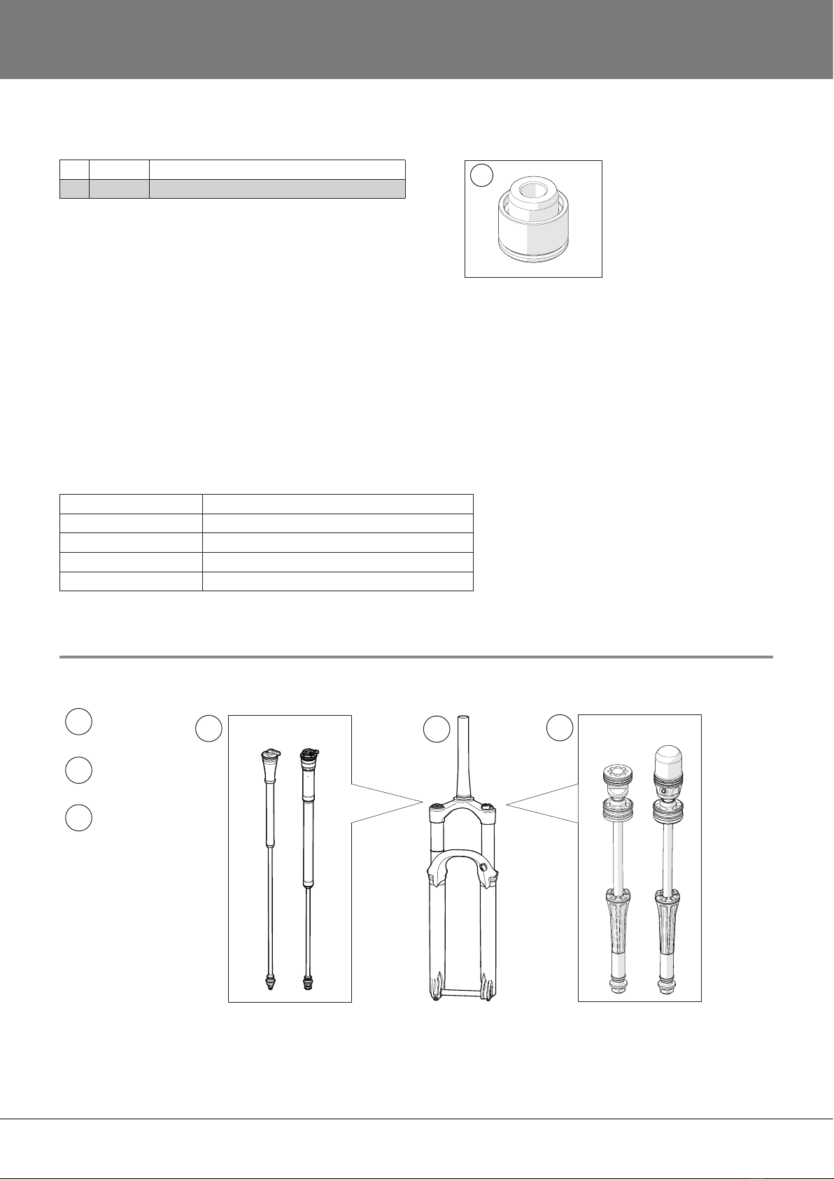
Table of Contents
Tools ...................................................................................................3
Overview - General layout..................................................................3
Chassi 100-Hour Service....................................................................5
Air spring Cartridge 100-hour service.................................................9
Appendix A. RXF34 m.2/ RXC34 m.1...............................................16
Appendix B. RXC34 m.1 Carbon......................................................17
SAFETY PRECAUTIONS

3
Tools
Oil, grease
Damper uid 01309-01 - High performance suspension uid 1L
Fork lubrication uid 01336-01 - Renep CGLP 68 Fork lube 1L
Air spring lubrication uid 01337-06 - Renep CGLP 220 Air spring lube 0.6L
Function grease 01338-22 - Renolit SI 410 M Silicone grease 225g
Assembly grease Slickoleum / Buzzy’s Slick Honey
1
Overview - General layout
1
2
3
12
3
Chassis
Damper
Cartridge
Air Spring
Cartridge
119246-03 Wiper seal tool 34
2 - Cassette lockring tool
RXC34OTX18 RXF34OTX14
RXF34 M.2/RXC34 M.1 FRONT FORK 100 H SERVICE

4
Service kit contents
119542-01 Service kit chassis RFX34
219547-01 Air spring 31 RFX 34 100 h service kit
RXF34 M.2/RXC34 M.1 FRONT FORK 100 H SERVICE
1
2
01027-25
(X-ring 23.39x3.53 NBR70)
19525-01
(Back-up ring 25.5/30.9/1.35)
00338-57
(O-ring 9.1x1.6)
00329-21
(Circlip 33.2x1)
00638-62
(O-ring 26.7x1.78)
00638-85
(O-ring 25x3)
19528-01
(Circlip 31 HHM-31)
x 2

5
RXF34 M.2/RXC34 M.1 FRONT FORK 100 H SERVICE
Chassi 100-Hour Service
1
Note!1
Record the rebound adjuster setting and the pressure in the positive air chamber
before service. We recommend using a bike stand to clamp the steering tube when
working on the fork.
1. Thoroughly clean the outside of the fork from dirt or grit.
2. Release all the air from the main chamber and the negative
chamber by holding the fork extended in the transfer position. Tip!
When almost all air is released from the spring, let go of the lower
and let it compress about 30 mm until all the pressure is gone. This
will help with getting the seal head out.
3. Measure and record LSC, HSC and Rebound clicks.
4. Applies for RXF34 only: Use a 14 mm wrench to hold back the
rebound adjuster knob steady. With a 2 mm hex wrench remove the
screw and the knob.
5. Remove the nut on both sides by using a socket wrench with a
14 mm deep hex socket.
6. Slide the lower legs off the stanchions.
7. Drain the lower legs of all uids.
4
3
5
2

6
RXF34 M.2/RXC34 M.1 FRONT FORK 100 H SERVICE
8
9
8. Use tweezers to cautiously remove the foam rings in the lower
legs.
9. Soak the new foam rings in fresh fork lubrication uid.
10. Use a screwdriver or similar to remove the old wiper seals.
Note!1
Be careful not to scratch the bushings or sealing surfaces in the lowers.
11. Use a rag wrapped around a long rod or similar to clean the
insides of the lower legs.
Note!1
Be careful not to scratch the bushings.
10
11

7
RXF34 M.2/RXC34 M.1 FRONT FORK 100 H SERVICE
12. Carefully clean the wiper seal and foam ring areas using disc
brake cleaner and a paper cloth or rag to remove old suspension
uid and dirt.
13. Reinstall new wiper seals into the lower legs. Use the wiper seal
tool and a soft hammer to put them in place.
14. Use tweezers to carefully insert the soaked foam rings into the
lower legs. Check that they are mounted corrrectly and not twisted.
14
12
13

8
RXF34 M.2/RXC34 M.1 FRONT FORK 100 H SERVICE
15. Hold the lower legs upside down and use a soft rag inside the
wiper seals to wipe of any oil residues from previous step.
16. Apply a thin layer of function grease to the inner surfaces of the
wiper seals.
17. Remove the old sag o-ring.
18. Install a new sag o-ring from the service kit.
19. Clean the stanchion tubes with a paper cloth or soft rag.
16
15
19
17
18

9
RXF34 M.2/RXC34 M.1 FRONT FORK 100 H SERVICE
Air spring Cartridge 100-hour service
Note!1
Clean all parts using disc brake cleaner and a rag to remove dirt, old grease and
thread sealant before reassembling. Lubricate new o-rings/x-rings etc. with fresh
assembly grease if no other grease is specied.
1. Ensure that there is no pressure left in the air spring by
depressing the schrader valve.
2. Place the fork in a vice.
3. Use a socket wrench with a cassette lockring socket to loosen
the air spring top cap.
4. Remove the old o-ring (00638-62) from the top cap.
5. Install the new o-ring (00638-62) on the top cap.
3
4 5
2

10
RXF34 M.2/RXC34 M.1 FRONT FORK 100 H SERVICE
6
6. Remove the screws with a 2 mm hex key.
7. Slide the seal head cap out of the tube. Remove the circlip
(19528-01) and discard it. Be carefull not to scratch the piston rod.
8. Pull on the piston rod gently until the seal head comes out.
Note!1
Clean all parts using disc brake cleaner and a rag to remove dirt, old grease and
thread sealant before reassembling. Lubricate new o-rings/x-rings etc. with fresh
assembly grease if no other grease is specied.
9. Remove the inner circlip (00329-21) and discard it.
8
7
9

11
RXF34 M.2/RXC34 M.1 FRONT FORK 100 H SERVICE
10. Remove the air spring from the stanchion.
11. Remove the o-ring (00638-85) from the seal head (Only RXF34
m.2 Air spring shown in picture.).
12. Remove the back-up rings (19525-01) and the X-ring (01027-25)
from the piston.
13. Carefully clean the piston using disc brake cleaner and a paper
cloth or rag to remove old grease and dirt.
14. Remove the o-ring (00338-57) from the rod end.
11
12
14
10
13

12
RXF34 M.2/RXC34 M.1 FRONT FORK 100 H SERVICE
Note!1
Clean all parts using disc brake cleaner and a rag to remove dirt, old grease and
thread sealant before reassembling. Lubricate new o-rings/x-rings etc. with fresh
assembly grease if no other grease is specied.
15. Clean the inside of the stanchion tube using disc brake cleaner
and a soft rag. Use a rod to push the rag thru the stanchion. Be
careful not to scratch the surface of the stanchions.
16. Apply a small amount of function grease all around the new
x-ring (01027-25) and the new back-up rings (19525-01).
17. Install the new x-ring (01027-25) on the piston.
18. Install the new back-up rings (19525-01) on the piston.
19. Install the new o-ring (00638-85) on the seal head.
20. Install the new o-ring (00338-57) on the rod end.
15
20
19
18
17
16

13
RXF34 M.2/RXC34 M.1 FRONT FORK 100 H SERVICE
Note!1
Clean all parts using disc brake cleaner and a rag to remove dirt, old grease and
thread sealant before reassembling. Lubricate new o-rings/x-rings etc. with fresh
assembly grease if no other grease is specied.
21. Reinstall the top cap and volume spacers. Use a torque wrench
with a cassette lockring socket to tighten the top cap to 32 Nm.
22. Apply 2 ml of function grease at the inside of the stanchion tube
inside the two circlip grooves (air spring side) (smeared around).
Add 1 ml of air spring lubrication uid distributed on top of the
grease.
23. Apply a thin layer of function grease on the X-ring and the back-
up rings on the piston.
24. Insert the piston into the stanchion tube, depressing the
schrader valve to relieve the pressure.
25. Install the new circlip (00329-21) in the inner most circlip groove.
Be carefull not to damage the Stanchion tube surface while installing
the circlip.
Note!1
Clean all parts using disc brake cleaner and a rag to remove dirt, old grease and
thread sealant before reassembling. Lubricate new o-rings/x-rings etc. with fresh
assembly grease if no other grease is specied.
26. Apply 1 ml of air spring lubrication uid inside the negative
chamber.
21
22
23 24
25
26

14
RXF34 M.2/RXC34 M.1 FRONT FORK 100 H SERVICE
27. Gently push the seal head into the stanchion tube. It should
come to a rm stop about 6 mm from the edge of the stanchion tube
if the inner circlip (00329-21) is properly seated.
Important! Clean the outer most circlip groove from any
remaining grease using a rag and disc brake cleaner. Failing to
do so might cause the circlip not to seat itself properly in the
groove.
28. Install the new circlip (19528-01). Be careful not to damage the
piston rod surface while installing the circlip.
Important! Make sure the circlip is properly seated in the
groove before continuing.
29. Reinstall the seal head cap with a 2 mm hex key. Tighten to
1.3 Nm.
30. Clean the stanchion tubes with a paper cloth or soft rag.
31. Inate the main chamber to the desired air pressure and cycle
the spring until the main and negative chamber pressures are
equalized.
32. Reinstall the lower legs on to the stanchions.
27
29
28
32
30 31

15
RXF34 M.2/RXC34 M.1 FRONT FORK 100 H SERVICE
33. Inject uids in spring and damper fork leg according to table
below. The volumes are critical as they will affect fork performance.
Damper fork leg Spring fork leg
Model Fork part no. Oil Volume Oil Volume
RXF34 m.2
RXC34 m.1
FGxxx 34xx 22xx
FGxxx 34xx 23xx
Damper uid 10 ml Fork lubrication uid 10 ml
See appendix A and B to detemine the part no. of the fork.
34. Reinstall the nuts. Use a torque wrench with a 14 mm hex
socket and tighten to 10 Nm.
35. Only RXF34: Reinstall the rebound adjuster knob and screw.
Use a 14 mm wrench to hold the knob steady. With a 2 mm hex
wrench tighten the screw and knob.
36. Adjust the rebound setting according to the value recorded.
37. Adjust the LSC and HSC setting according to the values
recorded.
38. Replace the air valve lid.
34
35
36
33
38

16
RXF34 M.2/RXC34 M.1 FRONT FORK 100 H SERVICE
Appendix A. RXF34 m.2/ RXC34 m.1
Part no of the fork can be found at the bottom
of the steerer tube.
The part no of the fork can also be found on
the steerer tube as a QR-code. Use a QR-code
reader in a smartphone to receive the part no.

17
RXF34 M.2/RXC34 M.1 FRONT FORK 100 H SERVICE
Appendix B. RXC34 m.1 Carbon
Part no of the fork can be found
on bearing surface ring.

Your Öhlins retailer:
Phone: +46 (0)8 590 025 00
Fax: +46 (0)8 590 025 80
www.ohlins.com
Öhlins Racing AB
Box 722
SE-194 27, Upplands Väsby
Sweden
Workshop Manual 100h RXF34 m.2/RXC34 m.1 Issued 2023-09-21 © Öhlins Racing AB
Other manuals for RXF34 m.2
1
This manual suits for next models
1
Table of contents
Other Ohlins Bicycle Accessories manuals
Popular Bicycle Accessories manuals by other brands

Rose electronics
Rose electronics BIKE.BOX 2.0 owner's manual

Bosch
Bosch Nyon operating instructions

Crivit
Crivit SP-107 owner's manual

Cannondale
Cannondale 120027.PDF Owner's manual supplement

Continental Refrigerator
Continental Refrigerator XT Series Original instructions

BOS Suspension
BOS Suspension RARE FCV Series user manual