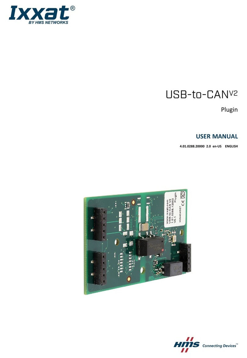
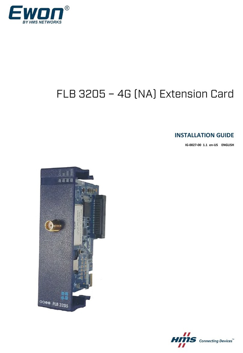
HMS Anybus AS-Interface Master User manual

How to configure an Anybus AS-Interface Master module
SCM-7032-036
Rev 1.02
How to configure an Anybus AS-Interface
Master module
www.anybus.com HMS Industrial Networks AB
Page 1 (19)

How to configure an Anybus AS-Interface Master module
SCM-7032-036
Rev 1.02
www.anybus.com HMS Industrial Networks AB
Page 2 (19)
More info about the network and products
This document gives a brief description of how to configure an Anybus Master product for AS-Interface. For
further information about the products, please consult the HMS homepage, www.anybus.com. The latest
manuals etcetera can be downloaded from that location.
For more information regarding AS-Interface network please see the AS-Interface webpage,
http://www.as-interface.net.
Document history
Revision Date Description Responsible
1.00 2008-01-25 Created Thorbjörn Palm
1.01 2008-02-04 Minor revision Thorbjörn Palm
1.02 2008-02-15 Minor update Thorbjörn Palm

How to configure an Anybus AS-Interface Master module
SCM-7032-036
Rev 1.02
www.anybus.com HMS Industrial Networks AB
Page 3 (19)
Contents
1Solution overview .....................................................................................................................................4
2Applicable Anybus products ...................................................................................................................5
3Requirements ............................................................................................................................................5
4Anybus configuration...............................................................................................................................6
4.1 Anybus-M Master and PCI Master configuration.............................................................................6
4.2 Anybus X-gateway configuration .....................................................................................................7
5AS-Interface configuration......................................................................................................................9
5.1 Configuration using the Configuration Button .................................................................................9
5.2 Configuration using the Terminal Interface....................................................................................10
5.3 Memory Mapping ...........................................................................................................................14
6Testing .....................................................................................................................................................15
6.1 Monitoring using the Terminal Interface ........................................................................................15
6.2 Monitoring using ModScan32 ........................................................................................................18
6.3 Web interface..................................................................................................................................19

How to configure an Anybus AS-Interface Master module
SCM-7032-036
Rev 1.02
1Solution overview
This application note describes how to configure an Anybus AS-Interface Master module and how to set up
the AS-Interface network. Below you can find an overview of the system described in this document. Other
nodes may be attached to the network, but are not necessary.
The configuration is described in two steps.
1. The Anybus Master module configuration is explained.
2. The configuration of the AS-Interface network is described.
Note: This document is valid for all Anybus AS-Interface Master products, however sections written in
italics describe the configuration of a specific product.
The contents describe step by step how a configuration is done. This document assumes the reader is familiar
with industrial communication, AS-Interface networks and Anybus X-gateway.
Modbus-TCP
Anybus X-gateway
Other network
i.e. Modbus-TCP
AS-Interface
Master
Example of AS-Interface
network
AS-Interface
PC
ModScan
AS-Interface
Anybus AS-Interface
Master PCI
Figure 1 Hardware connection overview.
www.anybus.com HMS Industrial Networks AB
Page 4 (19)

How to configure an Anybus AS-Interface Master module
SCM-7032-036
Rev 1.02
www.anybus.com HMS Industrial Networks AB
Page 5 (19)
2Applicable Anybus products
The following table specifies the relevant Anybus products for this document.
Description Name / Type
Anybus-M Master AS-Interface (Module software version higher than 2.04)
Anybus-M Master PCI AS-Interface (Module software version higher than 2.04)
Anybus X-gateway Master AS-Interface (Module software version higher than 2.04)
3Requirements
The following equipment is needed to setup a successful configuration.
Description Name / Type Version
Terminal software HyperTerminal, TeraTermPro 5.1, 2.3
X-gateway Interface Addendum X-gateway AS-Interface Master
Interface Addendum
2.10
X-gateway User Manual X-gateway User Manual 1.11
Master Fieldbus Appendix Anybus-M Master AS-Interface
Fieldbus Appendix
2.00
Power supply 24VDC n.a. n.a
Configuration cables n.a. n.a.

How to configure an Anybus AS-Interface Master module
SCM-7032-036
Rev 1.02
www.anybus.com HMS Industrial Networks AB
Page 6 (19)
4Anybus configuration
In the following chapters the configuration of the Anybus-M Master, PCI Master and X-gateway
AS-Interface Master are explained.
4.1 Anybus-M Master and PCI Master configuration
The Anybus-M Master and Anybus PCI Master are configured via the host application interface using the
mailbox interface. Refer to the Anybus-M Fieldbus Appendix for details.
The Anybus AS-Interface Master can also be auto configured by the Configuration Button and the Terminal
Interface. Please see section 5 AS-Interface configuration for details.

How to configure an Anybus AS-Interface Master module
SCM-7032-036
Rev 1.02
4.2 Anybus X-gateway configuration
Use the HyperTerminal on a PC to configure the X-gateway. Connect a serial cable between the PC and the
config port on the X-gateway (make sure that it is not connected to the AS-Interface Master). Start the
HyperTerminal and open the “File” menu and click on new, choose the desired COM port and then click on
OK. The following window will appear.
Figure 2 Configuring the connection in the HyperTerminal.
Make sure the settings are identical to those shown in the window above. Alternatively download a
HyperTerminal session file from the HMS website1, double click on it and select COM port.
Connect and press ESC and the following menu will appear.
Figure 3 Anybus X-gateway main menu.
Press 6 and enter the desired configuration.
1www.anybus.com
www.anybus.com HMS Industrial Networks AB
Page 7 (19)

How to configure an Anybus AS-Interface Master module
SCM-7032-036
Rev 1.02
The figure below shows an example; in this case an AS-Interface Master to Modbus-TCP Slave X-gateway is
used. 20 bytes of I/O data on the Modbus-TCP side and 312 bytes of I/O data on the AS-Interface side are
configured. Also byte mode is used in this configuration.
Note: The Input and Output data size is always set to 312 bytes and cannot be changed.
Data Representation:
This mode can be set to Byte Mode
or Nibble Mode.
Figure 4 The X-gateway configuration.
The next step is to set the X-gateway in running mode.
Running: AS-Interface network is
running and exchanging data.
Idle DE Active: AS-Interface
network is idle, but the
communication is still active.
Idle DE Inactive: AS-Interface
network is idle and no data exchange
messages are issued.
Figure 5 Changing Operation mode of the X-gateway.
Choosing 9 from the main menu the X-gateway can be set to Running, Idle DE Active or Idle DE Inactive.
Set the Operation Mode to Running.
www.anybus.com HMS Industrial Networks AB
Page 8 (19)

How to configure an Anybus AS-Interface Master module
SCM-7032-036
Rev 1.02
www.anybus.com HMS Industrial Networks AB
Page 9 (19)
5AS-Interface configuration
The AS-Interface Master configuration can be done in several ways.
1 The Configuration Button enables the auto configuration as described in section 5.1 Configuration using
the Configuration Button.
2 The Terminal Interface can also be used to configure the AS-Interface Master as described in section 5.2
Configuration using the Terminal Interface. Using this alternative it is possible to change the slave
parameters.
3 The configuration can also be done by using mailbox commands. Please see the Master Fieldbus
Appendix. Note: This alternative is usable only by Anybus-M AS-Interface Master and Anybus-M PCI AS-
Interface Master.
In the end of this chapter, section 5.3 Memory Mapping, the memory mapping is described in detail.
5.1 Configuration using the Configuration Button
This alternative assumes the AS-Interface network is connected to the Anybus Master. Please follow the
steps below.
1Changing to Configuration mode using the Configuration Button
This is done by pressing the Configuration Button for less than 2 seconds, which will toggle the mode
between Configuration and Protected mode. The Module Status/MS LED is solid green in Configuration
mode.
2Pressing the Configuration Button to upload and save the network configuration
Push and hold the Configuration Button for more than 5 seconds, this will enable the Auto Configuration.
3Changing to Protected mode
Press the Configuration button again for less than 2 seconds to change the mode to Protected mode.
4Network running
If the configuration is successful the network is now online and running. The Running/RUN LED is now
solid green and Network Status/NS LED and Module Status LED are flashing green. Auto prog./AUP LED
is off indicating no error.

How to configure an Anybus AS-Interface Master module
SCM-7032-036
Rev 1.02
5.2 Configuration using the Terminal Interface
The AS-Interface Master can also be configured using the Terminal Interface. Please follow the steps below.
1Connecting to the AS-Interface with a Terminal software
Use for example the HyperTerminal or TeraTermPro on a PC to configure the AS-Interface Master. Connect
a serial cable between the PC and the config port on the AS-Interface Master (make sure that it is not
connected to the gateway interface). The config port is located next to the AS-Interface network connectors
on the X-gateway. Start the HyperTerminal and connect using the same parameter settings as described in
section 4.2 Anybus X-gateway configuration.
2Opening the main menu
Figure 6 Entering the menu of the AS-Interface Master.
Press enter to open the configuration menu. Now the module is set to Idle mode, until the terminal is
removed.
Figure 7 The main menu of the AS-Interface Master.
www.anybus.com HMS Industrial Networks AB
Page 10 (19)

How to configure an Anybus AS-Interface Master module
SCM-7032-036
Rev 1.02
3Changing to Configuration mode
Enter 5 in the main menu and change the mode to Configuration mode.
Figure 8 Changing the mode of the AS-Interface Master.
4Viewing all detected slaves.
Enter 3 in the main menu to view all detected slaves.
One slave with profile S-6.0.C, CTT5
Figure 9 Viewing all detected slaves on the AS-Interface network.
In this case 3 slaves are detected. The slaves 7 and 41 use both digital and analogue data. Slave 12 uses
digital data only. Enter the number of the individual slave to view the settings in detail.
www.anybus.com HMS Industrial Networks AB
Page 11 (19)

How to configure an Anybus AS-Interface Master module
SCM-7032-036
Rev 1.02
Figure 10 Viewing the slave settings.
The settings can now be changed if desired. In this case the settings are left at the default values.
5Saving the configuration.
The next step is to save the configuration. Enter 8 in the main menu to open the Save configuration menu.
Figure 11 Saving the configuration.
Then press Enter to save the configuration.
www.anybus.com HMS Industrial Networks AB
Page 12 (19)

How to configure an Anybus AS-Interface Master module
SCM-7032-036
Rev 1.02
6Changing to protected mode.
The final step is to change the operation mode to protected mode.
Figure 12 Changing the AS-Interface Master mode to Protected mode.
7Disconnecting the Terminal connection.
In the HyperTerminal press the disconnect button and disconnect the serial cable. The module now changes
to Running mode.
8Network running.
If the configuration is successful the network is now online and running. The Running/RUN LED is now
solid green and Network Status LED and Module Status LED are flashing green. Auto prog./AUP LED is off
indicating no error.
www.anybus.com HMS Industrial Networks AB
Page 13 (19)

How to configure an Anybus AS-Interface Master module
SCM-7032-036
Rev 1.02
5.3 Memory Mapping
The figure below shows the memory mapping of the AS-Interface Master generally.
Note: For the X-gateway the memory mapping will be different depending on if the Control Word, Status
Word and Live List are used. This info will be mapped before the digital I/O data, please see the X-gateway
Interface Addendum for details. The mapping is performed in the same way for both input and output data of
the X-gateway.
Nibble mode Byte mode
The figure to the left shows the memory
mapping of the AS-Interface Master. The
analogue data will always be mapped after
the digital data.
Figure 13 The memory mapping using the auto configuration.
The mapping of the analogue data is shown in the figure below.
Offset (byte) Word no. Description
0... 1 1 Analogue Input Data for slave 1, channel 0
2... 3 2 Analogue Input Data for slave 1, channel 1
4... 5 3 Analogue Input Data for slave 1, channel 2
6... 7 4 Analogue Input Data for slave 1, channel 3
8... 9 5 Analogue Input Data for slave 2, channel 0
10... 11 6 Analogue Input Data for slave 2, channel 1
12... 13 7 Analogue Input Data for slave 2B, channel 0
14... 15 8 Analogue Input Data for slave 2B, channel 1
... ..
246... 247 124 Analogue Input Data for slave 31, channel 3
When extended addressing is used,
for example slaves 2 and 2B,
the analogue data area is shared.
In other words slave 2 and 2B will
use 4 b
y
tes of analo
g
ue data each.
Figure 14 The mapping of the analogue I/O data.
www.anybus.com HMS Industrial Networks AB
Page 14 (19)

How to configure an Anybus AS-Interface Master module
SCM-7032-036
Rev 1.02
6Testing
The testing of the network can be done after finishing the configuration. In this particularly case the
AS-Interface Master to Modbus-TCP Slave X-gateway is used for test purpose.
The communication is tested in two ways. Firstly the data is monitored in the AS-Interface Master Terminal
Interface. This will verify that the AS-Interface network is exchanging data. Secondly the data is monitored
on the other network side of the X-gateway using ModScan32.
6.1 Monitoring using the Terminal Interface
Open the Terminal Interface again and select 3 in the main menu.
Note: When connected to the AS-Interface Master no data is written to the AS-Interface network.
Figure 15 Viewing all the detected slaves on the network.
Enter the slave address of interest and press enter.
www.anybus.com HMS Industrial Networks AB
Page 15 (19)

How to configure an Anybus AS-Interface Master module
SCM-7032-036
Rev 1.02
The window below shows the data values of slave 41. The marked data shows the analogue input from a
temperature sensor on the AS-Interface network.
Figure 16 Monitoring analogue I/O data using the Master Terminal Interface.
www.anybus.com HMS Industrial Networks AB
Page 16 (19)

How to configure an Anybus AS-Interface Master module
SCM-7032-036
Rev 1.02
In this case slave 7 is monitored. The marked data is digital input data.
Figure 17 Monitoring digital I/O data Master Terminal Interface.
www.anybus.com HMS Industrial Networks AB
Page 17 (19)

How to configure an Anybus AS-Interface Master module
SCM-7032-036
Rev 1.02
6.2 Monitoring using ModScan32
To verify that the data is exchanged between the two networks using the Anybus X-gateway, the program
ModScan32 is used.
Note: To use ModScan for testing is it is required that the gateway has an Ethernet connection.
Figure 18 Monitoring the I/O data using ModScan32.
The window above shows the I/O data from the AS-Interface nodes. The marked data is the digital I/O data
of slave 7 (register 0004H) and analogue I/O data from slave 41 (register 0043H). The data values are
corresponding to the data values seen in Figure 16 and Figure 17.
www.anybus.com HMS Industrial Networks AB
Page 18 (19)

How to configure an Anybus AS-Interface Master module
SCM-7032-036
Rev 1.02
6.3 Web interface
The configuration can also be verified using the web interface in the X-gateway.
Note: To use the web interface it is required that the X-gateway has an Ethernet connection. Use the Anybus
IPconfig to find or set the IP-address. The tool can be downloaded at www.anybus.com.
To enter the web interface, enter the IP-address of the Ethernet module in a web browser, e.g.
http://192.168.0.7. Open the Device Diagnostics window to view the slave settings.
Figure 19 Viewing the AS-Interface Diagnostics in the web interface.
In the next window, the General Status window, it is possible to view the X-gateway configuration.
Figure 20 Viewing the General Status in the web interface.
www.anybus.com HMS Industrial Networks AB
Page 19 (19)
Table of contents
Other HMS Control Unit manuals

HMS
HMS Ewon Flexy FLB 3205 User manual

HMS
HMS Ixxat USB-to-CANV2 User manual

HMS
HMS Anybus EtherNet/IP User manual
HMS
HMS Anybus CC-Link Slave Setup guide

HMS
HMS CM CANopen User manual

HMS
HMS Anybus User manual

HMS
HMS Anybus Communicator User manual

HMS
HMS IXXAT Safe T100 Installation and operating manual
HMS
HMS Anybus CompactCom 30 Guide

HMS
HMS Anybus CANopen Slave User manual