Chapter I purchase inspection .......................... 1
1.1 Check item ..............................................................1
1.2 Nameplate description .......................................... 2
1.2.1 Nameplate description .................................2
1.2.2 Frequency inverter model description ...... 2
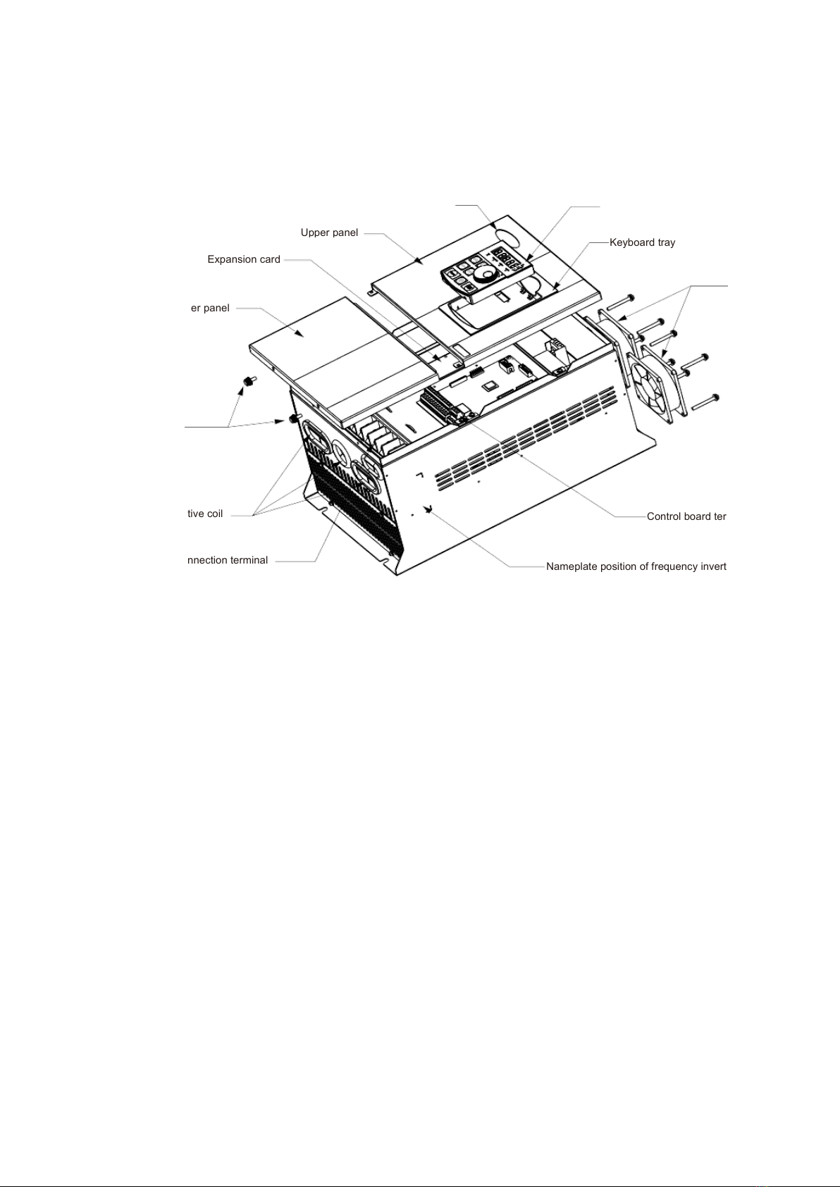
1.3 Description of parts of HV610 inverter ...............3
Chapter II Installation wiring ...............................4
2.1 Mechanical installation ......................................... 4
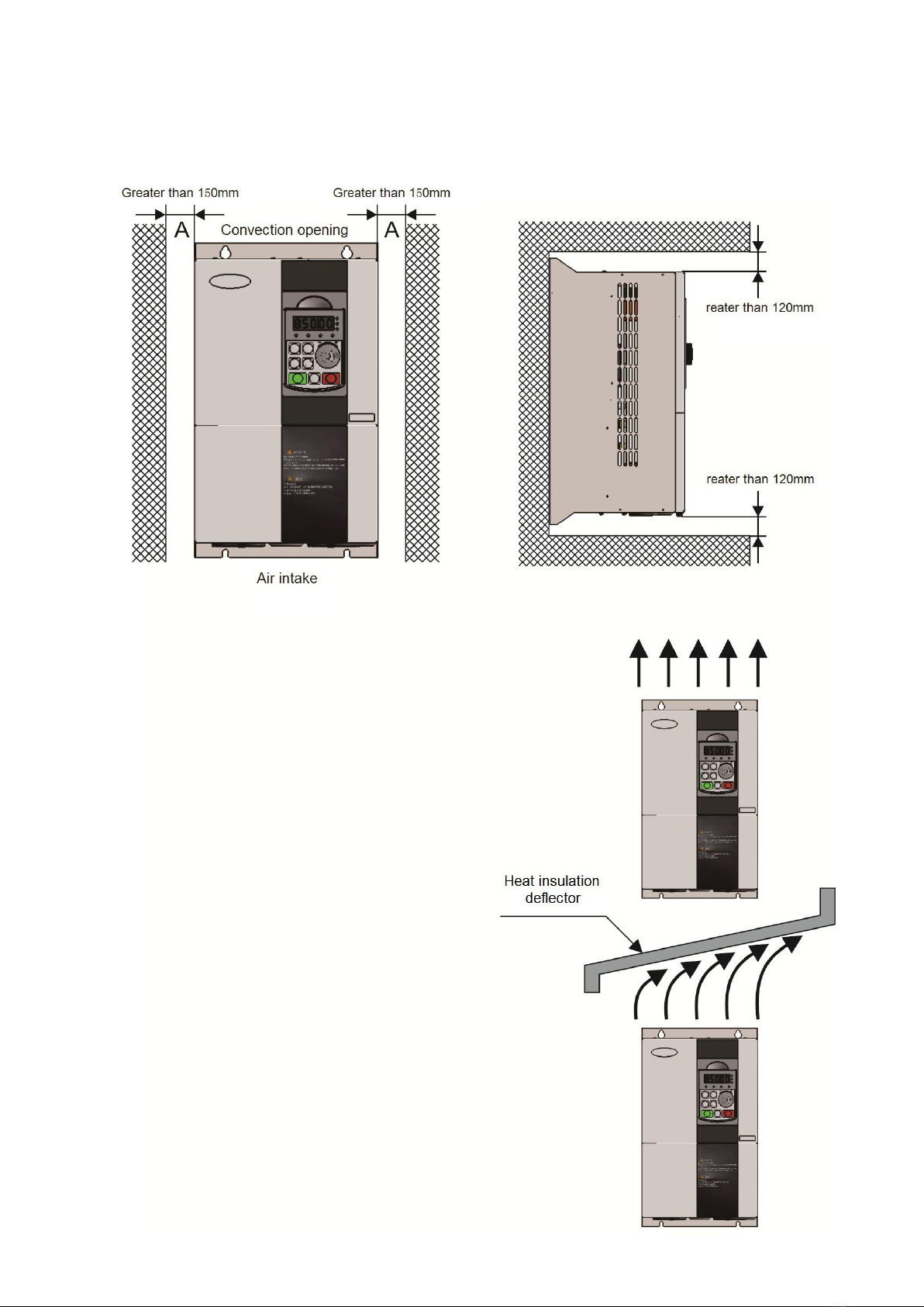
2.1.1 Installation Conditions ................................. 4
2.1.2 Installation Space .........................................5
2.2 Electrical Installation ............................................. 6
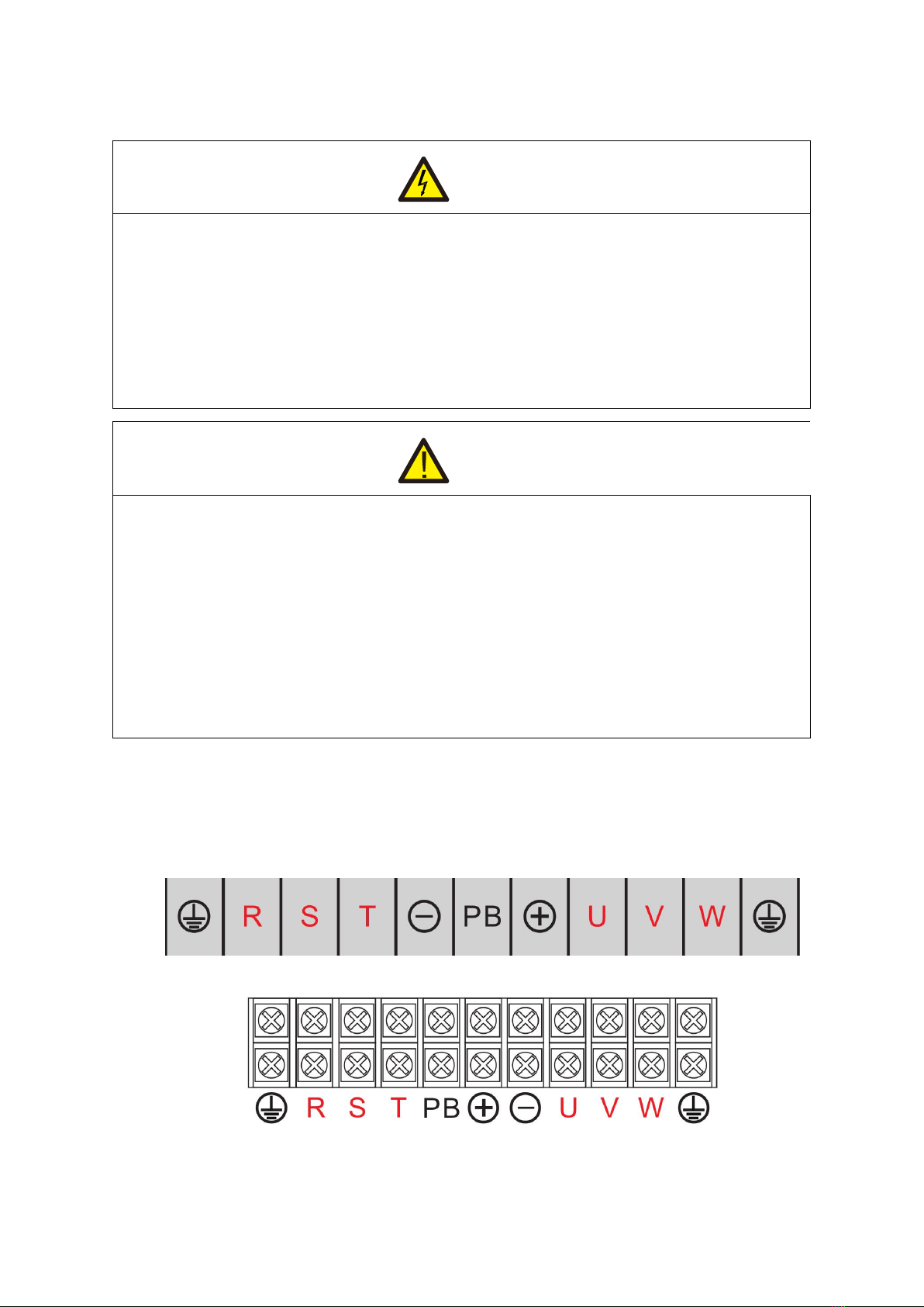
2.2.1 Frequency inverter main circuit terminal
description ............................................................... 6
2.2.2 Main circuit wiring method and wiring
precautions ..............................................................7
2.2.3 Frequency inverter control loop terminal
description ............................................................... 8
2.2.4 Standard wiring diagram of frequency
inverter ..................................................................... 12
2.2.5 Control loop connection mode ................... 13
Chapter III Process operation ............................ 16
3.1 operating keyboard and display interface ......... 16
3.2 indicator light description ......................................16
3.3 key function description ........................................ 17
3.4 methods for viewing and modifying function codes
...........................................................................................17
3.5 Two quick access modes for function code
parameters .................................................................... 18
3.6 trial running ............................................................. 18
3.7 motor characteristic parameter setting and
automatic tuning ........................................................... 18
Chapter IV Functional parameters ...................21
Chapter V Description of parameters ............ 54
F0 group basic function ...............................................54
F1 group motor parameters ........................................64
F2 group motor vector control parameters .............. 66
F3 group V/F control parameter .................................67
F4 group output terminal .............................................71
F5 group input terminal ............................................... 77
F6 group start-stop control ..........................................89
F7 group torque control .............................................. 94
F8 group auxiliary function .........................................95
F9 group fault and protection ...................................101
FA group PID function ...............................................106
FB group second group motor parameters ...........111
FC group multi-segment instruction, simple PLC 112
FD group communication parameters ................... 117
FE group user customized function code ..............117
FF group performance optimization parameters ..117
E0 group fault record ................................................ 117
P2 group AIAO correction group .............................119
U0 group monitoring parameter group ...................121
Chapter VI abnormal diagnosis ......................126
6.1 fault alarm and countermeasures .................... 126
6.2 matters needing attention in commissioning ..129
6.3 F0.01 = 2 V/F mode, common problem solving
methods.........................................................................130
6.4 fault analysis and countermeasures ................130
Chapter VII Maintenance .................................... 134
7.1 routine maintenance and safeguard ................134
7.2 product storage and storage .............................136
Chapter VIII Peripheral devices ...................... 137
8.1 introductions to configuration of peripheral devices
........................................................................................ 137
8.2 functional description of peripheral equipment
........................................................................................ 137
Chapter IX Quality Assurance ......................... 145
Appendix A Introduction of Communication
............................................................................................ 147
Appendix B: Technical specification for
frequency inverters ............................................... 159
Appendix I general purpose keyboard
dimensions and mounting dimensions ..... 161
Appendix II Plastic shell dimensions and
mounting dimensions............................................ 162
Appendix III dimensions and mounting
dimensions of sheet metal machines............162
Constant pressure control solution Case V0.1
for water pump and fan......................................... 170


 User manual")


