manuals.online logo
Brands
  1. Home
  2. •
  3. Brands
  4. •
  5. Festo
  6. •
  7. DC Drive
  8. •
  9. Festo DFPI-...D2P-C1V-NB3P series User manual

Festo DFPI-...D2P-C1V-NB3P series User manual

Linear drive
DFPI-…-ND2P-C1V-NB3P-A
Festo AG & Co. KG
Postfach
73726 Esslingen
Germany
+49 711 347-0
www.festo.com
(en)Operating instructions 8062742
1608
[8062744]
Original: de
Linear drive DFPI-…-ND2P-C1V-NB3P-… English...........................
1 Configuration
1
2
3
aA
aB
aJ
4
5
6
7
5
8
9
1Housing
2Electrical and pneumatic connec
tion (under the protective cap)
3End cap
4Bearing cap
5Mounting interface in accordance
with ISO 15552
6Air duct
7Pressure compensation element
8Earth terminal
9Flow control screw
aJ Piston rod with mounting thread
for accessories
aA Spanner flat
aB Tie rod
Fig. 1
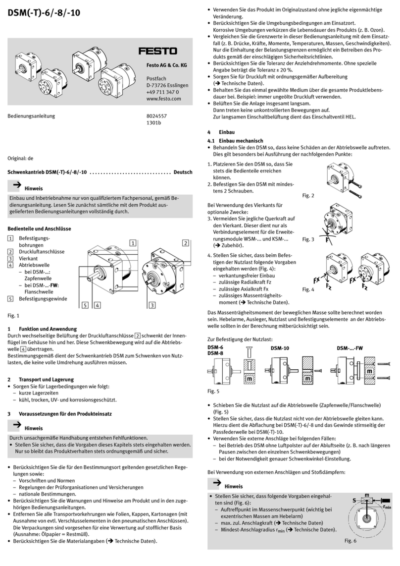
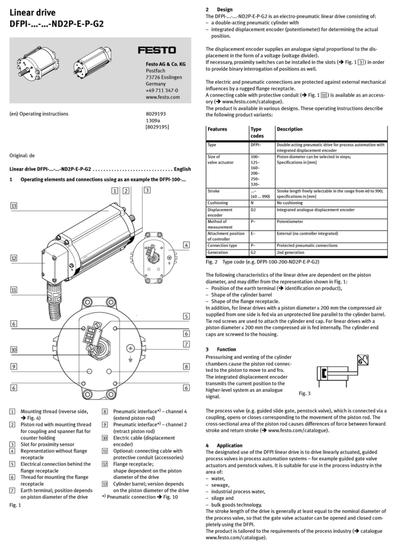
The DFPI-…-ND2P-C1V-NB3P- is an electropneumatic linear drive consisting of:
– a double-acting pneumatic cylinder with
– integrated displacement encoder (potentiometer) for determining the actual
position
– integrated valve block with directional control valves for controlling the piston rod
– integrated positioner for position control.
Proximity sensors can be screwed onto the tie rods if necessary for additional bin
ary sensing of positions.
A pressure compensation element prevents the formation of condensate inside the
housing in the event of temperature fluctuations, thus protecting the internal elec
tronics.
For DFPI-…-ND2P-C1V-NB3P-... the electrical and pneumatic connections are pro
tected against external mechanical influences by a rugged flange receptacle.
The compressed air supplied from one side is fed via an unprotected line parallel
to the cylinder barrel. Tie rod screws are used to attach the cylinder end cap.
Accessories èwww.festo.com/catalogue.
Feature Type code Description
Type DFPI Regulated drive for process automation
Piston diameter 100, 125, 160, 200,
250, 320
Specifications in [mm]
Stroke ... Stroke length freely selectable in the range from
40 to 990; specifications in [mm]
Function Not specified Double-acting
Cushioning N No cushioning
Displacement en
coder
D2 Analogue
Method of measure
ment
P Potentiometer
Regulation C1 Controller 1
Directional control
valve
V Integrated
Standard NB3 Based on ISO 155522
Connection type PProtected pneumatic connections
Safety position Not specified
R
Piston rod advancing
Piston rod retracting
Feedback A Analogue feedback
Fig. 2 Type code (e.g. DFPI-100-200-ND2P-C1V-NB3P-A)
2 Safety
Intended use
The DFPI-…-ND2P-C1V-NB3P-... linear drive is intended for regulation in process
engineering systems. It is particularly appropriate for pneumatic positioning under
rough operating conditions.
 Only use the product in its original status, without any unauthorised modifications.
 Only use the product if it is in perfect technical condition.
 Use only proximity sensors approved for the product.
 Take into consideration the ambient conditions at the location of use.
 Observe the specifications on the product labelling.
 Comply with all applicable national and international regulations.
Operating medium
 Only use compressed air in accordance with the specifications (èChapter 11).
 Only use unlubricated compressed air under normal conditions. Once the
product has been used with lubricated compressed air, it must continue to be
operated with compressed air only.
Drive
Impermissible lateral forces on the piston rod can damage the rod bearing or the
linear drive.
 Do not exceed the maximum permissible lateral forces on the piston rod
(èFig. 11).
 Guide the piston rod, if necessary, to avoid start-up oscillations.
Return to Festo
Hazardous substances can endanger the health and safety of personnel and cause
damage to the environment. To prevent hazards, the product should only be re
turned upon explicit request by Festo.
 Consult your regional Festo contact.
 Complete the declaration of contamination and attach it to the outside of the
packaging.
 Comply with all legal requirements for handling hazardous substances and
transporting dangerous goods.
3 Function
The compressed air applied at connection P
is directed by the integrated valve block al
ternately to the two piston chambers of the
cylinder – depending on the setpoint posi
tion that is specified. This causes the piston
rod connected to the piston to move
backwards and forwards. Fig. 3
The maximum possible venting of the two cylinder chambers can be set independ
ently of each other using flow control screws D2 and D4. D2 controls the venting
flow when the piston rod advances. D4 controls the venting flow when the piston
rod retracts. This can be used to control the maximum travel speed of the linear
drive in the range from 0 %...100 %. In the factory setting, the flow control screws
are completely open.
Positions are specified via an analogue setpoint signal (4…20 mA). The piston rod
is positioned in a controlled manner.
The integrated positioner performs position control of the piston rod within the
available stroke range.
The integrated displacement encoder transmits the current position to the internal
positioner as an analogue signal. The positioner cyclically compares the setpoint
and actual positions and transmits appropriate positioning signals to the integ
rated valve block for positioning control.
The valve block controls the desired direction of movement by pressurising the one
cylinder chamber and simultaneously venting the other cylinder chamber.
The current position is provided as an analogue current signal (4 … 20 mA) via the
actual value output and can be evaluated by a higher-order controller if needed.
The drive has a factory-defined safety position. It responds as follows if the operat
ing voltage supply or the analogue setpoint is outside of the permitted range (e.g.
in the event of a wire break):
– DFPI-…-ND2P-C1V-NB3P-A:
Piston rod is advanced (close process valve).
– DFPI-…-ND2P-C1V-NB3P-R-A:
Piston rod is retracted (process valve opens).
4 Transport and storage
Warning
Danger of crushing! Danger of shearing!
The product weighs up to 60 kg, depending on the product version.
Body parts can be crushed or cut off if the product falls.
 Use appropriate load handling equipment.
 Do not use the air duct as a handle for carrying.
 When shipping used products: Comply with all legal requirements for handling
hazardous substances and transporting dangerous goods. For return to Festo
èChapter 2.
 Remove all attachments.
 Store the product in a cool, dry, UV- and corrosion-protected environment. En
sure storage times are short.
5 Installation
Note
Installation should only be conducted by qualified specialized personnel.
5.1 Mechanical installation
It can be mounted in any position.
1. Remove all transport packaging. The material used in the packaging has been
specifically chosen for its recyclability (exception: oil-impregnated paper =
residual waste).
2. Fasten the drive with the mounting screws on the bearing cap/end cap (mounting
interface in accordance with ISO 15552). Tighten the mounting screws evenly.
– Tightening torques èFig. 4.
Piston diameter Tightening torque [Nm]
100 10
125 24
160 70
200 70
250 150
320 250
Fig. 4
When using additional proximity sensors
Note
When linear drives are installed too close to each other, the cylinder magnet can
disturb the proximity sensor on the adjacent linear drive.
1. Fasten sensor bracket to the tie rod.
– Tightening torque 0.6…1 Nm.
2. Mount proximity sensor (èProximity sensor operating instructions).
3. Check minimum distances to ferritic and magnetic materials. Place the drive so
that trouble-free operation is possible.
4. Fasten the drive.
When mounting accessory parts on the piston rod
1. Attach accessories to the male thread of the piston rod (èFig. 1, aJ ).
2. Tighten nut and accessories.
5.2 Electrical installation
Warning
For the electrical power supply, only use PELV circuits in accordance with
IEC/EN 60204-1. Only use power sources which guarantee reliable electrical
isolation of the operating voltage in accordance with IEC/EN 60204-1.
The electrical connection is covered by the housing (èFig. 1, 1). For electrical
installation, the housing must be dismounted.
1Mounting screws
2Seal (O-ring)
3Opening for electrical and pneu
matic connection
4Mounting thread (M32 x 1.5) for
connecting cable (accessories)
Fig. 5
1
2
4
3
The integrated positioner is supplied with operating voltage and the setpoint sig
nal via the 5-pin plug connector.
Pin Allocation Connection
1Power supply 24 V DC1)
51
2Input analogue setpoint value 4 … 20 mA2)
3GND Power supply/Input/Output
4Output analogue actual value 4 … 20 mA2)
5Input initialisation 24 V DC
1) Permissible operating voltage range èChapter 11
2) Reference between position and analogue value is dependent on the initialisation
Fig. 6
The pneumatics must be installed prior to tightening a cable connector
(èChapter 5.3).
1. Select appropriate electrical connecting cable.
– At least 5-wire with wire end sleeves, outside diameter 6.5 … 8 mm.
– Conductor cross-section: 0.75 … 1.5 mm²
Note
Recommendation: Use the NHSB connecting cable with protective conduit
èConnecting cable assembly instructions (Accessories).
2. Loosen the mounting screws (èFig. 5, 1) and carefully remove the housing.
3. If present, loosen the cable connector of the connecting cable.
4. Disconnect the pre-assembled plug at the electrical connection (2 screws)
5. Insert the electrical connecting cable through the passage in the housing
(èFig. 5, 3) and wire it to the plug (èFig. 6).
6. Fasten the wired plug to the electrical connection.
– 2 screws, tightening torque 0.5 Nm ±10 %.
7. Mount the housing onto the drive. Make sure that the seal (O-ring) is seated
correctly.
– Tightening torque of the mounting screws: 2.7 Nm ±10 %.
8. Connect the earth terminal (èFig. 1, 8) to the earth potential with low imped
ance (short cable with large cross-section).
5.3 Pneumatic installation
Check the necessity of an emergency compressed air supply and of check valves.
These will prevent sudden compensating movements of the piston rod and the
moving load from sliding down suddenly if there is a drop in pressure in a vertical
or inclined mounting position.
2
1
4
3
1Pneumatic port P
2Pneumatic port R
3Connecting cable
4Housing
Fig. 7
1. Prepare pneumatic connection.
– Use O.D. pneumatic lines (e.g. plastic tubing PUN-8x1,25 from Festo): Supply
air (P) 8 mm; exhaust air (R) 10 mm.
– Cut tubing ends at right angles and without burrs. This avoids damage to
internal O-rings.
2. Connect the product to the ports P and R. To do this, insert the compressed air
tubing into the respective push-in fitting up to the stop.
3. Only in an unpressurised state: Check to ensure the tubing connector is securely
seated by pulling gently on the tube.
4. When using the optional connecting cable: Mount the cable connector and
protective conduit in accordance with the corresponding assembly instructions.
To loosen a tube
1. Press down on the disconnect ring (blue) of the push-in fitting and hold it down.
2. Carefully pull the tube out of the push-in fitting.
Cut off the damaged part before further use of the tube.
6 Commissioning
Caution
Uncontrolled movements of the actuator can cause damage.
 Please note that when the compressed air supply is switched on and there is
no setpoint specification or no power supply, the drive will move to the safety
position (èChapter 3).
 During initialisation, movement takes place to both end positions in successi
on, independently of the present setpoint value.
Note
To prevent the drive from moving to the safety position when switching on the
energy supply, switch it on in the following order:
1. Switch on the operating voltage supply.
2. Switch on the setpoint specification.
3. Switch on the compressed air supply.
 Observe the operating conditions and comply with the permissible limit values
(èChapter 11).
 First, select a slow travel speed. To do this, first close the flow control valves D2
and D4 completely. Then open the flow control valves D2 and D4 by two or three
turns.
 After installation on initial start-up, always perform an initialisation of the drive.
Initialisation
The linear drive is preinitialized before being shipped from the factory. The internal
positioner is then adjusted for travel without a load, without flow control, and for
use of the entire stroke length of the drive.
Analogue set
point
Setpoint position upon pre-initialisation from the factory
< 3.5 [mA] Safety position; advance piston rod (end position)
4 … < 4.2 [mA] Advance piston rod (end position) with maximum control force,
Seal closing function
4.2 … < 19.8 [mA] Intermediate position regulated 1)
19.8 … < 20.0 [mA] Retract piston rod (end position) with maximum control force,
Seal closing function
> 20.5 [mA] Safety position; advance piston rod (end position)
1) The setpoint characteristic curve is linear.
Fig. 8
A new initialisation process must be carried out in the following cases:
– On initial start-up after installation of the device
– After adjustment of flow control screws D2 and D4
– After changing the operating pressure
– After changing the process that influence the forces, e.g. at the slide gate, and
thus the process parameters
– After changing the stroke length used.
Initialization shifts the setpoint and actual characteristic curve corresponding to
the taught end positions. As a result, the relationship is determined between the
analogue setpoint value and the setpoint position as well as between the analogue
actual value and the actual position.
During initialisation the end positions of the product are approached automatic
ally. This teaches the positioner the available/used stroke length.
After successful initialization the linear drive is ready for operation.
Note
The initialisation procedure may take several minutes depending on the size of
the drive. During the initialisation procedure, a current value of 21.5 mA is
provided at the analogue output.
Note
Start initialisation of the drive from the safety position.
1. Switch on the operating voltage supply and setpoint input.
2. Switch on the compressed air supply. The drive moves to the specified setpoint
position.
3. Apply a signal (+24 V) at pin 5 for t > 1000 ms (èFig. 9 1) – e.g. by briefly
bridging pin 1 and pin 5. The initialisation procedure will then start
(èFig. 9 2).
During the initialisation procedure, a current value of 21.5 mA is provided at the
analogue output.
Fig. 9
2
3
1
1000 ms
4. When the initialisation procedure is complete, the DFPI is ready for operation
(èFig. 9, 3). It then travels to the specified setpoint position.
7 Operation
Warning
Fast moving parts can cause injury to people in the vicinity of the DFPI.
 In the positioning range make sure that:
– Nobody can place his/her hand in the path of moving components (e.g. by
providing a protective guard).
– There are no foreign objects in the path of the moving components.
It should not be possible to touch the DFPI until the mass has come to a com
plete rest.
After the compressed air supply is switched on, the drive travels as follows:
– The drive moves to the safety position if the operating voltage supply or the
analogue setpoint are outside the permissible range.
– The drive moves to the specified analogue setpoint position if the operating
voltage supply is in the permissible range, depending on the end positions
taught during initialisation.
8 Maintenance and care
If used as intended, the product is maintenance-free.
9 Disassembly and repair
Warning
Danger of crushing! Uncontrolled advance of piston rod.
When the power supplies are switched off, if the compressed air supply is
switched off first and only after that the operating voltage supply, in case of error
(e.g. defective valve manifold) there may be continuous excess pressure in a
cylinder chamber. During dismantling the linear drive can then advance unexpec
tedly, thus crushing people's body parts.
 Switch off the energy supplies in the following sequence to allow the in
tegrated valve block to vent the drive:
1. First switch off the operating voltage supply.
2. Only after that, switch off the compressed air supply.
Disassembly
Switch off the energy supplies in the following sequence to allow the integrated
valve block to safely vent the drive:
1. First switch off the operating voltage supply.
2. Only after that switch off the compressed air supply.
Only when the drive is vented can the piston rod be shifted manually, for example
to push the piston rod in for safe transport.
Repair
 Repairs to the product are only permissible by Festo's repair service.
10 Fault clearance
Malfunction Possible cause Remedy
The DFPI closes the
process valve, even
though a different
setpoint is specified.
Operating voltage supply or the analogue
setpoint is outside of the permitted range
(e.g. in the event of a wire break); the DFPI
moves to the safety position
Check operating
voltage supply and
analogue setpoint
Even though the energy
supply is switched off, the
piston rod cannot be
shifted manually.
The drive has not been vented because
the compressed air supply was switched
off first, and then the operating voltage
supply.
First switch off the op
erating voltage supply,
and then the com
pressed air supply.
Current at the analogue
output 3.5 mA
Device errors Check operating
voltage supply,
operating pressure
and analogue setpoint
Current at the analogue
output = 21.0 mA
The device must be taught Initialise device
Current at the analogue
output = 21.5 mA
Device is in teach-in status –
Fig. 10
Max. permissible lateral force for static application
Note
In controlled operation, adjustment of the max. lateral force to the type of con
trol may be required.
Horizontal mounting
Vertical mounting
Fig. 11
11 Technical data
DFPI-…-C1V-NB3P-A -100 -125 -160 -200 -250 -320
Type of mounting Mounting interface in accordance with ISO 15552
Width across flats, spanner flat on the
piston rod
22 27 36 36 46 55
Stroke [mm] 40…990
Min./max. stroke allowance [mm] 0…4
Design Piston rod, cylinder barrel
Cushioning No cushioning
Assembly position any
Mode of operation Double-acting
Position sensing With integrated displacement encoder
Measuring principle of displacement
encoder
Potentiometer
Electrical connection 5-pin; straight plug; screw terminal
Operating voltage range [V DC] 24 ± 10 %
Nominal operating voltage [V DC] 24
Max. current consumption [mA] 220 (at 24 V DC)
Idle current [mA] 40 (at 24 V DC)
Analogue input [mA] 4…20
Max. load of the analogue input [Ω] Max. 500
Analogue output [mA] 4…20
Max. load of the analogue
output
[Ω] Max. 600
Accuracy of analogue output [% FS] ±1
Analogue output response
time
[ms] < 100
Initialisation input [V DC] 22.8…26.4; I = 11 mA at 24 V DC
Protection against polarity reversal Operating voltage, setpoint value, initialisation connec
tion
Max. cable length [m] 15
Positioning accuracy [% FS] 1.0
Repetition accuracy [% FS] ±1.0
Hysteresis [% FS] ±1.0
Size of the dead zone [% FS] 1.0
Operating pressure [bar] 3…8
Nominal operating pressure [bar] 6
Operating medium Compressed air to ISO 8573-1:2010 [7:4:4]
Note on the operating medium Operation with lubricated medium possible (in which
case lubricated operation will always be required)
Degree of protection - in mounted
status
IP65, IP67, IP69K, NEMA 4
Ambient temperature [°C] –5…+50
Relative air humidity [%] 5…100, condensing
Product weight
Basic weight with 0 mm stroke
–DFPI-…-ND2P-C1V-P [g] 5 280 7 950 14 330 20 410 35 370 57 550
– Additional weight per
10 mm stroke (not moving
mass)
[g] 90 134 200 238 358 582
Moving mass with 0 mm stroke [g] 1060 1900 3700 4800 9300 16500
– Additional weight of moving
mass per 10 mm stroke
[g] 28 53 89 89 134 227
Note on materials
– Cylinder barrel Anodised wrought aluminium alloy
– Cap (end cap) Coated wrought aluminium alloy
– Bottom cap (bearing cap) Coated die-cast aluminium
– Tie rods High-alloy stainless steel
– Piston rod High-alloy stainless steel
– Flange screws/nuts Coated steel
– Piston rod seals PUR NBR
– Static seal NBR
Note on materials RoHS-compliant, contains paint-wetting impairment
substances
Vibration resistance in accordance with
DIN/IEC 68, Part 2-6
0.35 mm travel at 10...60 Hz;
5 g acceleration at 60 ... 150 Hz
Continuous shock resistance
in accordance with DIN/IEC 68 Part 2-82
± 15 g at 6 ms duration,
1000 shocks per direction
Certification certificate RCM
CE certification (see declaration of con
formity èwww.festo.com)
in accordance with EU EMC Directive1)
in accordance with EU Explosion Protection Directive
(ATEX)2)
1) The device is intended for use in an industrial environment. Outside of industrial environments, e.g. in
commercial and mixed-residential areas, actions to suppress interference may have to be taken.
2) Certification-specific special documentation must be considered (èwww.festo.com/sp).
Fig. 12

Other Festo DC Drive manuals

Festo EMCA-EC-67 CO Series Reference guide

Festo

Festo EMCA-EC-67 CO Series Reference guide

Festo CMMT-ST-SW User manual

Festo

Festo CMMT-ST-SW User manual

Festo DFPI-xxx-ND2P-E-NB3 Series User manual

Festo

Festo DFPI-xxx-ND2P-E-NB3 Series User manual

Festo DGC G Series Setup guide

Festo

Festo DGC G Series Setup guide

Festo EMCS-YY-ST Reference guide

Festo

Festo EMCS-YY-ST Reference guide

Festo DRVS-6 User manual

Festo

Festo DRVS-6 User manual

Festo DGP-8 User manual

Festo

Festo DGP-8 User manual

Festo DAPS Series User manual

Festo

Festo DAPS Series User manual

Festo CMMT-AS-C2-11A-P3 S1 Series User manual

Festo

Festo CMMT-AS-C2-11A-P3 S1 Series User manual

Festo DFPI-100-***-E-P User manual

Festo

Festo DFPI-100-***-E-P User manual

Festo TP 1422 Operation instructions

Festo

Festo TP 1422 Operation instructions

Festo DGC-K Series Setup guide

Festo

Festo DGC-K Series Setup guide

Festo DSM-6 User manual

Festo

Festo DSM-6 User manual

Festo DLGF User manual

Festo

Festo DLGF User manual

Festo DFPI-***-***-ND2P-E-P-G2 User manual

Festo

Festo DFPI-***-***-ND2P-E-P-G2 User manual

Festo DFPD-Series User manual

Festo

Festo DFPD-Series User manual

Festo DGCI Series User manual

Festo

Festo DGCI Series User manual

Festo CMMT-ST-C8-1C-...-S0 Series User manual

Festo

Festo CMMT-ST-C8-1C-...-S0 Series User manual

Festo FKP Series User manual

Festo

Festo FKP Series User manual

Festo EMCA-EC-67 CO Series Operating and installation instructions

Festo

Festo EMCA-EC-67 CO Series Operating and installation instructions

Festo DFPD-Series User manual

Festo

Festo DFPD-Series User manual

Festo EMCA-EC-67 CO Series User manual

Festo

Festo EMCA-EC-67 CO Series User manual

Festo DFPI ND2P-E-NB3 Series User manual

Festo

Festo DFPI ND2P-E-NB3 Series User manual

Festo DGC-HD Series Parts list manual

Festo

Festo DGC-HD Series Parts list manual

Popular DC Drive manuals by other brands

Aerotech Automation1 XC4e Hardware manual

Aerotech

Aerotech Automation1 XC4e Hardware manual

Danfoss VLT Midi Drive FC 280 Programming guide

Danfoss

Danfoss VLT Midi Drive FC 280 Programming guide

Danfoss VLT 2800 Series operating instructions

Danfoss

Danfoss VLT 2800 Series operating instructions

Western Digital Ultrastar DC ME200 product manual

Western Digital

Western Digital Ultrastar DC ME200 product manual

Isel LES4 Assembly instructions

Isel

Isel LES4 Assembly instructions

Eaton Cutler Hammer PowerXL DC1 E1 Series Parameter manual

Eaton

Eaton Cutler Hammer PowerXL DC1 E1 Series Parameter manual

GU ELTRAL KS 40 Solo Assembly and operating instructions

GU

GU ELTRAL KS 40 Solo Assembly and operating instructions

BLUM SERVO-DRIVE uno manual

BLUM

BLUM SERVO-DRIVE uno manual

Becker E12 Assembly and operating instructions

Becker

Becker E12 Assembly and operating instructions

Danfoss VLT HVAC Drive FC 102 operating guide

Danfoss

Danfoss VLT HVAC Drive FC 102 operating guide

Maxim MAX3865 manual

Maxim

Maxim MAX3865 manual

Toshiba G3 Plus Pack Operation manual addendum

Toshiba

Toshiba G3 Plus Pack Operation manual addendum

LiFud ZR9080 quick start guide

LiFud

LiFud ZR9080 quick start guide

ABB ACS850-04 series Hardware manual

ABB

ABB ACS850-04 series Hardware manual

Lenze L-force EYP Series Mounting instructions

Lenze

Lenze L-force EYP Series Mounting instructions

WEG MW500 series user manual

WEG

WEG MW500 series user manual

Lenze 8200 motec manual

Lenze

Lenze 8200 motec manual

Toshiba T300MV2 instruction manual

Toshiba

Toshiba T300MV2 instruction manual

manuals.online logo
manuals.online logoBrands
  • About & Mission
  • Contact us
  • Privacy Policy
  • Terms and Conditions

Copyright 2025 Manuals.Online. All Rights Reserved.