HNC Electric HV950-R75G1(B) User manual

1
HV950 Series Small Power
Frequency Inverter
User Manual
HNC Electric Limited

2
Contents
1. Preface ............................................... 4
2. Inspection ............................................. 5
3. Specifications and Optional Parts.......................... 6
3.1 Specifications ............................................... 6
3.2 Products Series Introduction .................................... 8
3.2.1 HV950 Models ........................................ 8
3.2.2 Ordering information of HV950 series ...................... 8
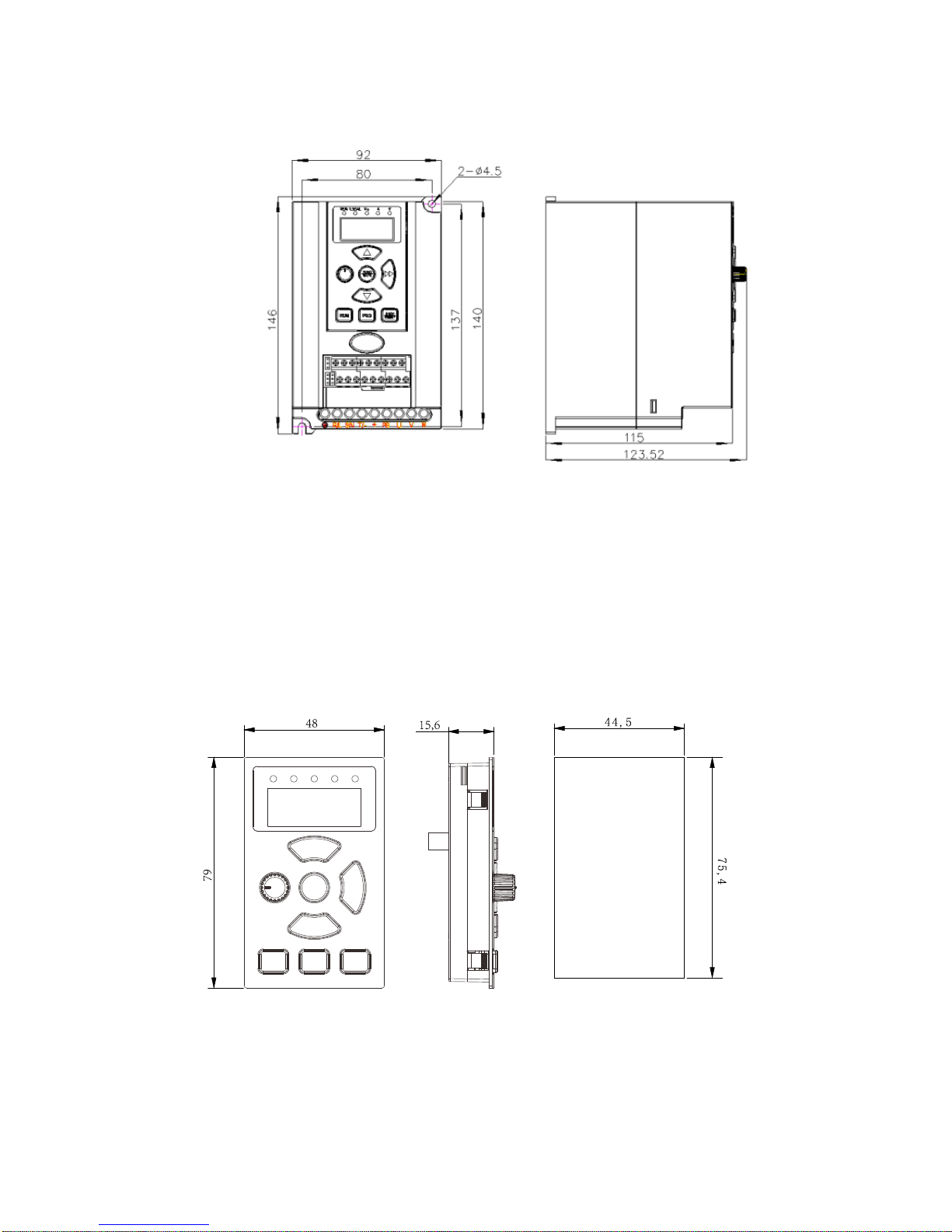
3.2.3 Demision............................................. 9
3.2.4 LED Keypad Display Unit Size............................ 9
4. Installation and Wiring ................................. 11
4.1 Installation................................................. 11
4.2 Wiring .................................................... 12
4.2.1 Overview............................................ 12
4.2.2 Power Terminals ...................................... 13
4.2.3 Control Circuit Wiring.................................. 13
5. Operation Procedures .................................. 20
5.1 Operation Guide ............................................ 20
5.1.1 LED Keypad ......................................... 20
5.1.2 Keypad Function Explanation............................ 20
5.1.3 Indicator Description................................... 21
5.1.4 Parameter Setting Method............................... 21
5.1.5 Motor parameters self-learning ........................... 22
5.1.6 Password setting ...................................... 23
6. Parameters ......................................... 24
6.1 Basic Parameters(F0)...................................... 24
6.2 Motor Parameter(F1)...................................... 27
6.3 Start/Brake Parameter(F2).................................. 28
6.4 Flux vector control parameters(F3)........................... 30
6.5 Current vector control parameter(F4).......................... 32
6.6 Multi-function terminal(F5)................................. 32
6.7 Output terminal control parameters(F6)........................ 38
6.8 Close-loop PID control(F7)................................. 43
6.9 MS parameters(F8)........................................ 45
6.10 Enhanced function(F9).................................... 45

3
6.11 Display Control Parameters(FA)............................ 48
6.12 Communication(FB)...................................... 50
6.13 Professional parameters(FC)............................... 51
6.14PLC parameters(FD)...................................... 51
6.15 Constant-pressure water supply (FE)............................ 54
6.16 Protection(FL).......................................... 54
6.17 Operation Time and Temperature of Cooling Fan (FN)........... 57
6.18 Protection of Parameters(FP)............................... 57
6.19 Factory Default(FU)...................................... 58
7. Troubleshooting ..................................... 59
8. Maintenance ........................................ 65
8.1 Routine Maintenance......................................... 65
8.2 Periodic Maintenance ........................................ 65
8.3 General Inspection::........................................ 66
8.4 Replacing Easily-worn Parts ................................... 66
8.5 Storing Inverters ............................................ 67
8.6 Warranty .................................................. 67
9. Parameter profiles ................................... 69
10. Communication Protocal.............................. 88
10.1 Communication Mode....................................... 88
10.2 Protocol Function .......................................... 88
10.3 Instruction ................................................ 93
10.4 The scaling rule of Inverter ................................... 94
Warranty Agreement ..................................... 96

4
1. Preface
Thank you for using HV950 series inverter made by HNC
HV950 series satisfies high performance requirements by using a unique control
method to achieve high torque, high accuracy and wide speed-adjusting range. Its
anti-tripping function and capabilities of adapting severe power network, temperature,
humidity, and dusty environment exceeds those of similar products made by other
companies, which improves the products reliability noticeably.
HV950considers customers’ needs and combines general purpose function and
industrial-oriented function. It features PI control, simple PLC, flexible I/O terminals
and pulse frequency setting. You can select whether to save the parameters upon
power off or stop, main and auxiliary frequency setting, etc. It is an integral,
cost-effective and highly reliable solution for manufacture in the related fields.
HV950 series can satisfy the customers’ requirements on low noise and EMI by
using optimized PWM technology and EMC design.
This manual provides information on installation, wiring, parameters setting,
trouble-shooting, and routine maintenance. In order to ensure the correct installation
and operation of the inverter, please read this manual carefully before using and keep
it in a safe place.

5
2. Inspection
Don’t install or use any inverter that is damaged or have fault parts otherwise
may cause injury.
Check the following items when unpacking the inverter.
1. Ensure there is operation manual and warranty cards in the packing box.
2. Inspect the entire exterior of inverter to ensure there are no scratches or
other damaged caused by transportation.
3. Check the nameplate and ensure it is what you ordered.
4. Ensure the optional parts are what you need if you have ordered any
optional parts.
Please contact the local agent if there is any damage in the inverter or the
optional parts.

6
3. Specifications and Optional Parts
3.1 Specifications
Table2-1 HV950 Specifications
Item
Description
Input
Rated voltage;
Frequency
HV950 G3:380V~440V;50Hz/60Hz
HV950 G1:200V~240V;50Hz/60Hz
Permissible
fluctuation
range
Voltage contant fluctuate ≤±10%, Transient fluctuate:
-15%~+10%, out of balance voltage rate: ≤3%,
frequency fluctuation:≤5%
Output
Rated voltage
HV950 G1:0~200V/240V
HV950 G3:0~380V/440V
Rated power
HV950 G1:0.40~2.2KW
HV950 G3:0.75~2.2KW
Frequency
0Hz~650Hz
Over load
ability
Heavy Duty:150%rated current for 1 minute,180%
rated current for 10s/1s(380V/220V series),200% rated
current for 1s;
Control
functions
Modulation
mode
Flux vector PWM modulation
Speed range
1:100
Starting torque
180% rated torque at 0.5Hz
Accuracy of
speed at steady
state
≤±0.5%rated synchronous speed
Torque boost
Auto torque boost,Manual torque boost
Acc/Dec curve
Linear
Jog
Jog frequency, Acc/Dec time,
Jog interval are adjustable
Multi-speed
operation
15 sections of frequency. Able to achieve through the
built-in PLC or terminals.
Closed-loop
control
Analog closed-loop
Auto voltage
regulation
Constant output voltage even if electric network voltage
fluctuates
Auto current
limiting
Operating current is limited automatically to avoid
frequent tripping of the inverter

7
Item
Description
Auto
carrier-wave
regulation
Adjust the carrier frequency automatically according to
the load characteristics;
Internal
counter
Counting the external pulse signal through X terminals
Methods of
inputting
commands
keypad panel, terminals and serial port
Methods of
setting up
frequency
Digital setting, AIand communication
Auxiliary
frequency
Flexible auxiliary frequency selectable
Analog output
terminals
0/4~20mA and 0/2~10V(selectable)
Protection function
Phase loss failure, Over/Under current, Over/Under
voltage protection, Overheat and overload protection
Environm
ent
Operating
environment
In-door,not subject to direct sunlight, no dust, corrosive,
flammable gas, oil mist, steam, water, or salt, etc
Altitude
Less than 1000m, derating is required more than 1000m
Ambient
temperature
-10℃~+40℃,derating is required from 40~50℃;
Increase every 1 above 40℃, derating 2%, highest
temperature allowed: 50℃
Humidity
Less than 95% RH,no condensing
Vibration
Less than5.9m/s2(0.6g)
Storage
temperature
-40℃~+70℃
Enclosure
Protection
level
IP20
Cooling
Fan cooling, natural cooling
Mounting mode
Mounted in a cabinet

8
3.2 Products Series Introduction
3.2.1 HV950 Models
HV950 G1/G3
Applicable motor power with power supply
:
HV950 G1
:
0
~
200V/240V
HV950 G3
:
0
~
380V/440V
Table2-2 Inverter series
Model
Rated capacity
(KVA)
Rated output
current(A)
Applicable motor
power(KW)
HV950-R40G1(B)
1.0
2.5
0.4
HV950-R75G1(B)
1.5
4.0
0.75
HV950-1R5G1(B)
3.0
7.5
1.5
HV950-2R2G1(B)
4.0
10.0
2.2
HV950-R75G3
1.5
2.3
0.75
HV950-1R5G3
3.0
3.7
1.5
HV950-2R2G3
4.0
5.0
2.2
3.2.2 Ordering information of HV950 series
Please refer to Figure2-1a and Figure 2-1b。
Figure2-1a
Table2-1a Explanations of inverter models
MODEL:HV950-R75G1(B)
POWER:0.75KW
INPUT:1PH AC 200~240V 8.2A 50/60HZ
OUTPUT:3PH AC 0~240 4.0A 50/60HZ
S/N:
HNC Electric Limited
Table2-1b HV950 series nameplate

9
3.2.3 Demision
Please refer to Figure 2-2
Figure2-2 HV950 series inverter size
Note: Net weight, 1.04KG
Gross weight (include user manual after package), 1.22KG
3.2.4 LED Keypad Display Unit Size
Through it, operation and configuration of the inverter can be done. Please refer to its
size and configuration in Figure 2-3.
Keypad dimensions Figure2-3 Keypad display unit
Gross weight (with package and manual) 1.22Kg

10
Model No.
L(mm)
W(mm)
H(mm)
Weight(Kg)
HV950-R40G1(B)
146
92
123.52
1.22
HV950-R75G1(B)
HV950-1R5G1(B)
HV950-2R2G1(B)
HV950-R75G3
HV950-1R5G3
HV950-2R2G3
3.2.5 Optional Parts
Table 2-3: recommended braking resistor
Model
Suggested value
of resistance
Suggested power
HV950-R75G3
250-350Ω
100W
HV950-1R5G3
200-300Ω
200W
HV950-2R2G3
100-250Ω
250W
HV950 series inverter (3phase product) is equipped with braking unit. If there
is a need for energy-consuming braking, please select a braking resistor in
Table2-3
The above Table 2-3 is a guide reference only, users can choose different braking
resistance and power according to each application.However, please be remembered
that the braking resistance shouldn’t be less than the above recommended value, but
the power is allowed to be exceed than the recommend numbers.Users need to select
the right braking resistors according to each application case,there are quite a few
aspects which will determine your choice of the resistors, such as the power of the
motor, system inertia,deceleration time, the energy of the load etc.The greater the
system inertia is, the shorter the required deceleration time is required,then the
braking frequency will be increased, which means you need to choose a bigger power
braking resistor with a lower braking resistance.
Note: the 220V single phase inverter has no brake unit buit in.

11
4. Installation and Wiring
4.1 Installation
1. Mount the inverter vertically indoors, with good ventilative conditions.
2.Ambient temperature should be within the range of-10℃~ 40℃. If the
temperature is higher than 40 ℃, the inverter should be derated and forced heat
dissipation is required.
3. Humidity should be lower than 90%,non-condensing;
4. Mount in the location free of direct sunlight, dust, metal powder, corrosive
gas or combustible gas;
5.Mount in the location where vibration is less than5.9m/s2(0.6g);
6. Dust-free, floating fiber and metal particles;
7. Install flat solid, no vibration;
8. Away from electromagnetic interference source.
Figure 4-1 Installation of the inverter
10kV
Power
trasformer÷
Motor
Metal
cabinet
AC input reactor
Metal cabinet
PLC
or
meters
Circuit breaker
Filter
AC output
reactor
>30cm
>50cm
Inverter
Motor cable
Control cables
>20cm
Power source
cable of inverter
Isolation
transformer÷
Power source
cable of meters

12
4.2 Wiring
4.2.1 Overview
You should finish the power circuit and control circuit wiring。
The figure below is the systematic wiring of the inverter
PB (-)
R
S
T
R
S
T
3-phase
380 V
50/ 60Hz M
U
V
W
PE
Auxiliary
power
Circuit
breake
DC current meter
0/4~20mA current
signal
AO
COM
GND
1TB
1TC
1TA Programmable relay output
RS485-
RS485+ Standard RS485
communication port
X1
X2
X3
X4
X5
Multi-function input 1
PLC
COM
Speed command
GND
+ 10 V
PE
0~10V/ 0 ~20 mA
Y1 Output 1: Open collector signal
P24
I
V
CN6
0/2 ~10V .
.
.
0/4 ~20mA
CN4
(+)
Power
circuit
Cont
rol
ciru
it
P24
ON
OFF
CN 5
.
.
.
.
.
.
Multi-function input 2
Multi-function input 3
Multi-function input 4
Multi-function input 5
AI
Figure 4-2Systematic Wiring Diagram
Table 4-1 Recommended MCCB Capacity and Copper Cable Section Area
Model
MCCB
Circuit
breaker
(A)
Power circuit(mm2)
Control
cable
(mm2)
Input
cable
Braki
ng
line
Outpu
t cable
Earth
cable
HV950-R40G1(B)
16
1.5
1.0
1.0
2.5
1.0
HV950-R75G1(B)
20
2.5
1.0
1.0
2.5
1.0
HV950-1R5G1(B)
32
4.0
1.5
2.5
4.0
1.0
HV950-2R2G1(B)
50
6.0
1.5
2.5
6.0
1.0
HV950-R75G3
10
1.0
1.0
1.0
2.5
1.0
HV950-1R5G3
16
1.5
1.0
1.5
2.5
1.0
HV950-2R2G3
16
1.5
1.5
1.5
2.5
1.0

13
4.2.2 Power Terminals
1.Definitions of power terminals
T/-
R/L VU W
+
S/N PB
Table 4-2Definitions of power terminals
Terminal name
Description
R、S、T
/L、N
3-phase AC input /
1-phase AC input
(+)、PB
External braking resistor
(+)、(-)
DC positive, negative bus input
U、V、W
3-phase AC outputs
Protective earth
4.2.3 Control Circuit Wiring
Control Terminals and Jumpers
The terminal row and jumpers on control panel is CN4, CN5, CN6
Control terminals functions are listed in Table 3-4,Jumper’s functions in 3-5. Be sure
to set the jumper and wire the terminals properly. It is recommended to use cable of
section area bigger than 1mm2.
Table 4-3 Function of control terminals
Mark
Function
CN8- CN10
Analog I/O, digital I/O, relay outputs
Table 4-4 Jumpers’ function
Mark
Function&Setting
Default
CN4
CCI current/voltage input selection
I:0~20mA current signal
V:0~10V voltage signal
0~10V
CN5
485 terminal resistor selection:
ON: 120Ω terminal resistor
OFF: No terminal resistor.
No
resistor
CN6
AO current/voltage input selection
0/4~20mA: AO current signal
0/2~10V: AO voltage signal
0~10V

14
Terminal strip layout
The layout is shown below:
Y1
X1 X4
P24
PLC+10V
X5
GND X2 X3
COM
485+ 485-
AO AI TC TB TA
TA-TB:Normally closed;TA-TC:Normally open
Table 4-5 Terminal function table
Category
Terminals
Name
Function
Specification
Communication
485+
RS485com
munication
port
RS485+(differential signal)
Standard RS-485
communication
port,
Please use
twisted-pair cable
or shielded cable
485-
RS485-(differential signal)
Analog input
AI
Analog
input
Accepting analog voltage/current
input.CN4 can select voltage or
current input mode,Voltage
input mode is the default
(Reference ground:GND)
Input voltage
range:0~10V
(input
resistance:100kΩ)
Input current
range:0~20mA
(input
resistance:500Ω)
resolution:1/2000
Analog output
AO
Analog
output
Be able to output analog
voltage/current, Jumper CN6 can
select voltage or current input
mode. Voltage input mode is the
default mode. Refer to F6.04 for
details (reference ground: GND)
Output current
range: 0/4~20mA
Output voltage
range: 0/2~10V
Digital input
X1~X5
Multi-funct
ional
digital
inputs 1~5
Can be defined as
multi-functional digital inputs,
see Section 7.6
Reference ground: COM
Optical-isolator
2-way input
input resistance:
2kΩ
maximum input
frequency: 200Hz
Input voltage
range: 9~30V
PLC
Common
terminal
Common terminal for
multi-functional inputs
P24
+24V
supply
Providing +24V power supply
Output:+24V,set
point accuracy:
±10%
Max output
current:200mA
COM
+24V
common
terminal
Isolated internally with GND
Isolated internally
with GND

15
Category
Terminals
Name
Function
Specification
Digital input
Y1
Open
collector
output 1
Programmable terminals,
defined as multi-function digital
outputs, see Section 7.7.
Optical-isolator
output:
24VDC/50mA
Power supply
+10V
+10V
power
supply
Provide +10V power supply
Output: +10V,
Setpoint accuracy:
±10%
Max. output
current: 100mA
GND
GND of
+10V
power
supply
reference ground of analog
signal and 10V power supply
Isolated internally
with COM
Others
TA/TB/T
C
Relay
output
TA, TB and TC can be defined
as multi-functional digital output
signals. please refer to Section
7.7
TA-TB:normally
closed;TA-TC:
normally open
Contact capacity:
250Vac/2A
(COSφ=1),
250Vac/1A
(COSφ=0.4),30
Vdc /1A
The PLC terminal can sink or source current. Wire connections X1~X5is flexible
and the typical wiring is shown below:
①Connection method 1
It is default to use the inverter’s internal power source 24V, i.e. PLC connected
with P24.
If you want to use external power supply, make sure to remove the wire between
PLC and P24.

16
Figure 4-3 External power supply wiring diagram
②Connection Method 2
Inverter’s internal +24V power supply is used and the external controller
uses PNP transistors whose common emitters are connected, as shown in
Figure 3-14.
Figure 4-4 Internal +24V wiring diagram (source)
Inverter’s internal +24V power supply is used and the external controller uses
PNP transistors whose common emitters are connected.(Remote the wire
between PLC and P24).
COM
●
HV950
P
E
●
PLC
Xi
●
●
●
P
24
COM
●
●
24
V DC
D
2
+
-
3
.
3
V
●
X
5
●
3
.
3
V
External controller
Current
+
24
V
X
1
、
X
2
. . .
X
5
,
PLC
HV950
+
3
.
3
V
COM
P
24
R
DC
+
-
K
+
-
Shield near the inverter
should be grounded

17
Figure 4-5 Internal +24V wiring diagram (drain)
When using External power supply, remember to disconnectPLC and P24
Figure 4-6 External power supply wiring (source)
●
●
●
●
●
●
●
●
●
9
~
30
V
+
-
HV950
P
E
PLC
Xi
P
24
COM
24
V DC
D
2
+
-
3
.
3
V
X
5
3
.
3
V
External controller
●
●
●
●
●
●
●
●
●
●
HV950
P
E
PLC
Xi
P
24
COM
24
V DC
D
2
+
-
3
.
3
V
X
5
3
.
3
V
External controller
Shield bear the inverter
should be grounded
Shield near the inverter
should be grounded

18
External power supply wiring (drain)(Remember to disconnect PLC and P24)
Figure 4-7 External power supply wiring (drain)
5)Multi-function Output Terminal Wiring
①Terminal Y1 can use the internal 24V power supply, see the figure below:
Figure 4-8 Multi-function output terminal wiring1
①Terminal Y1 can also use external power (9~30V) supply:
HV950
P
24
+
5
V
+
24
V
COM
Y
1
Relay
●
●
●
●
●
●
●
●
●
●
+
-
9
~
30
V
HV950
P
E
PLC
Xi
P
24
COM
24
V
DC
D
2
+
-
3
.
3
V
X
5
3
.
3
V
External controller
Shield grounded near
the inverter

19
Figure 4-9 Multi-function output terminal wiring2
Note:
Don’t short terminals P24 and COM, otherwise the control board may be
damaged。
DC
9
~
30
V
HV950
COM
Y
1
P
24
+
5
V
+
24
V
+
-
Relay

20
5. Operation Procedures
5.1 Operation Guide
5.1.1 LED Keypad
LED keypad display unit is to receive command and display parameters.
Keypad diagram
5.1.2 Keypad Function Explanation
Keys on the LED keypad display unit refer to the function of each key in Table 6-1.
Table 6-1 Key’s function
Key
Name
Function
PRG
Program/Esc key
To shift between program state and Esc
state
FUNC/DATA
Function/Data
key
To shift between function code menus,
confirm modification
▲
Increase key
To increase data or function code number
▼
Decrease key
To decrease data or function code number
Shift key
To scroll over the displayed parameters,
such as voltage、frequency. To select the
digit to be modified
RUN
Run key
In the keypad operating mode, press the key
to start running
STOP/RESET
Stop/Reset key
In keypad mode, stop the inverter or reset in
case of alarm or fault;
This manual suits for next models
6
Table of contents
Other HNC Electric DC Drive manuals
Popular DC Drive manuals by other brands

DR. BENDER
DR. BENDER SXM-V operating manual

Arroyo Instruments
Arroyo Instruments LaserSource 4400 Series user manual

LOVATO ELECTRIC
LOVATO ELECTRIC VLB3 Series quick guide

Rowan Elettronica
Rowan Elettronica 380S instruction manual

YASKAWA
YASKAWA SGM series user manual

THOMSON
THOMSON Omnidrive Series installation manual