manuals.online logo
Brands
  1. Home
  2. •
  3. Brands
  4. •
  5. WEG
  6. •
  7. DC Drive
  8. •
  9. WEG DeviceNet CFW500 User manual

WEG DeviceNet CFW500 User manual

Document: 10003219660 / 00
The values shown are subject to change without prior notice.
WEG Drives & Controls - Automação LTDA.
Jaraguá do Sul - SC - Brazil
Phone 55 (47) 3276-4000 - Fax 55 (47) 3276-4020
São Paulo - SP - Brazil
Phone 55 (11) 5053-2300 - Fax 55 (11) 5052-4212
POWER CONNECTIONS
For further details, refer to user's guide chapter 3.
PE PE WVU
RBR
ST U
-Ud +Ud VW
PE PE
(*)
Shielding
R
S
T
Input power
supply
Disconnecting
switch Fuses
(*) The power terminals -Ud, BR and +Ud are not available in models of frame A.
(a) Frame A, B and C
Shielding
PE
Disconnecting
switch Fuses
R
S
T
Input power
supply
PE WV U
RBR DCR
ST U
-Ud +Ud VW
PE PE
(b) Frame D
Frequency Inverter
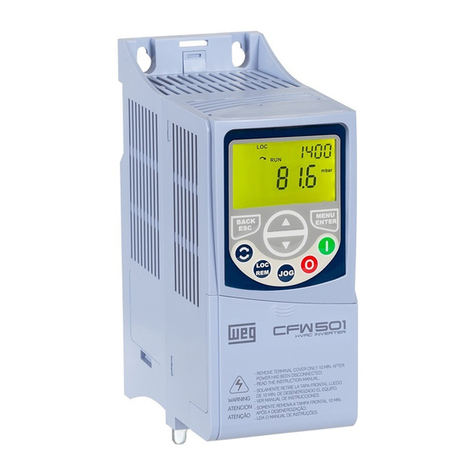
CFW500
Quick Setup Guide
DANGER!
Always disconnect the main power supply before touching any
electrical component associated to the inverter. Several
components can remain charged with high voltages or remain
in movement (fans) even after the AC power is disconnected or
switched off.
Wait at least ten minutes after turning off the input power for the
complete discharge of the power capacitors.
Always connect the grounding point of the inverter to the
protection earth (PE).
Motors I Automation I Energy I Transmission & Distribution I Coatings
Phone: 800.894.0412 - Fax: 888.723.4773 - Web: www.clrwtr.com - Email: [email protected]
Oriented Start Up - STARTUP Group (Scalar - V/f Mode)
Prog DEF User Description
P0202 0 0 Control Type V/f.
P0401 - Motor Current (A).
P0402 1710 Motor Speed (rpm).
P0403 60 Motor Frequency (Hz).
Note: set P0202 = 5 during oriented start-up for improved speed control and higher torque capacity at low speed
(especially < 5 Hz).
 Set as per motor nameplate data.
Motor Overload Settings - MOTOR Group
Prog User Description
P0156 1.1 x P0401 Overload Current at 100% Speed.
P0157 1.0 x P0401 Overload Current at 50% Speed.
P0158 0.8 x P0401 Overload Current at 5% Speed.
Basic Application - BASIC Group
Prog DEF Description
P0100 10.0 s Acceleration Time (s).
P0101 10.0 s Deceleration Time (s).
P0133 3.0 Hz Minimum Speed (Hz).
P0134 66.0 Hz (55.0) Hz Maximum Speed (Hz).
PROGRAMMING
CFW500 Keypad
Menu/Enter button:
Enter programming mode.
Use to Select/Save.
Run button:
Run in local mode.
Stop button:
Stop in local mode.
Reset.
Up/Down buttons:
Adjust speed in local
mode.
Navigate through
parameters.
Back/ESC button:
Return to monitoring
mode.
Return to previous
programming level.
Relay Output
Prog DEF User Description
P0275 13 11 Run.
12 Ready.
13 No Fault.
14 With Fault.
11 DO1-RL-NO Normally open. NO
NC
Top connection.
13 DO1-RL-C Common.
15 DO1-RL-NC Normally closed.
Note: for more advance functions, please refer to the the programming manual.
Changing Monitor Display Parameter
Secondary
display
P0206
Main display
P0205
Prog DEF User Description
P0205
P0206
2
1
1 Speed Reference (rpm).
2 Output Speed (rpm).
3 Motor Current (A).
5 Output Frequency (Hz).
7 Output Voltage (V).
9 Motor Torque (%).
Note: for more advance functions, please refer to the programming manual (chapter 5.3).
Loading Factory Default Setting
Prog DEF User Description
P0204 0 5 Load WEG 60 Hz.
6 Load WEG 50 Hz.
TYPICAL CONTROL CONNECTION
Example 1: 2 - Wire Start/Stop, Speed Potentiometer
DIP switch 1
VAI1 mA
ON
ON
Start/Stop
FWD/REV
Speed
potentiometer

1 DI1 Digital input 1.
Top connection.
CFW500-IOS (standard).
3 DI2 Digital input 2.
5 DI3 Digital input 3.
7 DI4 Digital input 4.
9 +24 Vdc 24 V dc power supply (150 mA).
2 AO1 Analog output 1.
Bottom
connection.
4 GND Reference 0 V.
6 AI1 Analog input 1.
8 +10 Vdc Reference + 10 Vdc potentiometer.
OFF
OFF
CFW500 - IOS
Note: (*) The digital input 2 (DI2) can also be used as input in frequency (FI). For further details refer to the programming
manual of the CFW500.
Prog DEF User Description
P0220 2 1 Local/Remote = Always Remote.
P0222 1 1 Remote Reference = Al1.
P0226 4 4 FWD/REV = DIx.
P0227 1 1 Run/Stop Remote = DIx.
P0231 0 0 AI1 = Speed Reference.
P0233 0 0 AI1 = 0 to 10 V.
P0263 1 1 DI1 = Run/Stop.
P0264 8 8 DI2 = Clockwise Rotation Direction.
Example 2: 3 - Wire Start/Stop, 4 to 20 mA Reference
DIP switch 1
VAI1 mA
Start
Stop
4 to 20 mA
reference

1 DI1 Digital input 1.
Top connection.
CFW500-IOS (standard).
3 DI2 Digital input 2.
5 DI3 Digital input 3.
7 DI4 Digital input 4.
9 +24 Vdc 24 Vdc power supply (150 mA).
2 AO1 Analog output 1.
Bottom
connection.
4 GND Reference 0 V.
6 AI1 Analog input 1.
8 +10 Vdc Reference + 10 Vdc potentiometer.
CFW500 - IOS
Prog DEF User Description
P0220 2 1 Local/Remote = Always Remote.
P0222 1 1 Remote Reference = Al1.
P0227 1 1 Run/Stop Remote = DIx.
P0231 0 0 AI1 = Speed Reference.
P0233 0 1 AI1 = 4 to 20 mA.
P0263 1 6 DI1 = Start.
P0264 8 7 DI2 = Stop.
Example 3: 2 - Wire Start/Stop, Multispeed (4 Speeds)
ON
ON
ON
OFF
Start/Stop
Speed
DIP switches
(not applicable)
Speed
OFF
OFF


1 DI1 Digital input 1.
Top connection.
CFW500-IOS (standard).
3 DI2 Digital input 2.
5 DI3 Digital input 3.
7 DI4 Digital input 4.
9 +24 Vdc 24 Vdc power supply (150 mA).
2 AO1 Analog output 1.
Bottom
connection.
4 GND Reference 0 V.
6 AI1 Analog input 1.
8 +10 Vdc Reference + 10 Vdc potentiometer.
Prog DEF User Description
P0220 2 1 Local/Remote = Always Remote.
P0222 1 8 Remote Reference = Multispeed.
P0227 1 1 Run/Stop Remote = DIx.
P0263 1 1 DI1 = Run/Stop.
P0265 20 13 DI3 = Multispeed.
P0266 10 13 DI4 = Multispeed.
P0124 3.0 Speed =  (DI3 = Open and DI4 = Open).
P0125 10.0 Speed =  (DI3 = Open and DI4 = Closed).
P0126 20.0 Speed =  (DI3 = Closed and DI4 = Open).
P0127 30.0 Speed =  (DI3 = Closed and DI4 = Closed).
Note:  Speed setting depends on application.
Phone: 800.894.0412 - Fax: 888.723.4773 - Web: www.clrwtr.com - Email: [email protected]

Other manuals for DeviceNet CFW500

12

Other WEG DC Drive manuals

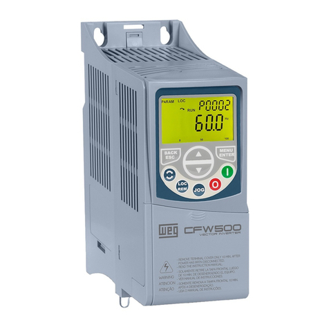
WEG CFW-11 Series Owner's manual

WEG

WEG CFW-11 Series Owner's manual

WEG CFW-11W Installation and operating instructions

WEG

WEG CFW-11W Installation and operating instructions

WEG MW500 series User manual

WEG

WEG MW500 series User manual

WEG DeviceNet CFW500 User manual

WEG

WEG DeviceNet CFW500 User manual

WEG SCA06 User manual

WEG

WEG SCA06 User manual

WEG CFW-11 Series User manual

WEG

WEG CFW-11 Series User manual

WEG Easy Drive CFW10 User manual

WEG

WEG Easy Drive CFW10 User manual

WEG CFW300-KHMIR Quick guide

WEG

WEG CFW300-KHMIR Quick guide

WEG CFW100 series User manual

WEG

WEG CFW100 series User manual

WEG CFW900 User manual

WEG

WEG CFW900 User manual

WEG CFW-11 Series Operating instructions

WEG

WEG CFW-11 Series Operating instructions

WEG CFW-11 Series Owner's manual

WEG

WEG CFW-11 Series Owner's manual

WEG CFW900 User manual

WEG

WEG CFW900 User manual

WEG DeviceNet CFW500 User manual

WEG

WEG DeviceNet CFW500 User manual

WEG DeviceNet CFW500 Instructions for use

WEG

WEG DeviceNet CFW500 Instructions for use

WEG CFW700 Operating instructions

WEG

WEG CFW700 Operating instructions

WEG MVW3000 Series User manual

WEG

WEG MVW3000 Series User manual

WEG CFW501 User manual

WEG

WEG CFW501 User manual

WEG CFW-11 Series Owner's manual

WEG

WEG CFW-11 Series Owner's manual

WEG CFW700 User manual

WEG

WEG CFW700 User manual

WEG CFW-11 Series User manual

WEG

WEG CFW-11 Series User manual

WEG CFW100 series Owner's manual

WEG

WEG CFW100 series Owner's manual

WEG CFW-10 EASYDRIVE User manual

WEG

WEG CFW-10 EASYDRIVE User manual

WEG CFW100 series User manual

WEG

WEG CFW100 series User manual

Popular DC Drive manuals by other brands

Raymarine IO Drive installation guide

Raymarine

Raymarine IO Drive installation guide

Anaheim Automation DPE25601 user guide

Anaheim Automation

Anaheim Automation DPE25601 user guide

Danfoss VLT BACnet/IP MCA 125 installation guide

Danfoss

Danfoss VLT BACnet/IP MCA 125 installation guide

Becker P5/16R+ operating instructions

Becker

Becker P5/16R+ operating instructions

SOMFY Sunilus io installation guide

SOMFY

SOMFY Sunilus io installation guide

Rockwell Automation Allen-Bradley PowerFlex 755TS Series Hardware service

Rockwell Automation

Rockwell Automation Allen-Bradley PowerFlex 755TS Series Hardware service

YASKAWA CR700 Technical manual

YASKAWA

YASKAWA CR700 Technical manual

Danfoss VLT HVAC Drive FC 102 operating instructions

Danfoss

Danfoss VLT HVAC Drive FC 102 operating instructions

Masterflex P/S 850-3010 operating manual

Masterflex

Masterflex P/S 850-3010 operating manual

Aumuller KS15 Assembly instruction

Aumuller

Aumuller KS15 Assembly instruction

TECO JSDE Series manual

TECO

TECO JSDE Series manual

Parker Compax3H C3H1xxV4 Series installation manual

Parker

Parker Compax3H C3H1xxV4 Series installation manual

Danfoss FC 300 Interbus operating instructions

Danfoss

Danfoss FC 300 Interbus operating instructions

Intelligent Motion Systems Excellence in Motion IM805H operating instructions

Intelligent Motion Systems

Intelligent Motion Systems Excellence in Motion IM805H operating instructions

Johnson Controls PENN VFD68 installation instructions

Johnson Controls

Johnson Controls PENN VFD68 installation instructions

Dorner 2200 series Installation, maintenance & parts manual

Dorner

Dorner 2200 series Installation, maintenance & parts manual

Geckodrive G203V Installation notes

Geckodrive

Geckodrive G203V Installation notes

American Control Electronics PAT Series user manual

American Control Electronics

American Control Electronics PAT Series user manual

manuals.online logo
manuals.online logoBrands
  • About & Mission
  • Contact us
  • Privacy Policy
  • Terms and Conditions

Copyright 2025 Manuals.Online. All Rights Reserved.