Hobbies & Helis Quick 30 Pro Datasheet

Exclusively Distributed by:
Hobbies & Helis International
201 south 3rd. st. & 309 north
Coopersburg, PA 18036
Phone: (610)-282-4811 Fax: (610)-282-4816
Website: http://www.hhiheli.com http://www.QuickHeli.com
Assembly Instructions & Parts Listing

Quick 30 Pre-Assembly Information
Quick Worldwide & Hobbies & Helis International:
Quick of Japan and Hobbies & Helis International teamed up to make
parts 6 years ago. In the beginning, our specialty was the manufacturing
of various upgrade parts for many of the plastic helicopters on the market.
After four years of distributing numerous upgrades and crash parts for other
helicopters, we decided to develop our own line of helicopters. That's when
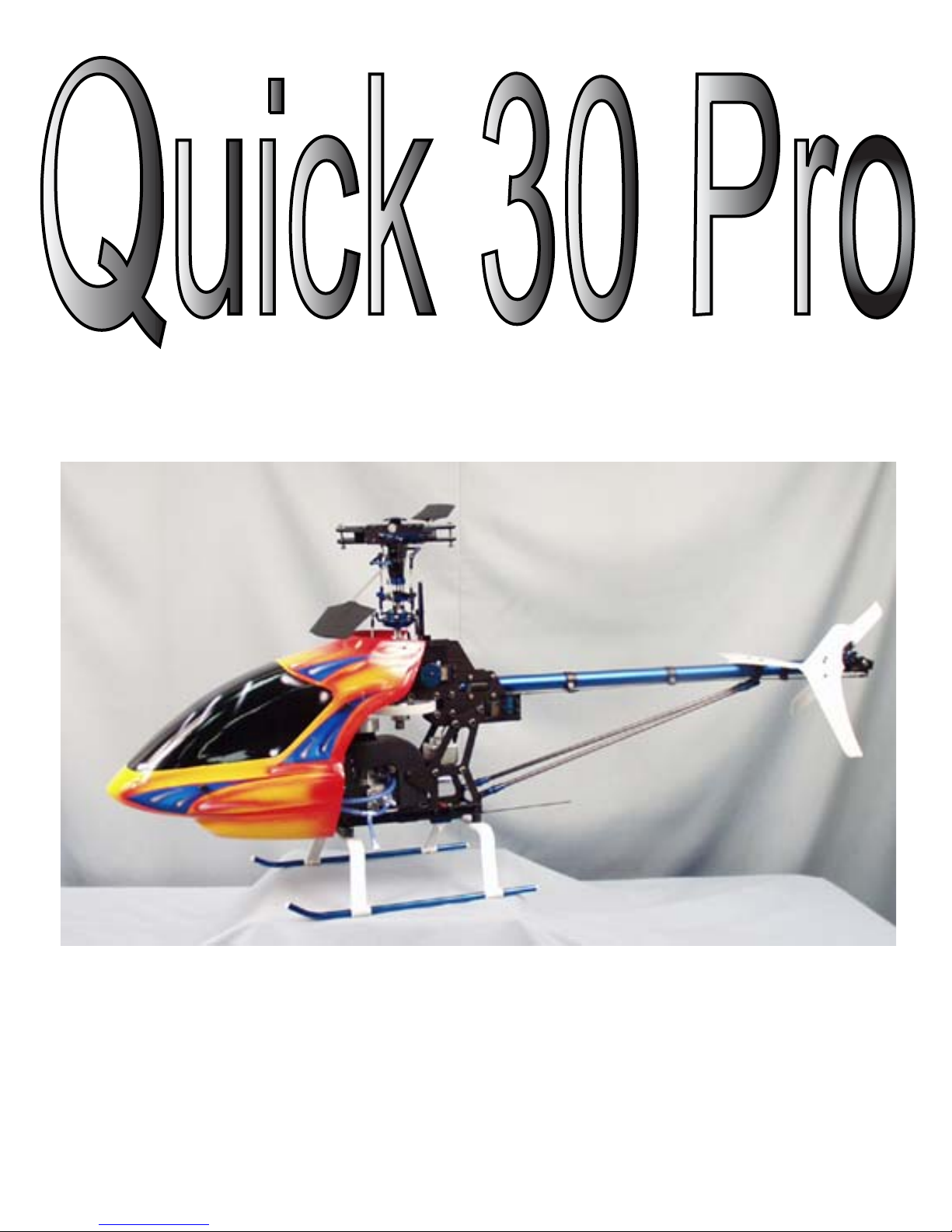
the notion of the Quick 30 Pro was conceived. As the development of the
kit began, initial designs were approved, proto-types were made and
flown - all to ensure that the design was flawless. No minor details were
over-looked. After countless hours of hard work and dedication,
Hobbies & Helis is proud to release the first in a new standard in
Helicopters - the Quick 30 Pro.
Warning:
The radio-controlled model helicopter contained in this kit is not a toy.
Rather, it is a sophisticated piece of equipment. This product is not
recommended for use by children. Radio controlled models such as this
are capable of causing both property damage and/or bodily harm to both
the operator/assembler and/or spectator if not properly assembled and
operated. Hobbies & Helis assumes no liability for damage that could
occur from the assembly and/or use/misuse of this product.
AMA:
We strongly encourage all prospective and current R/C aircraft pilots to
join the Academy of Model Aeronautics. The AMA is a non-profit
organization that provides services to model aircraft pilots. As an AMA
member, you will receive a monthly magazine entitled Model
Aviation, as well as a liability insurance plan to cover against possible
accident or injury. All AMA charter aircraft clubs require individuals to
hold a current AMA sporting license prior to the operation of their model.
Pre-Assembly Information:
Quick Helicopters are put together with care and quality topping our
priority list. A recommendation when you are ready to begin building this
model is that you examine the kit and understand the contents of the
packages and read thoroughly before starting the assembly process.

Manual Index
Quick 30 Pre-Assembly Information............................. 2
Manual Index.........................................................................3
Quick 30 Features...............................................................4
Tools Needed.........................................................................5
Additional Parts Needed......................................................6
Optional Parts and Accessories.........................................7
Radio Requirements...............................................................8
Hardware Identification.........................................................9
Upper Frame Assembly......................................................10
Elevator Control....................................................................11
Install of Front Lowers Frames......................................12
Radio Bed & Gyro plate.................................................13
Tail Pulley & Main Gear................................................14
Clutch Lining & Clutch Bell..........................................15
Fan Cover, Motor Mount, & Fan Hub.......................16
Clutch, Motor, & Frame Rails........................................17
Servo Installation...................................................................18
Fuel Tank & Landing Gear.............................................19
Tail Case................................................................................20
Tail Boom & Boom Supports.........................................21
Tail Fins & Swashplate & Anti-Rotate Guide...........22

1. Heavy Duty Frame Construction: Quick 30 frames are made of the highest Quality
2000 series Aluminum. These frames are not only rigid but will provide excellent
vibration absorption.
2. One-Way Hex Start Shaft System: The one-way bearing allows the engine to
continue to run after the starter motor has been stopped.
3. Ball Bearing Idler Pulley: The ball bearing idler pulley provides smooth consistent
power to the tail by not allowing the belt to jump teeth.
4. Belt driven Tail: Belt Driven tail is not only a reliable way to drive a tail, but is also
very smooth and is low maintenance feature.
5. High Quality Ball Bearings: Quick 30 Pro offers ball bearings on all moving parts
unlike other machines.
6. EMS Collective System: The EMS Collective design allows ease of setup with fewer
moving parts. EMS constitutes overall design simplicty and represents the future of
helicopter technology.
7. Heavy-Duty Clutch System: Based on the same design as our famous heavy-duty
clutch upgrade that fits most popular machines, this clutch will give many years of
problem free operation.
8. Control Linkages: The control linkages that are provided with the Quick 30 Kit are
high quality 2.3mm stainless steel rods and the rod ends are made of a high quality
liquid Delrin.
9. Independent Blade Axle Design: The dual blade axle construction is pinned
above and below the centerline of the of the main blade grips. This rotor head design
far exceeds the quality of any rotor head on the market today.
10. Advanced Airfoil Flybar Paddles: These paddles will provide the best both kind of
flight characteristics 3D & Sport flying. Not only do they provide smooth forward flight,
they also provide quick response upon demand.
11. Rearward facing Engine Design: This design provides easy access to the glow
plug and is adventageous for easy engine removal.
12. This machine utilizes high quality, Machined parts which are also bright-dipped and
anodized for metal protection and beautiful appearance.
Quick 30 Features

Tools Needed to Assemble the Quick 30 Pro
Phillips Screw Driver Hobby Knife
EXL16030-1 $0.99
Metric Ruler
Scissors Nut Drivers
5.0mm WIH26550 $7.50
5.5mm WIH26555 $7.70
7.0mm. WIH26570 $7.90
Allen Drivers
1.5mm WIH26315 $4.10
2.0mm WIH26320 $3.80
2.5mm WIH26325 $3.80
3.0mm WIH26330 $3.90
Needle Nose Pliers
Piston Head Lock
HHI7020 $6.99
Carbon Paddle Gauges
HHI7000 $9.99
Pitch Gauge
HHI7001 $24.99
Bubble Blade Balancer
HHI7010 $39.99
High Point Balancer
DUB499 $29.99
Counter Balance Shaft
HHI7030 $18.99
Ball link Pliers
Mat1001 $39.99
Ball End Drivers
HHI7050 $14.99
Universal Flybar Lock
HHI7040 $24.99

Motor Requirements (Not Included)
Buliding Supplies (Essential)
Any .30 class motor
OS30 OSMG1940 $119.99
Glow Plug
OSMG2691 $6.25
Fuel Filter
QUI9002 $4.99
30 Size Muffler
HHI3004 $44.99
Spiral Wrap
HHI2809 $2.49
HHI2810 $2.49
CA Glue
GBG1 $6.29
Fuel Tubing
PRA7092 $2.49
JB Weld
JBW8265S $6.29
4" Small Wire Ties
HHIWT01 $2.49
Locktite
PT42
$2.99

Option Parts & Accessories
Receiver Wrap
HHI2008 $3.49
Receiver Hold Down Straps
HHI55** $4.99
2 Per Bag & Colors: Red,White,Purple,Black
Receiver Strong Box
HHI2200 $12.99
Mini Cock Striaght
TET4311 $15.99
Triangle Joint
TET4302 $8.99
Tube Ends
QUI9001 $3.99
Base Load Antenna
HHI5302 $19.99
Finishing Caps 20 Per Bag
HHIM1110* $1 1.99
Available in Purple,Gold,Clear
Anodizing
Quick 30 Pro Servo Arm Set
Call or E-mail $24.99
30 Size Skid Stops
HHI200* $6.99
Available in many Colors
See website or Call for Detail
Landing Gear Damp.
HHI2004 $14.99
Flybar Stiffeners
HHI4023 $16.99
Throttle Extension (OS)
HHI2550B $1 1.99

Radio Requirements
Radios:
Hobbies & Helis & it's distributors carry
various lines of helicopter radios. We
recommend the use of at least a 7 or 8
channel radio. Other radios support the EMS
Mixing but provide less of the essentail
functions that make flying more enjoyable. In
conclusion, any radio that supports EMS
mixing will work fine.
Servos:
This is the single most important function of
the helicopter. Any premium sport servo will
offer acceptable perfomance. However due
to the nature of EMS collective we suggest
the use of digital servos to enhance and
ensure match servo timing without servo
interaction.
Field Equipment
Hand Crank Pump
IMP66710 $27.99
Glow plug leads
HCAP2501 $6.99
or make your own.
Super-X Pump &
Switch SOTP1750
$29.95
Quick Field Charger
HCAM3000 $59.99
Power Panel
HCAP0305 $34.99
12V 15A Starter Battery
HCAP3305 $18.99
Torque Master 180
HCAP3305 $69.99
Standard Glow Starter
GPMP2022 $34.99
Field Box
HHI7500 $39.99

Hardware Identification
Note: Print this page and keep near by during the building process for the identification of all the hardware.
The drawings on this page are scaled so that you may hold the part to the picture for sizing.
Nuts & Lock Nuts
From Left to Right.
2.6mm Nut, 2.6mm Locknut, 3mm Nut, &
3mm Locknut
2.6mm Cap Head Bolts
2.6 X 10mm
2.6 X 6mm
3mm Cap Head Bolts
3 X 35mm
3 X 25mm
3 X 18mm
3 X 16mm
3 X 15mm
3 X 12mm
3 X 10mm
3 X 8mm
3 X 6mm
Set Screws
From left to right the sizes are:
3mm, 4mm
Washers
Nord Lock
Washers
3mm
Washers
2mm Phillips
Head Screws
Screws
Self-Tap
Screws
Other Hardware
Pivot Ball
3 X 4mm
Standard
Shim Ball

Step 1: Upper Frame & Bearing Block Assembly
Read the entire manual first to get an idea of the machine's makeup, each step will
contain a parts list, a text description of the assembly, and pictures to illustrate the
construction. If there are any questions or concerns call or E-mail us and will be happy
help. Also, if possible, print this manual in color because we have some things color-coded.
It is also recommended that you degrease your bolts with acetone or rubbing alcohol and use
blue (242) locktite. The alcohol/acetone helps the locktite stick.
Main Shaft
Bearing Blocks (2)
Clutch Bell
Bearing Block (1)
Counter Gear
Assm. &
BRG. Block (1)
Parts List
5 X 10 X 4mm
Bearings Flanged (2)
3 X 8mm
Cap Head Bolts (20)
Upper Frames (2)
1 - Locate both upper frames install the 5 X 10 X 4mm Bearings
with flanged portion of the bearing facing toward inside
(Hole ID Yellow).
2 - It is necessary that the ridge portion of the Main shaft bearing
blocks face each other on all installation. The ridge is identified
as the side which only a portion of the bearing can be viewed.
3 - Begin installing the main shaft bearing blocks on half of the
frame (RED). Next Install the Clutch bell bearing block with the
smaller inside hole facing up (BLUE). Now install the Counter
gear Assm. w/Brg. block. (GREEN)
Note: If Bearings are a tight fit, use round file or fine sand paper rolled in to a tube
and lightly sand until proper fit is acquired.

Step 2: Elevator Control Shaft
Parts List
Inner Elevator
Control Arm (1)
Outer Elevator
Control Arm (1)
Elevator Control
Shaft (1)
3mm Set Screws (2)
The Inner Elevator Control
Shaft is attached to the
Elevator Control Shaft using
3mm Set Screw being sure
that the set set screw hits
the flat on the shaft. Then
insert the shaft through the
bearing in the frame. Now
attach the Outer Elevator
Control Arm using the
same method as Inner
Elevator Control Arm. Note:
The Inner Elevator Control
Arm has bigger hole where
the shaft is inserted.
Step 2-2: Main Frame Support
Front Frame Support
3 X 8mm Cap Head Bolts (4)
Parts List
Install the Frame Support to one side of the frames
using (2) 3 X 8mm Cap Head Bolts the other 2 bolts
will be used when the other side of the frames are
captured.
After you complete attaching the f
rame support
attach the other side of the upper frames.

Step 2-3: Install of Front Lower Frames
Parts List
Lower Front Frames
3 X 8mm Cap Head Bolts (4)
Attach the Lower Frames
to the Frame Support
using 3 X 8mm Cap
Head Bolts. By
Examining the Frame
Piece, you will notice
that there are 3 holes for
attaching to the Frames
to the Frame Support.Use
only the top two holes
(Marked in RED) at this point, as the last hole will be used
for the right-angle frame pieces to be installed later.
Step 2-4: Install of Rear Lower Frames
Parts List
Lower Rear Frames (2)
Cross-Spacer 12mm (6)
Cross-Member 26mm (3)
3 X 22 mm Cap Head Bolts (6)
Loctite the 3 X 22mm Bolt and place it through the
hole (Marked in RED) in the Lower frame piece.
Place the 12mm Cross-spacer on the other side.
Place a 26mm Cross-member between the frames
behind the corresponding hole. Attach the frame
piece and finish installing the remaining bolts and
cross-members in the same manner. Note: Repeat
process on other side

Step 3: Install front Radio Bed & Gyro Plate
Parts List
Front Radio Bed (1)
Rear Gyro Mount (1)
3 X 6mm Cap Head Bolts (10)
1. Install front Radio Tray and Rear Gyro Mount using 3 X 6mm Cap
head bolts. The Red Dot indicate the holes. Remember to put the bolts in
both sides of the frames.
Step 4: Main Gear & Auto-Rotation Clutch
Parts List
Main Gear (1)
Auto-Rotation Clutch (1)
3 X 6mm Cap Head Bolts (4)
Install the Main Gear to the Autorotation clutch
using 3X6mm Cap Head bolts. The main
gear is to be bolted to the recessed flat
portion of the auto-rotation clutch. As
shown below.
Bottom View
Top View

Step 5: Installation of Front Tail Pulley
Parts List
Tail Pulley (1)
3mm Set Screw (1)
The Front Tail Pulley is installed over the reduced
portion of the Counter Gear Shaft. Tighten the
Set screw into the pulley be sure that it is secured
to the flat on the shaft.
The Counter Gear Shaft
pictured on the left illustrates
the reduced portion of the
shaft. make sure the pulley
is fastened to the flat shown
in this picture.
Step 6: Installation of Main Gear Assm. & Main Shaft
Parts List
Main Shaft Retainer Collar (1)
MainShaft (1)
Main Gear & Autorotation Clutch Assm. (1)
3 X 16mm Cap Head Bolt (1)
3mm Lock Nut (1)
3mm Washers (2)
3mm Set Screws (4)
This is the installation of the main
shaft and main gear. All you have
to do is slide the main gear into the
opening in front of the front tail
pulley assembly. Once the main
gear is installed you need to slide
the main shaft through the main
shaft bearing blocks from the top
down. Once the main shaft is in
place put the 3 X 16mm cap head
bolt with a washer through the hole
in the bottom of the autorotation
clutch. Put a washer on the other
end of the bolt and lock it down
with the 3mm locknut. Now your
autorotation clutch should be
attached to the mainshaft. Next is
to install the main shaft retainer collar. All you have to do on this
is to slide the collar over the main shaft, pull the mainshaft up so that
there is no slop, and install the four 3mm set screws.

Step 7: Installation of Clutch Lining
Parts List
Clutch Bell (1)
Clutch Lining (1)
Install the clutch lining into the
clutch bell. Scuff up the inside of
the clutch bell with Xacto knife for
better glue adhesion. Use two-part
JB Weld (8265S). The clutch
lining is pre-cut, but for future
reference the length is 126mm.
Perform a dry fit, but make sure
the lining is completely secure
against the inside walls of the
clutch bell. Remove lining. Now
apply a thin layer of JB weld to
clutch bell. Insert clutch lining
making sure the ends butt up to
each other properly and
smoothly. Lack of trueness or
excessive use of JB weld will
cause improper engagement of
the clutch shoe
.
Step 8: Installation of Clutch Bell
Parts List
Start Shaft (1)
Start Coupler (1)
Clutch Bell (1)
4 x 4mm Set Screw (1)
Insert the Start shaft through the center of the
clutch bell. Take the clutch bell and the start
shaft and insert assembly into the clutch bell
bearing-block. Mesh both gears and be sure that
the clutch bell is firmly in place. Slide the
start- coupler onto the start-shaft where it comes
through the bearing block on the top side.
Tighten the set-screw onto the flat on shaft
making sure that shaft does not have any
up or down play. Adjust if necessary.

Step 9: Installation of Fan Cover
Parts List
Fan Shroud (1)
Self Tap Screws (4)
Install the fan cover into the frames
using 4 provided self tapping screws
(the fan cover may need adjustment
later for maximum cooling). The
mounting holes for the fan cover are
the slots in the frames. Once you
have your fan shroud in its final
placement use some thick CA to
ensure that the screws don't come out.
Step 10: Installation of Motor Mount to Motor
Parts List
30 Size Motor (not provided) (1)
Motor Mount (1)
3 X 12mm Cap Head Bolts (4)
Attach the motor to motor mount
The motor mount is symmetrical so
all you have to do is line up the
holes and tighten the bolts.
Step 11: Installation of Fan Hub
Parts List
Upper Fan Collet (1)
Lower Fan Collet (1)
Fan Hub (1)
Fan (1)
3 X 6mm Phillips screws (4)
Install lower fan collet by removing drive washer,
but leave the 1mm spacer provided under drive
washer in place. Install the brass conical fan collet.
Now install the fan to the fan hub using 3 X 6
Phillips flat screws. Install the fan hub & fan
assembly over the brass collet. Install upper fan
collet and Nord-lock washers over crank-shaft.
Lastly, locktite the prop-nut in place and tighten
using the HHI piston headlock.

Step 12: Installation of Clutch
Parts List
Clutch (1)
3 X 8mm Cap Head Bolts (2)
The final step before engine installation
is to attach the clutch to the fan hub.
You may check for run-out by
dial-indicating the bearing surface
between the one-way bearing and the
clutch. Use the 3 X8 mm Cap Head
Bolts to attach the clutch to the fan
Hub.
Step 13: Installation of Motor into Helicopter
Parts List
3 X 8mm Cap Head Bolts (4)
Install the motor into the frames using 3 X 8 mm Cap head bolts. At this point you will want to finalize
the gear mesh making sure that the engine and clutch are straight and the all gears move smoothly.
Also making sure that the clutch is fully housed in the clutch bell. Make sure that all gears are fully engaged
into each other but do not over engage the gears because you want the gears to run smooth.
Step 14: Installation of Right Angle Frame Rails
Parts List
Right Angle Frame Rails (1)
54mm Cross-member (1)
Install lower frame rails. Be careful to examine
and determine the left rail from the right
rail - they are different! The rear-most hole
uses a 3 X 8mm cap head bolt threaded into
a 54mm cross member. Next, the front hole
is attached to the frame support using a
3 x 8 mm Cap Head Bolt. The remaining
four holes use 3 X 8mm cap head bolts
retained with 3mm lock Nuts.
3 X 8mm Cap Head Bolts (8)
3mm Lock Nuts (4)

Step 15: Installation of Servos
Parts List
2.6 X 12mm Cap Head Bolts (20)
2.6mm Lock Nuts (20)
Ser vo Fixing Plates (20)
Lower Swashplate Servo
Upper Swashplate Servo
Front Elevator Swashplate Servo
Rudder Servo
Throttle Servo
We recommend the use of high-quality digital servos, however it
is not required. The CCPM/EMS design enables the servos to share
the load, so you can use entry-level servos. Also CCPM geometry
favors linear servo output from head servos. Long servo arms allow
reduced throws in your servos and keep servo output more linear, but
they require more torque. Thus, the digital servos, with their precision
and high torque, are ideal. Servo installation for this section requires
(20) pcs. of each of the following: 2.6mm X 14mm Cap head Bolts,
2.6mm Lock nuts, 2.6mm washers & (10) servo fixing plates. The
first servo to install is the lower rear swash-plate servo. The spline of
the servo must face forward and then you must tape the wire as
displayed. The next step is to install the upper rear swashplate servo.
You must also tape the servo-lead on this servo, but this time on the
bottom. Next, install the front elevator servo and the spline of this
servo should be facing the top of the machine. The throttle servo is
installed next. Install the servo with the spline facing the rear of
the machine. Lastly, install the rudder servo. The spline must
face the rear of the machine. Depending on your assembly
experience, you may want to split the servo for installation. In
this application, the top half of the servo is mounted into the frames
of the helicopter and the servo is then reassembled in the machine.
Note: It may be necessary to add an additional servo fixing plate
between servo flange and the frames to allow for wire clearance.
This adjustment needs only to be addressed on the rudder servo.
Failure to allow proper servo wire clearance can cause servo
malfunction!

Step 16: Installation of Fuel Tank
Parts List
Fuel Tank (1)
Steel Lines (3)
Metal Plates (2)
Bolt (1)
Rubber Stopper(1)
Klunk (1)
Installation of the fuel tank consists of building the
connections and sliding the tank between the frame
sections once that has been completed. Optional: Add
54mm front cross member and if you feel it is needed then
add 2-1cm X 1cm pieces of double side tape stacked on
each side between the cross member and the frame.
Building the tank consists of the following: Cut a piece
of fuel tubing approximately 2.5 inches in length. Make
sure that when the tank is completed, the clunk stays in
the middle of the tank. Line two is the vent line. Bend
the tubing so that it is as close to the top of tank as
possible without blocking the line. The third line may
be used for filling tank when a header tank is not in
use. Otherwise, simply plug this line. After the lines
are built, the small threaded plate is placed on the inside
of the tank. Place the large plate on the outside. Insert the
bolt through the outside, through the rubber stopper, and
thread bolt into the small plate. Be careful not to over
tighten the bolt or the stopper will split.
Optional Mounting System
Step 17: Installation of Landing Gear
Parts List
Skid Pipes (2)
Landing Gear Struts (2)
Skid Pipe End Caps (4)
3mm Set Screws (4)
3 X 12mm Cap Head Bolts (4)
3mm Lock Nuts (4)
Landing Gear Installation: Hold one strut
up to you helicopter so that the landing gear
strut is centered. Mark the hole with a pen
or a marker. Drill 1/8 or 3.1 mm
holes. Hold your other strut up to the one you
already drilled. Drill the second strut. Insert
the metal skid pipes into struts. Bolt the struts
to the right angle frame pieces with 3 X 12mm
Cap head Bolts. It is recommended that you
use Landing Gear Dampeners (HHI2004).
After installing the landing gear to the frames,
make any adjustments to allow the landing gear
to sit evenly on the ground. Finish by fastening
the skid pipes with 3 X 3mm set screws
and CA gluing the end caps in.

Step 18: Building Tail Case
Parts List
The next step is to build and install the
tail-boom and gear-case assembly. First
you need to install the bearings into the
tail gear case side plates. You do this the
same way as with the bearings in the main
frames. Make sure that the flanges on your
bearings are facing the inside. Take the
rear tail gear case side- plates and
fasten one side to the rear tail-case hub.
Next, attach the tail-rotor assembly to
the tail output shaft using a 3 X 3mm set
screw. Install the shim balls onto the blade grips
with the 2 X 8mm phillips screws. You should
use the holes that are farther away from the center.
Now slide the tail-pitch slider onto the tail output
shaft and attach the plastic ball-links. You will
need to adjust this assembly later. Slide this
assembly and shaft into the attached side-plate.
Begin attaching the pulley to the shaft,
but first slide the first of the two
pulley-spacers onto the shaft. The pulley
will now attach to the shaft using a
3 X 3mm set-screw this set-screw
will fit nicely into the index hole on the
shaft. Now slide the belt through the tail
boom and around the rear tail pulley. Put
the other spacer on the tail output shaft
and attach the other side plate to the rear
tail case hub. Next, attach the rear tail
case cross-member using two 3 X 6 mm
cap head bolts. Finish building the tail
case by mounting the tail pitch control-lever
mount and tail pitch control-lever. Attach
the mount with 2 mm X 7mm phillips head
bolts to the tail-case side-plates. Finally,
attach the tail pitch control-lever to the mount
using 2 x 10 mm Phillips Screw. Attach
the tail idler-pulley using 3 x 25mm Cap
Head Bolt & 3mm locknut. Also, place
the 5.5mm spacers on either side of the
idler-pulley and slide between the
tail-case side-plates.
3 X 3mm Set Screws (2)
Tail Rotor Assembly (1)
Tail Rotor Blades (2)
Tail Output Shaft (1)
Rear Tail Pulley (1)
Tail Pulley Spacers (2)
Tail Idler Pulley (1)
2.0mm Med Ball Links (2)
Tail Case Crossmember (1)
Tail Pitch Slider (1)
Tail Pitch Change Lever Mount (1)
Tail Pitch Change Lever (1)
Tail Drive Belt (1)
Tail Boom w/Tail Case Mount (1)
3 X 6mm Cap Head Bolts (6)
2 X 7mm Phillips Head Screw (2)
3 X 25mm Cap Head Bolts (1)
3mm Lock Nuts (1)
5 X 10 X 4 Flanged Bearings (2)
2 X 10mm Phillips screws (1)
2 X 8mm Phillips screws (2)
Shim balls (2)
Tail Gear Case Side Plates (2)
Table of contents
Other Hobbies & Helis Toy manuals