Hobie 17 User manual

= HOBIE17
_c
_ccc
_cc
_c
_ccc
.
_c
-
--"""",..'WCC%%X wc""cccccc'c""" C"c_-"',"',-
""C-CC=-."'-""""""" cc,ftc"" S'cSE'MB LY""""c M" c " ""'C,'C"C"",,,
"'--"",,'c MA'NUAL[1..11.1_"'" " ,,"'c_-
--"'""--"',,,'c','c, """,- 'C"',-""", """,-",,"', :::=---
,;

Introduction
Welcometo the Robie Cat family of sailors. Thanks for joining us. By purchasing the
Robie17,you aretreating yourself to the ultimate in singlehandsailing enjoyment.
Even if you havelong experiencewith sailboatsor if you haveownedRobieCats in the
past, pleaseread this manual thoroughly. It will give you easy,accurate instructions on
assemblingyour new boat. Wesuggestreadingthrough the manual completelybeforeyou
beginassembly.Payspecialattention to the boatandparts descriptionsshownonthe follow-
mg pages.
If you are new to sailing, this manual will not teachyou how to sail. There are many
excellent coursesand booksavailableon the safehandling of small sailboats.Contact your
Robiedealeror local CoastGuard Auxiliary for recommendationson coursesin your area.
They'll behappyto help.For your information, we haveincludeda toll-freenumberon page
25which will enableyou to learn moreaboutcoursesin your area.
Pleaserememberto obeythe most important rule of all when assemblingyour boat -
stay away from overheadpowerlines! Beforestarting to rig your boat,thoroughly examine
the areafor power lines and report any potentially hazardouspower line that you seeby
writing to the reponsibleutility company,senda copyto RobieCat Bounty Program,P.O.
Box 1008,Oceanside,CA 92054and sail elsewhere.Remember,CONTACT OF A MAST
WITR A POWERLINE COULDBE FATAL.
The Robie 17is madewith the innovative ComptipTMmast tip (U.S.Pat. No. 4,597,346).
This is anessentiallynon-conductingcompositetip which canhelppreventelectrocutionand
boat damagefrom mast/power line contact. RobieCat worked many years to developthis
newtip sothat it would beaseffectiveaspossible.Still, nothing canpro'videtotal protection
at all times,soit's bestto avoidwires. Besureto readthe "Maintenance" sectionto find out
how to protectthe tip's insulating ability.
By following the instructions, maintaining your new boat properly andobservingsafety
rules,we're confidentyou'll receivemanyyearsof sailing enjoymentfrom the Hobie17.
-1-

~
COMPTIP
HOSIE17
Terminology
MASTTANG
BAT
ALUMINUM
lOWERMAST
SHROUD
TRAPEZE LINE
ClE
OUT
MAl OOWNHAUl
MASTBASE LE ADJUSTER
Till
UPPER FRONTCROSSBAR
RUOOE
STERN CASTIN BOW
lOWER
RUOOE
CASTIN
WARNING
Beforestarting assembly,besure the areain
which you plan to work is free from overhead \
power lines. Contact of a mast with a power .
line couldbefatal.Tool List .
Youwill needthe following toolsto completeassembly:
1. 1/4"alIenwrench 5. standardpliers 9. knife or razor blade
2. phillips headscrewdriver 6. needle-nosepliers 10. 7/16"socketwrench or
3. flathead screwdriver 7. bailing wire open-endwrench
4. rubber mallet 8. anti-seizinglubricant 11. adjustablewrench
-2- "

1. RearCrossbar 10. Trampoline LaceLine 16. White Teflon Rudder
2. Right 17,Hull (Starboard) 11. Trampoline CornerTie Pin Bearings(6)
3. EyeStraps(4) Lines(4) 17. RudderPins (2)
4. Trampoline 12. Wing Frames(2) 18. Tiller Crossbar
5. Front Crossbar 13. Wing Trampolines(2) w/Extension
6. Left 17Hull (Port) 14. RemovableWing Bar (2) 19. Tiller ConnectorKit (2)
7. CrossbarBolts (4) 15. Rudder/Tiller Assemblies(2) 20. Drain Plugs(2)
8. Anchor Bars (4) RedSticker =Port (left) 21. Wire Set
9. Plastic Caps(4) GreenSticker =Stbd.(right) 22. LargeBell Shackle
cncn
~Z
~~
D. Z .aii.
= ~'e
r- a. (,
'_11_- "
&ii~l.ft".c:_"
ii'l~
~ )11'-1,.
~
.I T.",~'1 ;;"'..
Q ~~
mu
Q
za8 -3-

23. Mast 31. "J & H" TrapezeHandles(2) 39. DoubleBlock
24. Small Bell Shackle(1) 32. RopeLocks(2) 40. Downhaul Line
25. 10-HoleStayAdjuster (4) 33. Mainsail 41. Triple BoomBlock
26. 1/2"ClevisPin andRing.(8) 34. Battens (6) 42. MainsheetCleat/Triple Block
27. White ShroudAdjuster 35. Mast RotationLine 43. Mainsheet
Covers(2) 36. Downhaul SingleBlock 44. Boom
28. Mast StepPin andRings w/Shackle 45. Shacklew/Pins & Ringsfor
29. TrapezeShockCord 37. 11/4"ClevisPin andRing #41& 42
30. TrapezeLines(2) 38. Twist Shackle 46. Hull Wing OpeningCaps(4)
-4-

HOBIE 17 ASSEMBLY MANUAL UPDATES
The following items have been changed or re-designed.
Section I Trampoline installation. CROSSBAR
The trampoline has been changed from the
original one or two piece to the three piece
shown here.
Install as shown here.
1. Slide left and right halfs into front crossbar
using slot in center of front crossbar. Slide
trampolines aft along tracks in hulls. Fasten
corners to eyestraps with shackles. Shackle
connections are only used at front corners.
I .
2. Foldrearsectionintwothenfeedfrom 0 0
center slot in rear crossbar towards each hull.
3. Lace as shown in diagram to right. Tie off 0
one end of each lace line at grommet indicat- 0
ed as #1 (3 lace lines) with a bowline knot.
Follow number sequence and end at rear cen-
ter area. Tighten and tie off with several half
hitch knots.
NOTE: do not over-tighten as damage may
be caused to grommets.
Section I X Boom
The gooseneck connection (boom to mast)
has been changed from the original assembly. MAST
Install as shown here.
1. The gooseneck fitting is installed in the
mast base and held from vertical movement
by the clevis pin that supports the downhaul
block.
2. Bolt the "U" shaped stainless steel plate
(vertex) to the boom pin.
3. the "U" shaped stainless steel plate(vertex)
is pinned to the gooseneck by a clevis pin MAST BASE
passed through vertically.

AssemblyInstructions
I. Frame andVinyl Trampoline
Assembly Instructions
(Seepage8 for meshtrampoline instructions.)
Note ~':
All directions referring to "right," "left,"
"front" and "back" are basedon looking from
the stern toward the bow.
1. First, with the trampoline track facing
forward, slip the rear crossbar(part no. 1)
ontothe right hull (part no.2).The factory-
installed support castings slide into the
crossbar.Be sure the crossbarfits entirely Fig. 2
over the support casting. It may be neces-
sary to tap the crossbaronto the hull with
the rubber mallet. SeeFigure 1.
Fig. 3
eyestrap is attached to its crossbar and
positionedasshownin Figure3, tighten the
Fig. 1 eyestrap.
2. Slideoneof the four eyestraps(part no. 3) 6. Attach the front crossbar(part no. 5) onto
on the crossbarby slipping the squarenut the left hull (part no. 6) over the crossbar
inside the track. The eyestrap should be receivercasting.Slidethe eyestrap onasin
positionedas closeto the hull as possible, step5.
without touching it. 7. Slidethe left corner of the trampoline into
the right side of the front crossbar from
Note right to left. The flap on the trampoline
shouldbeonthe toponthis side.Now slide
The trampoline (part no.4)is split diagonally on the last eyestrap(part no.3).
into two halves.The right, rear sectionof the 8. Now slide the small bolt rope down the
vinyl trampoline has Velcro@patchessewn to siderail of the left hull. Checkto makesure
it. The left, forward section has a 4-inch flap there is an eyestrapon all four corners of
alsowith Velcro@patches. the trampoline.
9. Youcannowjoin the left hull, the forward
3. Now, insert the rear bolt ropeof the vinyl crossbar,and the trampoline assemblyto
trampoline (item 5) into the crossbartrack the right hull rearcrossbarandtrampoline.
and slideit acrossfrom left to right. First, attach the left sideof the rear cross-
4. Now slide the right trampoline bolt rope bar and the left hull, making sure the
through the track onthe right hull. Referto crossbar is completely over the support
Figure 2 for completedprocedure. casting. Next, slip the front, right receiver
5. Slide the secondeyestrap(part no. 3) onto into the right sideof the front crossbarso
the crossbarsooneeyestrapis oneachside each corner of each crossbar fits snugly
of the trampoline on the crossbar.As each overthe castingsasshown in Figure 1.
-5-

CAUTION Note
Beforecompleting step 1.0,checkthe threads Oncethe boat hasbeensailed a few times it
of the crossbarbolts (part no.7)by handscrew- takes on "normal set." In other words, the
ing them into eachanchor bar (part no. 8). If crossbarand hulls will set and needretighten-
the bolt will not thread easily,usea tapanddie ing. This setting also occurs after trailering
to clear the threads. Use an anti-seizing lubri- any long distance. This tightening procedure
cant suchasNever-SeeZi!Jto helppreventcross- shouldbeperformedperiodically.
threading andgalling. 11. Onceeachbolt is tightened securely,insert
10. Now that the boatis framed,youcaninsert the four plastic caps(part no. 9) into each
the crossbar bolts (part no. 7) into eachof existing accessholein the crossbars.If the
the accessholeson the inboardsideof each track on the rear crossbarinterefereswith
crossbar.The accessholescan be seenin the covers,slicea small pieceof the capoff
the center of the crossbarin Figure 3. To using a razor blade.(SeeFigure 6.)
help align the bolt and anchor bar under
the rail, use oneof the other bolts to hold
the anchorbar in positionwhile starting to
thread the assemblyfrom the top using the
1/4-inch alIenwrench. (SeeFigures4 and5
for reference.)
Fig. 6
12. Lace the trampoline using the supplied
length of 1/4-inch lace line (part no. 10).
Thread the line by alternating trampoline
grommets on eachside.Tie oneend off to
Fig 4 the last grommet and eyestrap(seeFig. 7).
" . Workthelacelinetighterandtighterbe-
. tween the grommets from eachend, then
securethe line onceagainat eachendasin
Fig. 7.
~~ ...
~ ~"4i
!!') ""'11.~':'~
., »~
- _~I
Fig. 7
Fig. 5 -6-

13. Usethe suppliedtrampolinecornertie lines
(3/16 x 12" part no. 11) to tighten each
corner of the trampoline to its correspond-
ing eyestrap.Tighten snugly (seeFigure8).
Closethe flap and checkthe fit. This com-
pletesthe vinyl trampoline installation.
Fig. 8
-7-

II. Frame and Mesh TrampolineNote
Note Placing the bows in a slightly toed-in position
will make sliding the trampoline easier.
The one-piecemeshtrampoline installs with
the lacing grommetson the sideclosestto the 8. Slidethe front crossbeamonto the trampo-
rear crossbar.The sidewith grommetsnearest line bolt ropesuspendedbetweenthe hulls.
the crossbar,is the rear portion of the trampo- 9. Slide eachfront eyestrapon either side of
line. the front crossbarsooneis at eachend.
All directions referring to "right," "left," 10. Spreadthe bows apart slightly and insert
"front" and "back" are basedon looking from one side of the crossbar over its receiver.
the stems toward the bows. Then slip on the other side.Usethe rubber
mallet to snugeachsideonto its receiver.
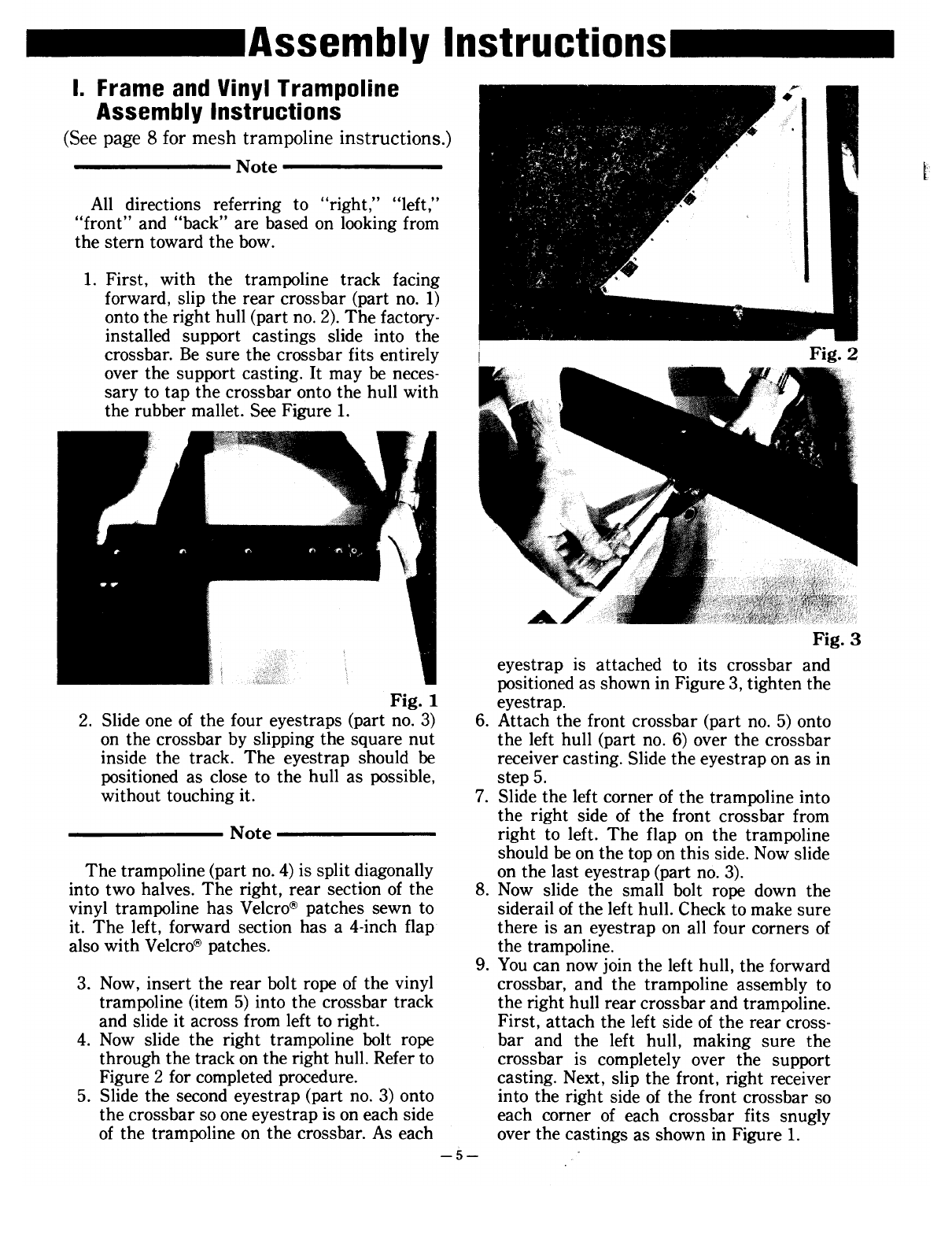
1. First, with the trampoline track facing 11. Attach the crossbar bolts as described in
forward, slip the rear crossbar(part no. 1) steps10and 11of sectionI.
ontothe right hull (part no.2).The factory-
installed support castings slide into the
crossbar.Besure the crossbarfits entirely Note
over the support casting. It may be neces-
sary to tap the crossbaronto the hull with Oncethe boat hasbeensaileda few times it
the rubber mallet. SeeFigure 1. takes on "normal set." In other words, the
2. Slide oneof the four eyestraps(part no.3) crossbarand hulls will setandneedretighten-
on the crossbarby slipping the squarenut ing. This setting also occurs after trailering
inside the track. The eyestrap should be any long distance. This tightening procedure
positionedas closeto the hull as possible shouldbeperformedperiodically.
without touching it.
3. Slidethe meshtrampoline(part no.4),with 12. Securethetrampolinecomersasin step13,
the grommetsaft, into and acrossthe rear sectionI.
crossbar(part no. 1).
4. Slide the secondeyestrap(part no. 3) into This completes assembly of mesh trampo-
position so there is one at eachcomer of lines.
the trampoline. Tighten the eyestraps.
5. Slip the left sideof the rear crossbaronto
the left hull. You may need to use the
rubber mallet to tap the assemblysnug.
CAUTION
Beforecompleting step 5, check the threads
of the crossbar bolts by hand screwing them
into eachanchor bar by hand. If the bolt will
not thread easily,usea tap and dieto clearthe
threads. Use an anti-seizing lubricant such as
Never-Seez@to helppreventcrossthreadingand
galling.
6. Drop in eachof the rear crossbarbolts into
eachsideof the crossbar.DO NOT attach
the anchorbars(part nos.7 and8).
7. Slide both sidesof the trampoline up both
siderailgroovessimultaneously.
-8-

III. Vinyl and Mesh Wing
Trampolines I
Bothmeshandvinylwingtrampolinesassem-
blein the sameway.
1. Lay onewing frame (part no. 12)alongside
each hull as if they were being inserted
into the hulls to make it easierto identify
eachside. The steeply angledend of each
wing shouldbefacing toward the sterns.
2. Lay the wing trampoline (part no. 13)
besideeach wing frame to verify the cor-
rect sideasin Fig. 9. Fig. 10
3. Slide the wing trampolines onto the front
endof the wing frame. Be sure to slide all
threesectionsonto the frame.
Fig. 11
4. Oncethewing tramp is fitted overthewing
Fig. 9 frame, slide the wing frame compression
bar (part no. 14) through the trampoline
openingas in Fig. 12.Attach the opposite
endoverthe casting.
Note
The wing sleevewill only fit when you start
installing it from the front end of the wing
frame. Look closely at the frame and you'll
notice one end has a casting which extends
further from the frame. The sleeveof the tram-
polinewill not slideover this casting.(SeeFig-
ure 10.)Slidethe sleeveonfrom the sideshown
in Figure 11.
Fig. 12
5. The wing now must be sprung enoughto
allow the compressionbar to slip over the
oppositecasting. Use your foot to spread
the wing apart slightly. Slip the compres-
sionbar overthecastingandslowly release
-9-

tension.Repeatthis stepontheother wing.
(SeeFig. 13.)
Fig. 13
6. Now set the wings asidewhile completing
the rest of the assembly.
This completesthe wing frame and trampo-
line assembly.
-10-

IV. Rudder and Tiller Crossbar 3. Repeatthese steps on the other rudder
Assemblies assembly.
4. Attach the left end of the tiller crossbar
(part no. 18marked with a red tag) to the
Note left rudder arm using oneof the tiller con-
necting assemblies(part no. 19)by insert-
The rudder assemblies (part no. 15) are ing the connector bolt through the tiller
markedwith redandgreentags.Redtagsstand crossbarto the tiller arm.
for left side assemblywhile green stands for 5. Placethe flat washer over the threads of
right side.To help makeassemblyeasier,place the bolt followed by the delrin half-round
all items markedwith a red tag behindthe left washer. Then place the crossbar arm on
stern and green-taggeditems behind the right. top of the white delrin washer located
Do not mix differently taggeditems. The fol- betweenthe connectorarm and the tiller
lowing stepsareidentical for both assemblies. arm. Referto Fig. 15.
Note
The rudder castings are installed with three
small,white teflon bearings(part no.16)which
are placedin the casting where the rudder pin
slides through the casting. These bearingsfit
between the rudder pin and the casting with
oneon the top of the bottom casting and two in
the uppercasting.
1. Grasp oneof the rudder pins (part no. 17)
so the end with the small hole and cotter
pin facesup.Removethe cotter pin. Slideit F. 15 F. 16
through both the lower rudder casting Ig. Ig.
bearings and the gudgeo~as.well as the 6. Then placetheoppositewhite delrin washer
~pperassemblyasshow~m FIg. ~4..When overthebolt threadsfollowedbythewasher
mserted: the small hole m the pm should and spring. Securethe assemblywith the
app~ar Just above the top of. the ru~der Nylock nut. Tighten the nut to prevent the
cast~ng.Be sure the small whIte bearIngs assembly from vibrating or backing out.
arem place. SeeFig. 16.
2. Insert the supplied cotter pin into the
rudder pin hole and bendthe cotter pin to
preventrudder pin from backingout of the CAUTION
casting:Referto Fig. 14. Be sure the nut is threaded past the nylon
portion of the bottom of the nut by one com-
pletethread asillustrated in Fig. 17.
Fig. 14
-11-

Fig. 17
7. Repeatsteps4 through 6 on the other side
of the tiller crossbar.
This concludesassemblyof the rudders and
tiller crossbar.
-12-

V. Drain Plugs
Both plugs (part no. 20) are the most often
forgotten item during rigging, but among the
most important. Even championship sailors
forget to put thejr drain plugs in once in a
while, but youcan't govery far with them out. i
Be sure to check your drain plugs beforeyou
leaveshore.Be sure you havegasketsin place
and no sand,or other debris which can permit
leakage,around the opening.Drain plug loca-
tion is next to the lower gudgeonas shown in
Figure 14.
VI. Mast Rigging, Raising and
Lowering
r""""""""""""~ WARNING r""""""""""1 Fig. 18 Fig. 19
I I 5. Attach eachof the two ten-holestay adjus..
I ~eforestarting assembl.y,besure the areain ~ ters (part no. 25) to the bow anchor pi~s.
~ whIch ~ou plan to work ISfree fro.moverheadI Pin the stay adjuster to the anchor pInS
~ power lInes. Contact of a mast wIth a power I with the single openend down. For refer-
I line couldbefatal. I ence,seeFigure28. . .
~ "..." 1 6. Attach eachof the two remaInIngten-hole
. stay adjusters(part no.25)to the eachhull
Note at the chain plate anchor pin. Pin the stay t
. .. adjustersto the anchorpinswith the single
The WIreset for the Hoble17consIstsof the open end down. For reference,seeFigure
following: Trapeze wires; Shrouds; Forestay; 21. j
Bridles. The trapeze ':lires and the .l~ft and 7. The main halyard (70'x 3/16" line) should
right shrouds are unIversal. In addItIon, all be threaded through the top of the mast '
three forestay/bridle wires are the same length. and back down through the middle sheave :
at the base of the mast. If it is not, thread it
1. Uncoil the supplied wire set (part no. 21) now. Check the halyard shackle and ring to
and.lay the wires on the groun.din the fol- besurethey areattachedto the endexiting I
loWIngpattern from left to rIght: a. left themasthead. ,
trapezewire, b..left s~roud wi~e,c. oneof 8. Checkthe main halyard shackleand ring.
the forestay/brldle WIres,d. rIght shroud Makesurethe halyard is securelytied with
wire, e. right trapezewire. a halyard knot as described.(See"Knots"
2. Slide the wir~s onto the large bell shackle on page17.)Besurethe halyard ring hasa
(part no. 22) m the samepattern as they twist shackleattachedto it.
were laid out in step 1. Then attach the
shackleto the mast tang (part no. 23).Be
sure the trapezewires are attachedsothe Note
handle end is not the end closest to the
tang.Referto Fig. 18. Makesurethe knot is assmall aspossibleso
3. Securethe shacklepin to the shacklewith the ring will beable to clear the halyard hook
bailing wire. Tie the shackleto the pin, to when fully hoistedasseenin Fig. 20.The knot
preventthe pin from backingout. shown is much larger than that describedon
4. Use the small bell shackle(part no. 24) to page17.Usethe halyard knot.
attach the two bridles to the forestay.
Securely tighten the shackle with pliers 9. Tie a figure-eight knot (see "Knots" on
(seeFig. 19). page17)at the bareendof the halyard.
-13-

r"""""""""""""""". WARNIN G"""""""""""""""""1
.. I Beforeraising the mast, be sure the area is I
. free from overheadpower lines. Contact of a I
I mast with a powerline could befatal. I
, ~
15. Locatethe mast steppin (part no.28)from
the mastbaseor rig kit.
16. Rotatethe mast so the arrows are aligned
and slip the mast baseover the mast step
ball. Then insert the step pin. Securethe
pin in placeby inserting the ring through
the hole in the endof the pin. (SeeFig. 22
ring not secure.)
..,~-"_..,',."._"
~l
Fig. 20 Fig. 21
CAUTION
Be sure the mast tip is supportedby a rear
mast support, a box, a ladder or a friend soits
weight doesnot lay on the tiller crossbar or
directly on the boat during the following pro-
cedure. Fig. 22
10. Position the mast so the mast tip points 17. To raisethe mastalone,attach the shackle
toward the sterns and the mast base is endof the main halyard to the right bow's
next to the mast step ball on the forward ten-holeadjuster (Fig. 27),beingcertain it
crossbarso the yellow arrows are aligned, passesoverboth the left andright shrouds,
Check both shroud wires to be sure they trapezewires and the forestay.
arenot fouledor wrappedaroundthe mast.
11. Now slip the white shroudcovers(part no.
27), thimble end first, over each shroud CAUTION
cover through the smallest openingin the
endof the cover. The first time you try to raisethe mast,have
12. Attach both left and right shrouds to the the helpof two friends available.Alsocheckthe
ten-hole stay adjusters on corresponding gooseneckto becertain it is not positionedat an
sidesof the boat.Placeeachshroudwire in angle forward or away from the top of the
r the st.ayadjuster and insert the clevis pin mast.!f .it is, tilt or ti,eit to the rotation arm to
\ and rIng (part no. 26).Usethe fourth hole preventIt from touchIngthefront crossbardur-
from the top of eachstay adjuster.(See ingraising. '
f Figure 21.)
13. Clear each trapeze wire so they are not
fouledaroundthe oppositeshroudor the ~ WARNING"""""""""""""""""i
forestay. I I
14. Check the forestay to be certain it is not. Beforeraising the mast, be sure the area is I
fouledaroundthe shroudsduring the mast. free from overheadpower lines. Contact of a I
raising. Be sureit remainsclear. I mast with a powerline could befatal. I
' 1.
-14-

18. Step onto the trampoline and place your
foot on the rear crossbar.
19. Keepingall the weight on that foot, lift the
mast being sure to keep it rotated so the
yellowarrowsarealigned.Referto Fig.23. t-
.
I
Fig. 26
with onehand to stabilize the mast onceit
is completely up, while you perform the
next stepwith the other hand..
22. Take up the slackin the main halyard (Fig.
Fig 23 27) and secure the main halyard to the
. . . mast rotation bar or the mast base, which-
20. S~I~g your arms over your head .while ever is most comfortable for you. Tie it
shIftIng your bodyunderthemast.(FIg.24) very securelywith a doubleor triple hitch
(see"Knots" on page17). Remember,the
knot you tie here will have to support the
total weight of the mast onceyou release
forward pressure.Due to the distanceand
characteristics of the line, try to pull some
stretch into it.
Fig. 24
21. Pushthe mast upandoveryour head,then
walk it forward grasping hand-over-hand
as you go. (Figs. 25, 26) If you are raising
the mast alone,maintain forward pressure
<II
Fig. 27
23. When you're certain the halyard is secure,
walk forward, clear the bridles of any
wraps and attach the clearedbridle to the
ten-holeadjuster you installed during step
6 of chapter VI. Insert the clevis pin and
Ig. - 15-

ring (part no. 26), using the fourth hole
from the top.(Fig.28) 5w..",,"
J . '"
. " ~~ "
Fig. 28
24. Now slowly releasethe main halyard. Let
about2 feetof the halyard line run through
the sheaveand tie the rest securelyto the
mast rotation bar or the mast baseas in
step 23 of this chapter. The angle of the
mastwill shift from left to right asthe load
is shifted from the main halyard to the side
bridle wire.
25. Locatethe other bridle wire. Clear the bri-
dle of any wraps and attach the cleared
bridle to the right ten-hole adjuster you
installed during step 6 of this chapter VI.
Insert the clevis pin and ring (part no.26),
using the fourth holefrom the top.
26. Releasethe twist shackleendot1temain
halyard from the right ten-holeadjuster.
27. Securethe shackledend of the main hal-
yard to the boatto preventit from slipping
to the top of the mast accidentally.
-16-

VII. Trapeze Wires
1. Lead the trapeze shock cord (part no. 29)
through the grommet on the forward out-
board side of the trampoline, then under
the trampoline and through the opposite
grommet.
2. Clear the trapezehandles so they lead to
the outsideof the shrouds.Then tie the 3-
foot length of quarter-inch line (part no.30)
to the dogbone or the J and H handle
(optional) with a bowline knot. After the
line is led through the thimble on the end
of the trapeze wire, attach the rope lock
(part no.32).Now tie the endof the line to
the shockcord with another bowline knot.
(The completeassemblyis shown in Fig.
29.)
Fig. 29
~
r
-17-

VIII. Sail and Battens shackletightly. Feedthe sail luff through
the sail feederon the mast(Figure31).Use
1. Spreadthe sail (part no.33)out flat on the the halyard to gradually pull the sail up
ground and lay each batten (part no. 34) while guiding the luff into the feeder.If the
over the correct battenpocket. sail binds at the feeder,backit down a bit,
then continuepulling it up.
CAUTION
It's important that the sail be perfectly flat
on the ground. A wrinkled sail could leadto a
tear in the sail fabric when the battens are
pushedinto their pockets.
Note
Whenbattensarelaid overthecorrectpocket,
two to three inchesof the batten endshouldbe
laying overthe outer edgeof the sail.
2. Start at the top of the sail and insert each
batten into its pocket being sure that the
endof the battenwith the flat endcapslips
in first.
3. Tie eachbatten snuglywith thebattenties .
as shown in Figure 30. (Batten ties have .
been attached to the corner of the sail FIg. 31
beforeshipping.)Battensareat the correct 6. When the sail nears the halyard hook at
tightnesswhen the battenhasremovedthe the top of the mast, gently pull the sail up
wrinkles from the pocket. Proper tension and listen for a slight "click" as the ring
will vary with wind conditions. passesthe small hook. (SeeFig. 32) Then
'I rotate the mast to the right by pushing on
, the mast rotation arm at the mast base.
Then releasethe halyard. When you think
it has locked,pull down on the bottom of
the sail to becertain.
Note
If you raise the sail too quickly or pull too
hard, you will slidethe hookpast the lock.The
ring will then slide back down past the lock
assembly.Usea gentletouchwhen nearingthe
lock assemblyand listen for the click. When
Fig. 30 disengagingthe ring, pull the halyard so the
4. Point your Hobie 17 into the wind. This hook passesth~ lock, thus allowing the arm to
allows you to pull up the sail easily and closeandthe rIng to passthe hook.
preventsthe boatfrom sailing away.
5. Check the halyard to be sure it is not
wrappedaroundthemastor shrouds.Twist-
ing the main halyard approximately six
times in a clockwise direction may facili-
tate halyard locking. Then attach the hal-
yard to the top of the sail and securethe-18-
Other manuals for 17
2
Table of contents
Other Hobie Boat manuals

Hobie
Hobie Bravo User manual

Hobie
Hobie TriFoiler User manual

Hobie
Hobie Mirage Drive User manual

Hobie
Hobie Mirage Adventure Island User manual

Hobie
Hobie T1 User manual

Hobie
Hobie kayak User manual

Hobie
Hobie Mirage Pro Angler 17T User manual

Hobie
Hobie 14 Turbo User manual

Hobie
Hobie Mirage Tandem Island User manual

Hobie
Hobie WILD CAT User manual
Popular Boat manuals by other brands

Cruisers Yachts
Cruisers Yachts 420 Express Series owner's manual

Sevylor
Sevylor 1 Person Sit On Top Kayak (Non Covered) instructions

Agilis Jettenders
Agilis Jettenders 330 Owner's handbook

Jeanneau
Jeanneau Leader 40 owner's manual

Boston Whaler
Boston Whaler 190 Outrage Service manual

Seamax
Seamax AIR230 user manual