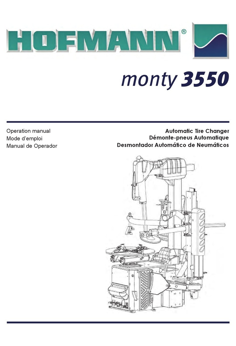
Hoffmann MONTY 3550 TTGP User manual

Passenger Tire Changers Service Manual 07-13 Rev.B
1
PASSENGER
TIRE CHANGERS
SERVICE MANUAL
DO NOT COPY NOR DISTRIBUTE
No part of this document may be photocopied, reproduced, or translated
without prior written consent of Snap-on

Passenger Tire Changers Service Manual 07-13 Rev.B
2
BLANK PAGE

Passenger Tire Changers Service Manual 07-13 Rev.B
3
TABLE OF CONTENTS
CHAPTER 1 INTRODUCTION Pag. 5
1.1 General Pag. 5
CHAPTER 2 TOOLS AND SAFETY Pag. 5
2.1 Tools and special tools required Pag. 5
2.2 Important safety instructions Pag. 7
2.3 Electrical safety precautions Pag. 7
CHAPTER 3 AC/DC POWER DISTRIBUTION Pag. 8
3.1 Lockout and/or tagout system procedure Pag. 8
3.2 Electrical requirements Pag. 8
3.3 AC Theoy of operation Pag. 8
CHAPTER 4 ELECTRIC SECTION Pag. 11
4.1 Power supply cable and plug on electronic Inverter: check and replacement Pag. 13
4.2 Power supply cable and plug on Inverter switch: check and replacement Pag. 13
4.3 Inverter switch S1: check and replacement Pag. 15
4.4 Main rotary switch Q2: check and replacement Pag. 15
4.5 Turntable motor M1 cable: check and replacement Pag. 16
4.6 Turntable motor M1and belt :check and replacement Pag. 17
CHAPTER 5 ELECTRONIC SECTION Pag. 20
5.1 Inverter T1: check and replacement Pag. 20
5.2 Inverter T1: Firmware update Pag. 22
5.3 Turntable potentiometer: check and replacement Pag. 29
5.4 Potentiometer adjustment with software 1.4.5 Pag. 33
CHAPTER 6 PNEUMATIC SECTION Pag. 34
6.1 Pneumatic function Pag. 34
6.2 Air filter – lubricator assy : check and replacement Pag. 35
6.3 Tilting post cylinder: check and replacement Pag. 36
6.4 Vertical rod blocking cylinder on 26” : check and replacement Pag. 39
6.5 Vertical rod blocking cylinder on 22” : check and replacement Pag. 41
6.6 Horizontal blocking cylinder on 26”: check and replacement Pag. 44
6.7 Horizontal blocking cylinder on 22: check and replacement Pag. 44
6.8 Vertical rod lift cylinder: check and replacement Pag. 49
6.9 Valve with yellow button: check and replacement Pag. 50
6.10 Handle with valve: : check and replacement Pag. 52
6.11 Automatic tool cylinder: check and replacement Pag. 53
6.12 Automatic tool cylinder valve: check and replacement Pag. 55
6.13 Bead breaker cylinders: check and replacement Pag. 56
6.14 Turntable cylinders: check and replacement Pag. 58
6.15 Manifold revolving: check and replacement Pag. 60
6.16 Foot pedal assembly valves: check and replacement Pag. 64
6.17 Wheel lift cylinder: check and replacement Pag. 65
6.18 Wheel lift valve: check and replacement Pag. 67
6.19 MH cylinder: check and replacement Pag. 68
6.20 MH cylinder control valve: check and replacement Pag. 69
6.21 Bead inflating valve: check and replacement Pag. 70
6.22 Bead blaster valve and air tank: check and replacement Pag. 72
6.23 Air control: check and replacement Pag. 72
6.24 Manometer: check and replacement Pag. 73
6.25 spiral pipes: check and replacement Pag. 75
CHAPTER 7 MECHNICAL SECTION Pag. 78
7.0 Mechanical section Pag. 78
7.1 Opening arm bushings # 1-10065A check and replacement Pag. 78
7.2 Automatic tool: check, replacement and adjustment Pag. 80
7.3 Standard tool: check, replacement and adjustment Pag. 85
7.4 Horizontal arm rollers: check and adjustment Pag. 92

Passenger Tire Changers Service Manual 07-13 Rev.B
4
7.5 Gear box: check and replacement Pag. 93
7.6 Turntable jaws: Check, replacement and adjustment Pag. 93
CHAPTER 8 TROUBLE SHOOTING Pag. 97

Passenger Tire Changers Service Manual 07-13 Rev.B
5
CHAPTER 1
INTRODUCTION
1.1 GENERAL
This Service Manual describes maintenance, check and repair operations of the passenger tire changer under
Hofmann, John Bean and Boxer brands and is for use of qualified and trained personnel only.
Keep this manual constantly updated, by adding Service Bulletins related to the tire changers.
IMPORTANT!
The identification data of each machine are printed on a adhesive label attached to the cabinet of the machines.
The serial number is a sequence of figures standing for the manufacturing month and year the first four numbers,
followed by the machine part number and finally the progressive serial number of the machine manufactured with
this specific part number.
In the sections dedicated to the check, replacement and adjustment of the components there will be reported some
symbols as follows:
: Total amount of working time required to check, replace and adjust the components: this time is
calculated considering the standard installation condition provided by the operator manual.
: List of tools required to perform the work.
: Information related to the possible failure/malfunction caused by the component
CHAPTER 2
TOOLS AND SAFETY
2.1 TOOLS AND SPECIAL TOOLS
To repair and/or check these tire changer, the following standard tools are required:
Keys : 6mm to 30mm
Tube type keys : 7mm to 17mm
Allen keys : 2.5 mm to 12 mm
Socket keys : 10mm to 27mm
Allen socket keys : 4mm to 12mm
Screw drivers : Flat bed and Phillips from 1 to 5
Multimeter : AC, DC, A, Ohm, pF
Lotctite and mechanical extractor
Special tools that are required for specific tasks are:
20mm Ring nut socket keys:
Use these keys to tight or loose the knees ring nuts.

Passenger Tire Changers Service Manual 07-13 Rev.B
6
Ring to adjust the turntable run out and the rim contact #
0013549:
Use the ring to adjust the turntable run out and to check the proper
contact of the jaws to the rim.
Electronic dynamometric key.
Use this key to lock the potentiometer set screw with proper torque.
Air pressure reducer # 4002916.
Use this reducer to adjust the tilting post end stroke screws and the
turntable jaws.
Dynamometric key:
Use this key to lock the screws with the proper torque.

Passenger Tire Changers Service Manual 07-13 Rev.B
7
Gauge with magnetic basement:
Use this gauge to check the run out of the turntable.
2.2 MPORTANT SAFETY INSTRUCTIONS
The units are CE or UL approved, but whenever using this equipment basic safety precautions should always be
followed, including the following:
1. Read all instructions.
2. Do not operate equipment with a damaged power cord or if the equipment has been damaged until it has been
examined by a qualified authorized service technician.
3. If an extension cord is used, a cord with a current rating equal to or more than that of the machine should be
used. Cords rated for less current than the equipment may overheat. Care should be taken to arrange the cord
so that it will not be tripped over or pulled.
4. Always unplug equipment from electrical outlet when not in use. Never use the cord to pull the plug from the
outlet. Grasp plug and pull to disconnect.
5. To reduce the risk of fire, do not operate equipment in the vicinity of open containers of flammable liquids
(gasoline).
6. Keep hair, loose fitting clothing, fingers and all parts of the body away from moving parts.
7. To reduce the risk of electric shock, do not use on wet surfaces or expose to rain.
8. Do not hammer on or hit any part of the control box.
9. Do not allow unauthorized personnel to operate the equipment.
10. Use only as described in this manual. Use only manufacturer’s recommended attachments.
11. Always securely lock the wheel before starting the operation.
12. ALWAYS WEAR SAFETY GLASSES. Everyday eyeglasses only have impact resistant lenses, they are NOT
safety glasses.
13. Tire changer is for indoor use only.
2.3 ELECTRICAL SAFETY PRECAUTIONS
Make sure the tire changer is unplugged before disconnecting any wires in preparation for replacing any electric
mechanic components, cables or other items within the unit

Passenger Tire Changers Service Manual 07-13 Rev.B
8
CHAPTER 3
AC/DC POWER DISTRIBUTION
3.1 LOCKOUT AND/OR TAGOUT SYSTEM PROCEDURE
1. Notify all affected employees that a lockout or tag-out system is going to be utilized and why. The authorized
employee should know the electrical power the machine uses and it’s hazards.
2. If the machine or equipment is running, shut it down by the normal stopping procedure (depress the stop button,
open toggle switch, etc.).
3. Use appropriate devices to isolate the equipment from the power source(s). Stored energy (such as that in
springs, elevated machine members, rotating flywheels, hydraulic systems, and air gas, steam or water pressure,
etc.) must be dissipated or restrained by methods such as repositioning, blocking, bleeding down, etc.
4. Lockout and/or tag-out the energy isolating devices with individual lock(s) or tag(s).
5. After ensuring that no personnel are exposed, and as a check on having disconnected the energy sources,
operate the push button or other normal operating controls to make certain the equipment will not operate.
CAUTION: RETURN OPERATING CONTROL(S) TO “NEUTRAL” OR “OFF” POSITION AFTER THE TEST [DE-
ENERGIZED STATE].
6. The equipment is now locked out or tagged out.
3.2 ELECTRICAL REQUIREMENTS
NOTE: ANY ELECTRICAL WIRING MUST BE PERFORMED BY LICENSED PERSONNEL.
ALL SERVICE MUST BE PERFORMED BY AN AUTHORIZED SERVICE TECHNICIAN.
Check on the plate of the machine that the electrical specifications of the power source are the same as that of the
machine.
NOTE: ANY ELECTRICAL OUTLET INSTALLATION MUST BE VERIFIED BY A LICENSED ELECTRICIAN
BEFORE CONNECTING THE TIRE CHANGER.
NOTE: ENSURE THAT THE OUTLET HAS AN AUTOMATIC GROUND FAULT CIRCUIT BREAKER WITH A
DIFFERENTIAL CIRCUIT SET AT 30 MA.
3.3 AC THEORY OF OPERATIONS
Always use the “One Hand Rule” when working with AC voltages by keeping one hand in your pocket or behind
your back. Before removing wires from the tire changer, always verify that the unit is “OFF”. Turn off the Main Power
Switch on the back and unplug the AC power cord from the AC outlet.
AC DISTRIBUTION
The tire changers are equipped by single phase and three phases turntable motors.
The voltage at which the machine is wired is printed on the serial number plate and on a tag at the end of the power
cord.
The single phase power cord has 3 wires:
N Neutral
L1 Phase
PE (yellow/green) Ground
The three phase power cord has 4 wires:
L1,L2,L3 Phases
PE (yellow/green) Ground
The 3 phases machines can be wired at two different voltages:
400 VAC (suitable for 360-415V range).

Passenger Tire Changers Service Manual 07-13 Rev.B
9
230 VAC (suitable for 200-250V range).
The machines can be equipped with 50 or 60 Hertz motors.
•On machines with normal electric reversing switch, the AC power supply, (+/-10% compared to the nominal
one) is directly supplied to the switch.
•On machines with inverter the 230 (+/-10%) AC voltage comes in through a “ON/OFF” Power Switch placed on
Inverter cover and immediately is sent via to an anti disturb filter to the Electronic Inverter.
MAIN SWITCH Q1 ( MACHINES WITH ELECTRONIC INVERTER ONLY)
Main switch is used to supply all electric components of the machine.
INVERTER T1
It converts the 230V-1Ph in 230V-3Ph to be supplied to the turntable motor M1 and
also changes the motor rotational speed from 50 to 100Hz.
TURNTABLE POTENTIOMETER P1
The potentiometer is of 20K type and forwards the rotational and speed
inputs to the inverter T1 for the motor M3.

Passenger Tire Changers Service Manual 07-13 Rev.B
10
INVERTER SWITCH S1
The inverter switch S1 controls the rotation and the speed of the
turntable motor. There are single phase, 3 phase, single speed
switch and 3 phase 2 speed switch.
TURNTABLE MOTOR M1
On inverter switch models it can be single or 3 phase, single speed
or 2 speed.
Three phase motors can be wired at star or delta . They are supplied by the inverter switch.
On models with electronic Inverter, the motor is supplied by the inverter T1. The motor is wired at 230Volts 3phase.

Passenger Tire Changers Service Manual 07-13 Rev.B
11
CHAPTER 4
ELECTRIC SECTION
WARNING!
BEFORE APPROACHING THE ELECTRIC PARTS OF THE MACHINE,
DISCONNECT THE MACHINE FROM ELECTRIC SUPPLY
Very often electric failures are only caused by loosened wires or connectors not well fitted.
Therefore it is VERY IMPORTANT BEFORE STARTING WITH ANY CONTROL AND/OR REPLACEMENT VERIFY
IF ALL WIRES AND CONNECTORS ARE WELL FITTED.
4.1 POWER SUPPLY CABLE ON ELECTRONIC INVERTER: CHECK AND REPLACEMENT
: 1h
: Allen keys of 3 and 5mm, small and medium screwdriver, medium cross screwdriver, faston pliers, scissors,
pliers, multimeter.
: Defective power supply cable and plug may cause the following malfunction:
1. Turning the switch on, the turntable does not turn in any direction.
2. Sometime the turntable does not turn.
3. The shut off switch of the shop shuts down.
TO CHECK THE CABLE:
Disconnect power supply.
Remove the plug form the wall.
Remove the electric box from the cabinet.
Loosen the screw to remove switch knob.

Passenger Tire Changers Service Manual 07-13 Rev.B
12
Remove the disc acting with a screwdriver on the side tabs
Loose the screws and remove the frame switch.
Take the switch out from the inverter box.
Check wires continuity from power supply plug to main switch wires terminals.
Cross the wire check to make sure that any wire in short circuit.
IMPORTANT! TO CHECK GROUND (YELLOW/GREEN) WIRE, DISCONNECT THE WIRE END FROM THE
TERMINAL BLOCK.
TO REPLACE THE CABLE:
Disconnect the power supply wires from the plug and switch terminals.
Disconnect the ground wire from terminal block.
Release cable strain relief from the inverter box.
Remove plug from cord and take the defective cable away.
Insert the new cable through the strain relief.
IMPORTANT! USE ONLY APPROVED CABLES, PLUGS. GROUND WIRE MUST BE LONGER THAN THE
OTHER ONES.
Fix new faston on inside cable ends and connect them to the switch terminals and to the plug.
Fix the main switch to the electronic box.
Install the disc.
Mount again the switch knob and cover of the screw.
Connect the ground wire to ground terminal block.
Install plug.
Tighten strain relief FIRMLY.
Plug the machine to the wall.
Check if the machine works fine.
Disconnect the power supply.
Fix the inverter box again to the cabinet.

Passenger Tire Changers Service Manual 07-13 Rev.B
13
4.2 POWER SUPPLY CABLE ON INVERTER SWITCH: CHECK AND REPLACEMENT
: 1h
: Allen keys of 6mm, 7,8,13mm tube type key, medium cross screwdriver, pliers, multimeter.
: Defective power supply cable and plug may cause the following malfunction:
1. Turning the switch on, the turntable does not turn in any direction.
2. Sometime the turntable does not turn.
3. The shut off switch of the shop shuts down.
4. Turntable Motor burning.
5. Turntable motor run with 1 or 2 phases
TO CHECK THE CABLE:
Disconnect power supply.
Remove the plug form the wall.
Remove the side panel from the machine.
Remove the foot pedal assembly from the cabinet.
Extract the foot pedal assembly from the cabinet.
Disconnect the linkage from the switch shaft and disconnect the ground wires.

Passenger Tire Changers Service Manual 07-13 Rev.B
14
Unscrew the screws that hold the switch to the bracket and remove the switch from the bracket.
Remove the protection from the switch and disconnect the wires L1, L2 and L3 from the terminals and from the
plug.
Take a multimeter and select it in MOhm.
Place the multimeter terminals on the ends of the same
wire to check the continuity.
Cross the wire check to make sure that any wire is in short
circuit.
IMPORTANT! TO CHECK GROUND (YELLOW/GREEN)
WIRE, DISCONNECT THE WIRE END FROM THE
TERMINAL BLOCK.
TO REPLACE THE CABLE:
Release cable strain relief from the power cord.
Remove plug from cord and take the defective cable away.
Insert the new cable through the strain relief.

Passenger Tire Changers Service Manual 07-13 Rev.B
15
IMPORTANT! USE ONLY APPROVED CABLES, PLUGS. GROUND WIRE MUST BE LONGER THAN THE
OTHER ONES.
Fix new faston on inside cable ends and connect them to the switch terminals and to the plug.
Place the rubber protection on the switch.
Connect the ground wire to ground terminal block.
Install the switch on the bracket..
Mount again the switch linkage and secure it with the screw.
Tighten strain relief FIRMLY.
Install the foot pedal assembly to the cabinet.
Plug the machine to the wall.
Check if the machine works fine.
Disconnect the power supply.
Install the side panel to the machine.
4.3 INVERTER SWITCH S1: CHECK AND REPLACEMENT
: 1h
: Allen keys of 6mm, 7,8,13mm tube type key, medium cross screwdriver, pliers, multimeter.
: Defective power supply cable and plug may cause the following malfunction:
1. Turning the switch on, the turntable does not turn in any direction.
2. Sometime the turntable does not turn.
3. The shut off switch of the shop shuts down.
4. Turntable Motor burning.
5. Turntable motor run with 1 or 2 phases
TO CHECK THE INVERTER SWITCH:
Unplug the machine from the wall.
Disconnect the wires from the motor 4.2.
By a multi meter make sure that there is continuity between the 3
phases on the switch and the wires of the 1st speed of the motor,
pressing the rotational pedal in the 1st stage.
If there is not continuity on all 3 phases replace the switch.
TO REPLACE THE INVERTER SWITCH:
Follow 4.2.
4.4 MAIN ROTARY SWITCH Q1: CHECK AND REPLACEMENT
: 0,5h
: Allen keys of 3 and 5mm, small and medium screwdriver, medium cross screwdriver, faston pliers, scissors,
pliers, multimeter
: Defective main switch may cause the following malfunction:
1. Turning the switch on the turntable does not turn at all.
2. Turning the machine on the shut off switch of the shop shuts down.
TO CHECK THE SWITCH:
Disconnect power supply.
Remove the switch from the electronic box 4.1
Disconnect all wires from the main switch and remove it with a
screwdriver.
Turn switch to “Off”. Check that there is no continuity (Ω =infinity)
between any terminals 1,2,3 and 4.
Turn switch to “On”. Check that there is continuity between
terminals 1-2 and 3-4 (Ω = 0 ~ 0,3) and discontinuity between
terminals
1-3 and 1-4, as well as 2-3 and 2-4
If there is continuity the switch is in short circuit. It must be

Passenger Tire Changers Service Manual 07-13 Rev.B
16
replaced.
TO REPLACE THE SWITCH:
Check that the tabs for contacts on the new switch are correctly oriented.
Connect wires ends FIRMLY to the new switch terminals as shown in the appropriate electric diagram.
Mount the switch to the electronic box 4.1.
Connect the machine to the power supply.
Check if the machine works fine.
Disconnect the power supply.
Fix the inverter box again to the cabinet.
4.5 TURNTABLE MOTOR M1 CABLE: CHECK AND REPLACEMENT
: 1h
: Medium screwdrivers, medium cross screwdrivers, 7mm tube type wrench, 3mm allen key, pliers, multimeter
: Defective chuck motor cable may cause the following malfunction:
1. Low rotational torque.
2. Noisy motor.
3. Motor damaging (burning).
4. Turning the machine on the shut off switch of the shop shuts down.
5. The turntable does not turn at all.
6. Damaged Inverter.
TO CHECK THE CABLE ON ELECTRONIC INVERTER:
Disconnect power supply from the wall.
Remove the electric box from the cabinet 4.1.
Disconnect the wires white, brown and black from the Inverter.
Remove the side panel from the cabinet to access to the turntable motor M1

Passenger Tire Changers Service Manual 07-13 Rev.B
17
Remove the motor terminals cover and disconnect all wires from
terminals.
Select the multimeter in Ohm and check if there is continuity
between ends of each wire.
Cross the wire check to make sure that wires are not in short
circuit.
TO CHECK THE CABLE ON INVERTER SWITCH:
Remove the foot pedal assembly from the cabinet 4.2
Remove the switch from the pedal assembly 4.2
Remove the motor terminals cover and disconnect all wires from terminals.
Select the multimeter in Ohm and check if there is continuity between ends of each wire.
Cross the wire check to make sure that wires are not in short circuit.
TO REPLACE THE CABLE ON ELECTRONIC INVERTER:
Release cable strain relief on the electric box and on the motor.
Take the wrong cable away.
Insert the new cable through the strain relief.
IMPORTANT! USE ONLY APPROVED CABLE. GROUND WIRE MUST BE LITTLE
LONGER THAN THE OTHER ONES TO ALLOW THE GROUND IN CASE OF PHASE
CABLE BREAKAGE.
NOTE: Before connecting the wires ends, tighten all terminals nuts on the motor.
Fix new fastons to the cable ends.
Connect the wires to the motor and inverter terminals.
Mount the motor terminal cover.
IMPORTANT: WHEN REMOUNTING THE MOTOR TERMINALS COVER BE CAREFUL NOT TO CRUSH
WIRES.
Plug the machine to wall.
Turn the machine on and check if it works fine.
Disconnect the machine from the power supply.
Mount the side panel to the cabinet.
Fix the electric box to the cabinet again 4.1
TO REPLACE THE CABLE ON INVERTER SWITCH:
Replace the cable following 4.2
4.6 TURNTABLE MOTOR M1 AND BELT: CHECK AND REPLACEMENT
: 1h
: 2 End keys 13,1 end key 17mm, medium cross screwdriver, 7mm tube type wrenches, 3 mm allen key,
multimeter, loctite, extractor.
: Defective centerpost motor may cause the following malfunction:
1. Motor is noisy.
2. Motor is burnt.
3. Low turntable torque.
TO CECK THE MOTOR WHEN IT SHOWS LOW TORQUE OR IT IS NOISY:
Refer to 4.5

Passenger Tire Changers Service Manual 07-13 Rev.B
18
TO CHECK THE MOTOR WHEN IT IS NOISY:
Disconnect power supply from the wall.
Remove the side panel to access to the motor 4.4.
Unscrew the 8mm nuts to get motor loose.
Turn the front nut to move the motor support and loose the belt.
Use a screwdriver in between pulley and belt and rotate the pulley to remove the belt.
Place a screwdriver through the fan protection and turn the motor pulley by hand to make sure that the fan is
well blocked to the motor shaft.
Plug the machine to the power supply.
Turn the machine on.
MACHINE UNDER TENSION DANGER OF ELECTRIC SHOCK
Press the rotational pedal to run the motor to verify if it is noisy
TO CHECK THE MOTOR WHEN IT IS BURNT ON ELECTRONIC INVRTER:
Disconnect the power supply from the machine.
Refer to paragraph 5.4 to make sure about the wiring and the cable.
Remove all wires and connections from the motor terminal.
Select the multimeter in Ohm and check if there is continuity between all terminals of the motor: if there is
continuity the motor must be replaced.
TO CHECK THE MOTOR WHEN IT IS BURNT ON INVRTER SWITCH:
Unplug the machine from the wall.
Disconnect the wires from the motor.
By a multi meter make sure that there is continuity between the 3 phases on the switch and the wires of the 1st
speed of the motor, pressing the rotational pedal in the 1st stage.

Passenger Tire Changers Service Manual 07-13 Rev.B
19
If there is continuity on all 3 phases replace the motor.
TO REPLACE THE MOTOR:
Place some piece of woods under the motor to avoid any
dangerous falling on the foot pedal assembly. The top one should
be longer in order to be used to lift the motor during the mounting.
Unscrew the two front bolts from the manifold to release the motor.
IMPORTANT! HOLD THE MOTOR WITH A HAND TO AVOID ANY
POSSIBILITY OF FALLING THAT COULD DAMAGE THE FOOT
PDAL ASSY.
Disconnect the wires from terminals.
Remove the pulley set screws.
Remove the pulley by using an extractor tool.
Remove the motor from its support.
Take the new motor.
Install the pulley by using rubber hammer.
NOTE: The mounting of the new pulley must be done very carefully in
order to avoid motor bearings damaging.
NOTE: Before connecting the wires ends, tighten all terminals nuts.
Connect the wires FIRMLY to motor terminals following the
voltage at which the machine is supplied.
Fix the motor on its support.
Install the motor assy on the machine and lock it firmly.
Mount the belt.
Adjust the belt tension
Plug the machine to the wall.
Turn the machine on.
MACHINE UNDER TENSION DANGER OF ELECTRIC SHOCK
Check the rotation way of the motor: If it is wrong reverse only two motor wires.
Turn the machine off and unplug it from the wall.
Mount the motor terminals cover.
IMPORTANT: WHEN REMOUNTING THE MOTOR TERMINALS COVER BE CAREFUL NOT TO CRUSH
WIRES.
Mount side panel to the cabinet.
Turn the machine on again and check if it works fine again.

Passenger Tire Changers Service Manual 07-13 Rev.B
20
CHAPTER 5
ELECTRONIC SECTION
WARNING!
BEFORE APPROACHING THE ELECTRONIC PARTS,
DISCONNECT THE MACHINE FROM POWER SUPPLY.
5.1 INVERTER T1: CHECK AND REPLACEMENT
: 1h
: Voltmeter, 3mm allen key, 8mm tube type key, pliers.
: Defective inverter may cause the following malfunction:
1. Motor does not turn at all.
2. Motor turns in slow speed only
3. Motor turns in high speed only.
4. Motor turns in reverse direction only.
5. Turntable does not turn in second speed.
6. The shut off switch of the tire shop shuts off.
TO CHECK THE INVERTER:
Turn the machine off.
Remove the electric box from the cabinet 4.1.
Disconnect the wires and the connectors from the inverter terminals
marking the position.
Turn the machine on.
Take the multimeter and select it in VAC up to 400.
Position the multimeter terminals on the output terminals of the inverter.
Press the rotational pedal and check if the output is 230VAC on all three
terminals
IMPORTANT! BEFORE REPLACING THE INVERTER MAKE SURE THAT
THE TURNTABLE MOTOR AND ITS WIRES ARE FINE.
TO REPLACE THE INVERTER:
Disconnect the power supply from the machine.
Unscrew the rear screw to remove the Inverter from the box.
Table of contents
Other Hoffmann Tyre Changer manuals
Popular Tyre Changer manuals by other brands

Base Line
Base Line 300 Safety Instructions, Set Up Instructions, Operation Instructions, Maintenance Instructions

Launch
Launch TWC Series manual

Ken-Tool
Ken-Tool T600 owner's manual

Bosch
Bosch TCE 4460 Original instructions

Rene Herse Cycles
Rene Herse Cycles ANTELOPE HILL Mounting instructions

Corghi
Corghi ARTIGLIO 50 Operator's manual