HOKLARTHERM Riga S User manual

ALUMINIUM
GREENHOUSE
Riga S/Riga
Basic kit
assembly instructions
Subject to technical changes!
model Riga S
Width 2,32 m / 7ft 8in
www.exaco.com
877-760-8500
Assembly Animation Video
is available on our YouTube page,
find the link at www.exaco.com or
scan the QR code below:
model Riga
Width 2,96 m / 9ft 8in
Version 4.2021

Table of Contents
Before You Begin…………………………………………………………………………….....2-3
Polycarbonate Information………………………………………………………………………..4
Foundation Frame (optional accessory)………………………………………………………5-6
Site Planning and Preparation with Foundation Measurements………………………………7
Main Box Contents – Basic Kit………………………………………………………………...8-9
Gable Assembly……………………………………………………………………………….10-11
Roof Windows
Roof Window Parts/Assembly………………………………………………………12-14
Roof Window Auto Opener………………………………………………………….15-16
Wind Restraints for High Wind (optional)………………………………………………17
Door Assembly
Door Bottom Half………………………………………………………………….…..18-19
Door Top Half …………………………………………………………………………20-21
Door Catch Installation…………………………………………………………………...22
Rear Window…………………………………………………………………………………...23-24
Putting It All Together
Assembling the Eaves/Sidewalls……………………………………………………25-27
Installing roof windows/doors …………………………………………………………..27
Polycarbonate Size/Count Sheet………………………………………………………………..28
Optional Accessories (may not be included with your kit)
Riga Top Shelf…………………………………………………………………………29-32
Riga Bottom Table Shelf………………………………………………………………33-36
Exhaust Fan Installation…………………………………………………………………..37
Intake Vent Installation……………………………………………………………………38
Assembly Help Contact Information………………………………………..front and back covers

2
Thank you for purchasing a Riga greenhouse!
Please read all the assembly instructions then follow them step by step. We also recommend
following our YouTube animated assembly video. Find the link to the Exaco YouTube page on our
website at www.exaco.com. If you have questions or run into any difficulty, please give us a call at
877-760-8500.
What to do First:
The driver will have a Bill of Lading which will have the quantity of boxes you should receive.
Check all the outer boxes for damage and make sure you have the correct quantity. If you are
missing a box or see damage - write this on the Bill of Lading before the driver leaves. Notify
Exaco as soon as possible if any of the boxes are damaged or missing.
In the case of damage:
Please do not refuse any of the boxes or the whole shipment, because of any damage. We will
gladly replace any damaged items. Sending replacement parts is a simple and easy process.
Contact Exaco Customer Service at 877-760-8500 or email us at [email protected].
Photos will help us identify the parts and see the extent of damage.
Protection from heavy winds:
If your area is subject to very strong wind gusts, we strongly recommend adding some additional
wind protection such as: a row of small trees, large shrubs or a wooden fence. Please contact
Exaco Trading customer service to discuss additional anchoring options and window bracing kits
for high wind.
Warning:
To prevent injury or damage, do not attempt assembly of this greenhouse in windy conditions. It
is dangerous to leave a greenhouse partially assembled. Damages during assembly process, due
to bad weather, are not covered by our warranty.
Assembly:
Much of the assembly can be done by one person, but it is most helpful to have a second pair of
hands available. Assembling the windows, doors and gables ahead of time will make you familiar
with the process and will make the main assembly go quicker and more smoothly.
Special Note:
Much of the greenhouse is assembled with series of bolts that are inserted into the channels on
the aluminum profiles/extrusions. If you miss inserted a bolt where needed, there are insertion
points in the black ends of the vertical and curved profiles/extrusions. You may also create your
own insertion point with a 1/2" drill bit. This will not compromise the integrity of the structure.
1
1
1
1
pc. Phillips screwdriver size 2
pc. 10mm Wrench
pc. 3mm allen key (included in the accessoires bag of the roof window)
pc. level
pc. stepladder1
1 pc. file to remove any burrs on the profil
1 pc. rubber mallet
1 pc. tape measure - combination metric/inches is best
Storage:
Please keep all the boxes in a dry place and protect against sunlight (see not regarding
polycarbonate below). If stored outdoors, protect securely with tarps.
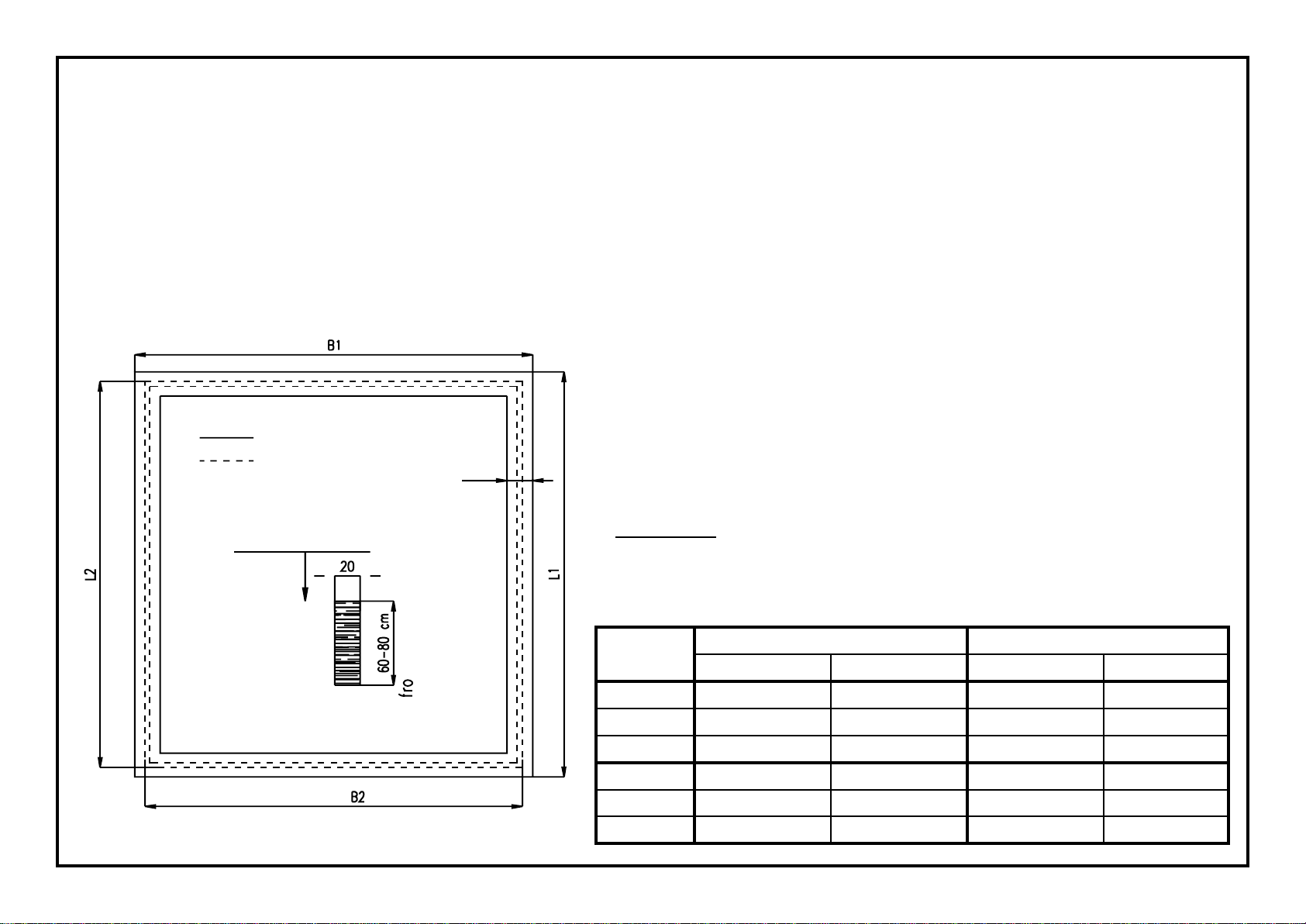
Placement of greenhouse:
If possible, choose a sunny location, avoiding the shadows of buildings and trees. For vegetables,
it is recommended to position your greenhouse in a north-south orientation if possible - for flowers
and potted plants, east-west.
For assembly, you will need the following tools:

3 - 5 mm 3 - 5 mm 6 - 8 mm
length
model
712 mm
(28.03 in)
768 mm
(30.24 in)
1030 mm
(40.55 in)
Riga S II 4 17
Riga S III 4 1 11
Riga S IV 4 1 14
3 - 5 mm 3 - 5 mm 6 - 8 mm
length
model
768 mm
(30.24 in)
1030 mm
(40.55 in)
1030 mm
(40.55 in)
Riga III 1411
Riga IV 1414
Riga V 1416
3
Additional notes for assembly:
Wedge seals (V23)
Pull them apart at the center.
After greenhouse is assembled, push the seal 3 - 5 mm between the soil
profile and the glazing on the inside of the greenhouse!
Important: Compress the seals when you install them as they contract in
cold weather
If forgotten, bolt heads can also be
inserted later in the plastic at the
bottom of the door frame and top or
bottom of curved aluminum extrusions.
You may also create your own insertion
point as needed with a 1/2" drill bit.
This will not compromise the integrity of
the structure.
Quantity of wedge seals
pos.4-2
pos.4-1
pos.3-3
pos.1-5-6
pos.2-1
pos.2-3.1
pos.2-3.1
pos.1-1
pos.1-9
pos.1-9
pos.1-5-4
pos.1-5-4
pos.1-5-6
pos.1-7
pos.1-6
pos.1-8
pos.3-2
IMPORTANT!
Quantity of cartons
basic construction
(gable/eaves)
curved center
profile
windows/
doors
glazing
Riga S/II/III/IV 1111
Riga III/IV/V 1111
Start with the box labeled "basic kit". Please open one box at a time to avoid confusing the parts.
Before you begin assembly of a section, check the parts list for that box and make sure all parts
are present. Parts lists are provided in every box. The boxes go through a quality check before
they are closed, thus missing parts are rare. Should any parts be missing please call Exaco
customer service at 877-760-8500 or [email protected].

4
Question: Does the greenhouse glazing need to be completely sealed?
We recommend that you seal the horizontal transitions where the glazing meets the
aluminum profiles with a neutral cure transparent silicone. (Shown in the diagram below by
dashed lines.) This will prevent water and dirt from entering the glazing slots.
Advantage: The greenhouse stays looking new as the seal prevents the formation of
algae and buildup of dirt/dust inside the glazing.
During some weather
conditions condensation can
occur within the hollow
chambers of the glazing. This
is because the glazing
chambers are not air tight. The
condensation is purely
aesthetic and cannot be
avoided.
The condensation/water vapor
will not damage the glazing,
even at freezing temperatures.
Warning: Use only neutral cure silicone, otherwise it may lead to stress cracks in plastic
glazing. This is the most common silicone sealant.
Neutral cure silicone is available in most hardware stores. We recommend Boss 399.
You can purchased Boss 399 directly from us, just call 1-877-760-8500.
Cleaning and care:
To wash the greenhouse use plenty of water, a soft car wash brush and a little mild dish
soap - Palmolive works well.
!!!Note: Important information for glazing!!!
When installing the polycarbonate glazing make sure the UV coated side faces out.
Loosen the edges of the protective film for installation. After the assembly is complete
pull it off immediately. Do not leave the film on for any period of time in the sunlight.
Several days of sunlight can burn the film firmly on the glazing. Markings on the film will
indicate the UV coating - most will be 2UV (coating on both sides).
Do not pull the film off right out of the box, otherwise you cannot tell which side has
the UV protection!
Suggestion: If you plan on disassembling and moving you should mark the UV side of
each panel before installation. A small circle in a lower corner with a permanent marker
will work well.

overview pos. description type II type III type IV
6.1foundation frame profile
gable 2
6.2 foundation frame profile
eaves
V26 foundation frame corner bracket
40/40/2 x 105
V27 mounting bracket
(rung/foundation frame)
S12
S1
hexagonal screw M6 x 12 +
nut M6
overview pos. description
Proles and accessories for foundation frame
Riga
: (V26/V27/S12/S1 as above)
number/length in mm/in
type III type IV type V
6.1foundation frame profile
gable
6.2 foundation frame profile
eaves
5
Foundation frame (optional accessory)
Proles and accessories for foundation frame
Riga S
:
Use paving stones or gravel under the horizontal sections as much as possible to prevent
the potential for the greenhouse to sag.
It is also very practical to install tile or stone flooring, this prevents the mud from splashing on
the greenhouse during heavy rain and makes work easier around the greenhouse, such as
mowing the lawn.
item no 9999 0078
item no 9999 0267
item no 9999 0124 + 9999 0128
ATTENTION: The Foundation Frame/Soil profile are assembled to check
for level and square. This is not final and will need to be disassembled.
Do not permanently attach corners or fill in the gable end trenches with
dirt. The side wall trenches can be partially filled with dirt.
Once this step has been completed go to Step 1 on page 10.
The optional Riga foundation frame is the easiest and the safest
foundation for a greenhouse. It requires no concrete.
ATTENTION: When using the Riga foundation frame attach it to the soil
profile before these steps (see pages 5, 6)
The foundation frame hooks into the soil profile and the corners are
bolted together with a corner angle (V26). (See page 6). Use the
supplied self tapping screws to firmly attach the soil profile to the
foundation frame.
Setting up the foundation frame
Dig a small ditch 4-5 inches deep in the dimensions of the foundation
frame.
number/length in mm/inches
86
2199 mm
9/16" 286
2199 mm
9/16" 286
2199 mm
9/16"
280
2033 mm
1/16" 2121
3091 mm
11/16" 2163
4149 mm
3/8"
44
105 mm
1/8" 44
105 mm
1/8" 44
105 mm
1/8"
105
135 mm
5/16" 105
135 mm
5/16" 105
135 mm
5/16"
20
2020
2111
2835 mm
5/8" 2111
2835 mm
5/8" 2111
2835 mm
5/8"
2121
3091 mm
11/16" 2163
4149 mm
3/8" 2205
5207 mm
"
outside of
greenhouse
inside of
greenhouse

6
Note: The founda-
tion frame profiles
are shorter than
soil profiles
Attaching the greenhouse to your own foundation or anchoring system
We recommend that you use anchor bolts to secure the soil profile to your foundation.
The anchor bolts are not included.
side profile/
door frame
mounting bracket
- offset - (V15)
bolt M6 x 12 (S12)
+ nut M6 (S1)
soil profil
Rotate the foundation frame profile into the soil
profile. Make sure it is centered in the soil profile.
Note: The foundation frame profiles are shorter
than soil profiles
To stabilize the
greenhouse, use the
mounting bracket (V27)
with bolts M6 x 12 (S12)
Bolt the (V27) to the
foundation frame and the
side curves or door
frames.
Use the supplied self
tapping screws to firmly
attach the soil profile to
the foundation frame.
In the foundation frame corners use two M6 x
12 bolts (S12) and one corner bracket (V26)
Fasten them with two M6 nuts (S1).
Assembly foundation frame
Self-tapping screw placement

model foundation
W1L1
greenhouse
W2 L2
Riga S II 249cm / 98 1/16"
Riga S III
Riga S IV
Riga III
Riga IV
Riga V
7
W1
W2
If you have not purchased a foundation frame secure the greenhouse by
means of a strip or perimeter foundation. Create the foundation in
accordance with the specified dimensions below.
A stone/cement base is not required. The greenhouse can be
placed directly on the ground but it must be anchored securely.
You may also place the greenhouse on a full slab foundation - consider
texture and drainage.
Please make sure that the foundation is level in all directions.
Once assembled, anchor the greenhouse with the included mounting
brackets (V15)
Screws and anchors are not included.
Suggestion: Assemble the lower frame (soil profiles 1.1/2.1, soil profile
corner V9) of the greenhouse to use as a template to create a stone or
concrete foundation. Make sure the corners are square. This will
prevent any errors in measurement.
4 1/8
Foundation plan Riga S/Riga
Construction with a perimeter or strip foundation
249cm / 98 1/16"
249cm / 98 1/16"
312cm.../12213/16"
312cm./.12213/16"
312cm / 12213/16"
232cm./ 91 5/16"
338cm../133 1/16"
443cm./174 7/16"
338cm../133 1/16"
443cm./174 7/16"
549cm /216 1/8"
233cm / 91 3/4"
233cm / 91 3/4"
233cm / 91 3/4"
296cm ./116 9/16"
296cm.../116 9/16"
296cm ./116 9/16"
216cm /851/16"
322cm /1263/4"
427cm /1681/8"
322cm /1263/4"
427cm /1681/8"
533cm/ 20913/16"
Greenhouse on a Stem Wall
(Requires optional door extension/drop door kit)
You must have a door extension kit to place the Riga greenhouse
on a stem/knee wall. The wall must be 20" high and the rough
opening for the front door should be 33" wide.
Use the greenhouse exterior dimensions for your wall exterior
dimensions - this will ensure your doors will open fully and connect
with your door catch. Please be sure the thickness of your wall
allows for secure anchoring and meets local building standards.
exterior of greenhouse
exterior edge of foundation
Upper edge of ground
frost-free
ground
EEs

overview pos. description
number/length in mm
Riga S Riga
II III IV III IV V
2.1soil profile/eave
2.3 Side curve
3.2 cross bar/roof window
3.3 ridge profile
3.4 angle stabilization
overview pos. description
number/length in [in]
Riga S Riga
II III IV III IV V
1.1soil profile/gable
1.5.4 Edge curve left
1.5.6 Edge curve right
1.6 door frame left
with slant
1.7 door frame right
with slant and holes
1.8 door frame top
1.8 cross bar
in the side door without
1.9 cross bar left and right
8
Main box Contents - basic kit Riga S/Riga
Please check contents list to make sure all items are there
Proles for both gables:
Proles for eaves:
2
88 1/8 "
2238 mm 288 1/8 "
2238 mm 288 1/8 "
2238 mm 21131/8 "
2874 mm 21131/8 "
2874 mm 21131/8 "
2874 mm
2
222
22
2
222
22
73 7/8 "
1876 mm
273 7/8 "
1876 mm
273 7/8 "
1876 mm
2
73 7/8 "
1876 mm
273 7/8 "
1876 mm
273 7/8 "
1876 mm
2
811/16 "
2059 mm
2811/16 "
2059 mm
2811/16 "
2059 mm
2
811/16 "
2059 mm
2811/16 "
2059 mm
2811/16 "
2059 mm
2
2913/16"
758 mm
22913/16"
758 mm
22913/16"
758 mm
22913/16"
758 mm
22913/16"
758 mm
22913/16"
758 mm
2
2913/16"
758 mm
12913/16"
758 mm
12913/16"
758 mm
12913/16"
758 mm
12913/16"
758 mm
12913/16"
758 mm
1
275/8 "
702 mm
4702 mm
4275/8 "
702 mm
4275/8 "
702 mm
440 3/16"
1020 mm
440 3/16"
1020 mm
440 3/16"
1020 mm
4
819/16"
2072 mm
21231/4"
3130 mm
216414/16
4188 mm
21231/4"
3130 mm
216414/16"
4188 mm
22069/16"
5246 mm
2
4
266
48
40 3/16"
1020 mm
140 3/16"
1020 mm
140 3/16"
1020 mm
240 3/16"
1020 mm
140 3/16"
1020 mm
240 3/16"
1020 mm
4
84 1/8"
2137 mm
112513/16"
3195 mm
11677/16"
4253 mm
112513/16"
3195 mm
11677/16"
4253 mm
12091/8"
5311 mm
1
8213/16"
2014 mm
41241/2"
3162 mm
41661/8"
4220 mm
41241/2"
3162 mm
41661/8"
4220 mm
420713/16"
5278 mm
4

overview pos. description/
item number
num-
ber
Riga S
num-
ber
Riga
V9 Soil profile corner 4 4
V5 connecting plate Edge Clamp/Door Frame 4 4
V10
connecting plate 90 x 35 mm
For mounting
cross bar/rear 2 2
V11 endplate ridge/gutter 2 2
V4 connecting plate for cross bar/roof window
II = 2
III = 2
IV= 4
III = 2
IV = 4
V = 8
V12corner
30/30/2/15 mm
soil profile
screw the corner from inside
4 4
S21blind plug Ø10 mm To plug Edge profile hole to
attach cross bar 4 4
V14 door hose section 760 mm lg. door threshold seal 1 1
V23 wedge seal 3 - 5 mm sealing the soil profile insid
See
table
below !
See
table
below!
S9 screw pan head
4,2 x 13
door frame-soil profile
cover plate/corner (V12) 38* 38*
S13 4,8 x 45 gable 6 6
S5/
S1
hexagonal screw M6 x
16 + nut
bolts for construction of
greenhouse
II = 40*
III = 40*
IV = 44*
III = 40*
IV = 44*
V = 48*
V15mounting bracket - offset
74 x 30 x 33 mm
for the attachment of the
greenhouse to a foundation
made by customer (not
with foundation frame)
1010
S32 washer A6,4 door frames, roof and
side profiles 20 20
V = 24
V1mounting corner bracket
inside
2x left
2x right
2x left.
2x right
9
Accessories bag basic kit Riga S/Riga
item no 9999 0003
item no 9999 0028
item no 9999 0030
item no 9999 0075
item no 9999 0031
item no 9999 0072
item no 9999 0097
item no 9999 0181
item no 9999 0119
item no 9999 0144
item no 9999 0207
item no 9999 0183 + 9999 0128
item no 9999 0150
item no 9999 0173
item no 9999 00074
screw, pan head

Riga S Riga
730 x 728 1048 x 728
10
Assembly procedure gable
ATTENTION! When using a foundation frame attach it to soil profile in advance (see pages 5, 6)
soil profile (pos.1.1
door frame right (pos.1.7)
door frame left (pos.1.6)
soil profile corner (V9)
step 1
glazing
glazing
Attach with screw pan head 4,2 x 13 (S9)
after the door is mounted and aligned
cross bar (pos.1.9) cross bar (pos.1.9)
view from inside
screw pan head 4,2 x 13 (S9)
connecting plate (V5)
screw M6 x 16 (S5)
with nut M6 (S1)
glazing
door frame
top
(pos.1.8)
glazing
to step 1:
Items needed:
Pos 1.6 (Door frame left)
Pos 1.7 (Door frame right with 8 holes)
Pos 1.1 (Soil Profile)
Soil Profile Corner (V9)
Slide pos 1.6 and pos 1.7 up to the
small holes in the middle of pos 1.1(soil
profile). The chamfered edge must be
facing to the outside. Then attach the
soil profile corner (V9) to the ends of the
soil profile.
step 2 to step 2:
Now you need the small side glazing.
Slide the side glazing into the door
frames and soil profile.
The dimensions are listed in the
diagram.
Note: After the door is mounted and
aligned attach pos 1.6 and pos 1.7 with
pan head screw 4,2 x 13 (S9).
step 3 to step 3:
Now insert the cross bar (pos.
1.9) onto the top of the glazing.
step 4 to step 4:
Items needed:
Two Connecting Plates (V5)
Pos 1.8 (Cross Bar-door frame top)
Four Hex Screws M6 x 16 (S5)
Slide one hex screw M6 x 16 (S5) into
the vertical door frames(pos1.6/1.7)
and two in the crossbar(pos 1.8)
Attach the crossbar to the door frames
with the connecting plate (V5).
Insert the curved glazing into the door
frames and cross bar (pos 1.9)
view from inside

11
glazing
Edge curve right - (pos.1.5.6)
Edge curve left - (pos.1.5.4)
Edge curve connects to the soil profile corner (V9)
The rear gable is assembled in the same way!!!
glazing
Only rear gable!
cross bar
(Pos.1.8)
step 5 to step 5:
The square peg in the soil profile
corner (V9) is plugged into the bottom
of the Edge curve (pos.1.5.4/1.5.6).
The small triangular glazing is
positioned in the door frame top (pos
1.8)
The Edge curve (pos.1.5.4/1.5.6) is
attached to the door frame using the
connecting plate (V5), installed in step
4, and 2 screws pan head 4,2 x 13
(S9). Insert 2 bolts into the channel
of each edge curve for attaching
lateral support later.
All fasteners should be hand tight.
- See also step 4! -
step 6: to step 6:
The cross bars (pos.1.9) are
mounted horizontally with the
pan head screw 4,8 x 45 (S13).
step 7:
view from outside
to step 7:
Slide the upright profiles (pos 1.6/1.7) into
the soil profile.
Insert the (787 x 728 mm) glazing between
the upright profiles (pos 1.6/1.7)
Insert one M6 x 16 (S5) into each upright
profile (pos 1.6/1.7)
Insert four M6 x 16 (S5) into the cross bar
(pos 1.8)
Insert one M6 x 16 (S5) into each cross bar
(pos 1.9)
Connect the upright profiles (pos 1.6/1.7) to
the cross bars (1.8/1.9) with connecting
plates (V10)
Attach the edge curve left/right (pos.1.5.4/
1.5.6) to the cross bars (1.9) with the pan
head screw 4,8 x 45 (S13). Insert 2 bolts
into the channel of each edge curve for
attaching lateral support later.
view from outside
1x
M6x16
4x
M6x16
1x
M6x16
connecting
plate (V10)
Assembly procedure gable
ATTENTION! When using a foundation frame attach it to soil profile in advance (see pages 5, 6)

overview pos. description num-
ber length in mm
2541mm / 213/16"
4.1 roof window side prole
4.2 roof window top/bottom profil 2953mm / 371/2"
overview pos. description/item number num-
ber length in mm
*V25 T-seal 2
1
641mm / 251/4 "
1052mm / 417/16"
V13 corner with grub screw, internal hex and at point 4
V21allen key 1
S12/
S1
hexagonal screw M6 x 12
nut M6 3
V24 corner bracket/roof window 4
12
Proles for roof windows (per roof window)
Content accessories bag roof window (per roof window)
*Note: The seal is bundled in one strand for all doors and windows, please cut accordingly.
Gasket Notes:
T-seal (V25) is for all doors and
windows (total: 15 meters/49 feet)
long flap goes towards exterior
Attention! The T-seal (V25) is only inserted on
three sides of the roof window. The top side
slides into the roof beam so no seal is required.
In the door threshold, the hose section
(V14) is pressed into the soil profile.
This prevents dirt from getting into the
soil profile.
Attention! In the lower door
press the seal into the profile
first then install the rectangular
tube.
item no 9999 0032
item no 9999 0070
item no 9999 0056
item no 9999 0128
item no 9999 0005
item no 9999 0124
*
Roof Windows

13
Assembly roof window
corner with grub
screw (V13)
Side window profile (pos. 4.1)
Top window profile (pos.4.2)
(This profile requires no T-seal)
Bottom window profile (pos. 4.2
corner bracket/roof window (V24)
automatic roof window opener
Mounting roof window
wrong!!! right
Please push the roof window from the gable
end into the ridge profile and slide it into
position.
Install the automatic opener mount into the
crossbar.
Attach the roof window side profiles to the bottom roof window
profile using the corner brackets and the metal corners with grub
screws.
Insert the roof window glazing into the side/bottom profiles you
have assembled.
Attach the top roof window profile, tighten all grub screws and
insert T seal on the three lower sides of the roof window. Angle
cut the ends of the T seal where they meet at the corners.
Seal with silicone to prevent leaks!
Apply silicone to the short ends of the window extrusions
before inserting black corner bracket (V24). Once the window
is assembled, use silicone to seal where the polycarbonate
meets the aluminum framing of the roof window. See page 14
for details.
Attention: In the bottom cross profile insert two hex screws M6 x
12 (S12) for the window opener!
sash lock (V28) may
be attached here with
screw countersunk
head 3,5 x 22 (S19)
scews.

14
Sealing the roof window area
Apply silicone to black
corner connectors where
they meet the profiles.
Apply silicone where the
polycarbonate meets the
aluminum frame. ( ).
cross-section of
the flat seal
length: 2,3 m
pos. 3.2
pos. 4.1
The flat seal is inserted as the sketch above.
Attention: Do not cut the flat seal in the corners! Run it in one continuous strip.
Please seal all connections of the roof window with silicone: Corner connector to
side and bottom profile and glazing to side and bottom profiles. → see sketch.
Seal with silicone around frame ( )!
side curve
pos. 2.3
cross bar
pos. 3.2 window profile
pos. 4.1 und 4.2
pos. 4.1
▲
▲
▲
▲
▲
▲
Also use silicone to seal between the crossbar (pos 3.2 )
and the curves of the greenhouse
▲
▲
________

15
Automatic Window Opener
When the temperature decreases and the window is no longer to be opened, or when a source of
heat is used in the greenhouse:
1. Unscrew the cylinder from the cylinder housing. The cylinder is now hanging from the cotter pin
and cannot open the window. The cylinder can be left hanging in this position over the winter.
2. Use a sash lock to lock the window shut for the winter so it cannot blow open.
Adjustment:
Winter-usage:
Auto Opener Installation
1. Check whether the greenhouse window can open and close freely and unhindered.
2. Install the opener with the mounting plate (4) in the center of the lower roof window profile (pos 4.2)
3. Secure the cylinder by lining up the hole in the piston with the upper hole in the T-coupling, then
insert the cotter pin.
4. Install the mounting plate (5) in the center of the cross bar(pos 3.2) using the middle hole in the
mounting plate(5)
5. Attach the opener frame (1) to the mounting plate (5). Open the roof window until the threads of
the piston (2) engage the threads of the opener frame (1). Thread the piston (2) half way into the
threads in the opener frame (1).
Let the opener acclimate to the greenhouse for 3-4 hours before you make adjustments.
For earlier engagement and a larger opening, turn the cylinder clockwise. For a delayed engagement
and a smaller opening turn the cylinder counter clockwise. Make sure you don’t back it out too far.
For opening engagement advance/delay one full turn is about 1 degree Fahrenheit. Please keep in
mind that greenhouse temperatures can vary and windows can have different opening tolerances.
1
2
3
4
5
1opener frame
2 pressure cylinder
3 cotter pin
4 mounting plate window profile
5 mounting plate cross bar
3
Required Maintenance:
Every year, check to make sure the piston shaft and cylinder threads are greased and move freely. A
dab of light oil such as WD40 or olive oil on the piston shaft and the cylinder threads will be sufficient.
Failure to do so could render your opener inoperable.

In the correct position, the opener is sitting parallel
to the window, which means that it will not
demand a lot of pressure from the cylinder when
the opening starts. Before fitting a new cylinder to
the openers, you must check that the window can
open freely right from the start. If not you must
change the position of the aluminum profiles.
Riga Greenhouse Window Auto Opener Correct Installation
16

Roof Vent Recommendation for High Wind Areas
If you get strong wind gusts, we recommend protecting your roof vents and openers with restraint
cables.Roof vent restraints can be purchased from Exaco Trading (US distributor of Rigas) or can be
made, they are not a standard part from the Riga manufacturer.
Two restraints are used for each window; one on each side of the window. Install each loop between
two flat washers on screws inserted into the channel. Position the restraint as illustrated and adjust as
needed to avoid interference from the crossbar as the window is raised and lowered.
You can make your own restraints from 1/16 “ stainless wire rope,stranded 7x19 for maximum flexibility.
Overall length should be about 16”. When installed near the crossbar, they will limit the window
opening to less than the safe extents of the hinge and window opener, but greater than the maximum
thermal extent of the opener. More important than the exact length of the restraint is a close length
match for each window’s pair. If you are not equipped to swage the binding sleeves you can use wire
rope clamps.
*Only need 1 washer on top of the cable
17

overview pos. description num-
ber length in mm
5.3.1 door profile bottom1700mm/279/16"
with hole for sash lock 1
with hinge hole 1
with transverse hole 1
5.6 door profile left
5.7 door profile right
5.9 door profile top
5.8 square tube with transverse hole 1
overview pos. description num-
ber length in mm
V51metal hinge, black 2
V28 sash lock 1
V29 QR-stopper 30 x 30 x 1,5-2 2
* V25 T-seal 2
2
S18 screw countersunk head 4,8 x 25
(hinges) 8
S17 screw countersunk head 4,2 x 45
(doors) 4
S19 screw countersunk head 3,5 x 22
(sash lock) 2
S6 pan head screw 3,5 x 38 (square tube) 2
V32 glazing block 30 x 10 x 4 2
V30/
V31corner bracket door profil 4
18
Proles for divided revolving door - bottom -
*Note: The seal is bundled in one strand for all doors and windows, please cut accordingly.
Content accessories bag divided revolving door - bottom -
item no 9999 0358
item no 9999 0023
item no 9999 0032
item no 9999 0163
item no 9999 0160
item no 9999 0152
item no 9999 0138
left - item no 9999 0009
right - item no 9999 0011
item no 9999 0099
*
*
692mm/271/4"
692mm/271/4"
700mm/279/16"
740mm/291/8"
710mm/2715/16"
744mm/295/16"

19
QR-stopper
(V29)
corner bracket door profil
(V30/V31)
Lay the profiles out like the diagram below (possibly on cardboard or something similar).
First: Insert T seal in
Door profile top (pos
5.8)
Second: Attach
square tube to door
profile to (pos 5.8)
with pan head screw
3,5 x 38 (S6).
Assembly - divided revolving door - bottom -
view from outside
square tube (pos. 5.8)
door profile top (pos. 5.9
sash lock
(V28) with
screw
countersunk
head 3,5 x 22
(S19) scews.
door profile right (pos. 5.7
door profile left (pos. 5.6
glazing block (V32)
screw counter-sunk head
4,2 x 45 (S17)
door profile bottom (pos. 5.3.1
*Note: The seal is bundled in one strand for all doors and windows, please cut accordingly.
This manual suits for next models
1
Table of contents
Other HOKLARTHERM Greenhouse Kit manuals
Popular Greenhouse Kit manuals by other brands

Outsunny
Outsunny 845-421V03 Assembly & instruction manual

Little Cottage
Little Cottage Colonial Gable Greenhouse Assembly & instruction manual

GrowSpan
GrowSpan PB01750R6 Assembly instructions

GrowSpan
GrowSpan Gothic Pro manual

Janssens
Janssens Victorian Vi-34 Assembly instructions

Vitavia
Vitavia Hera 4500 Assembly instructions