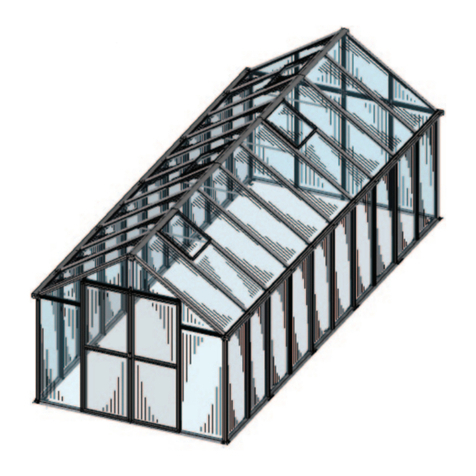
HOKLARTHERM Livingten User manual

Assembly Instructions – Livingten
Greenhouse
The secure assembly of your Livingten greenhouse is simple if you follow our assembly
instructions and our recommendations exactly. Please read through carefully before starting
assembly!
1. Foundation frame incl. attached soil profile
First, attach the soil profiles to the foundation frame profiles, which can easily be slid on or
pivoted/twisted in from the side. The exact length-wise position does not need to be considered
at this point.
Start with the short profiles (gables) – the front/back of the greenhouse – these already have
plastic corner connectors on both sides. The plastic corner connectors serve for controlled
drainage of the soil profiles. For example, in the case of moisture accumulation the ISO safety
glass panes do not "stand in water" and they connect the corners of the greenhouse to the
foundation.
On one short profile, attach the two long profiles with two M6 x 12 screws on each side.
Before you can complete the whole foundation, you have to insert the plastic corner connectors.
Only then, you can attach the other short profile with the U-shaped foundation.
Now, align the plastic corner connectors of the short soil profile perfectly over the sleeve (dia.
30mm) of the foundation frame connector. Then insert the long soil profiles to fully connect the
whole foundation frame. Now you can screw it together.
{picture}
The foundation frame with the greenhouse soil profile is now complete and can be placed and
positioned on the concrete slab or possibly perimeter foundation. First, align one long side
exactly the way you want it. Insert a plastic pipe (30/20 x 100 mm) into the pipe sleeve of one
corner connector (of this long side). This pipe will function as a drilling aid for the 20 mm
diameter hole. Now, drill a 100mm deep hole into the concrete through the plastic pipe (drilling
aid). After removing the drilling dust and the drilling aid, insert a new plastic pipe (30/20 x 400
mm) into the sleeve of the corner connector.
Then insert or drive a stainless steel dowel (diameter 20 mm) into the plastic pipe. It should
reach the end of the hole so that it anchors the frame absolutely securely to the concrete and
provides the greenhouse perfect alignment.
Now, in order to get a greenhouse with perfect right angles, the diagonals have to be
measured exactly. Position the greenhouse so that it’s perfectly perpendicular (diagonals

measure the exact same distance) and continue with the other holes and “dowels” as you did
with the first one.
Now check if the foundation frame lies exactly horizontally on the concrete. Otherwise, please
"underpin" the foundation frame with suitable material so that everything is perfectly level.
The first and most important construction phase is now finished!! – As with all things, a good,
precisely built foundation is the basis for success!
{picture}
2. Mounting the greenhouse corner profiles –
The upright corner profiles are attached to the protruding pipe ends (PVC and stainless steel
dowel) so that the small 5 mm holes (in the middle) are positioned on the outside toward the
long sides (they will be used to attach the gutter downpipes). The profiles are pushed into the
plastic corner connectors – please make sure they go all the way to the bottom, they should
not get caught on the edge.
{picture}
3. Mounting the eaves profiles
This profile is inserted from the top into the upright corner profiles using already mounted short
pipe ends. Also here, please make sure that the profile fully rests on the corner profile.
{picture}
4. Mounting the gable crossbeams
This profile is connected to the eaves profile by mounting the stainless steel corner connectors.
The bevel of these connectors must show 30° towards the front sides. Later, the roof edge bars
will be attached here. There are right and left versions!
{picture}
5. Inserting the glazing on all sides
Now the complete greenhouse contour – up to the height of the eaves – is built up.
The construction is still a bit wobbly, but already firm enough that all the side ISO safety glass
panes can be set all around. Since all the panes are the same size, there can be no confusion
in the choice of panes. Insert the top of the panes as far up into the eaves profile as you can so
that they slide over the edge of the soil profile and fit into that channel.

Please check before inserting the panes if possibly protruding pane edge seals are
sticking out and if so remove them – a precise glass dimension is necessary. This
applies to all panes!
Please proceed in the following order: Two panes at a corner profile (each side of the
corner). Push them all the way up against the corner profile. This already stabilizes the
construction in all directions.
{picture}
Then set all other panes (only the panes, not the bars). Insert panes as far up into the eaves
profile so that it slides over the edge of the soil profile into the groove.
– Please ensure that the panes stand on the already factory-glued glazing blocks at the bottom!
Since the eave profile sags a little in the middle, lift the profile slightly in order to insert the glass
panels properly.
{picture}
In order to be able to insert all the glass panels, slide them as far to the side as possible (some
to the left, some to the right). Push together tightly (without bars) so you have a gap in the
middle.
This gap width must be checked! According to the following table:
Greenhouse length
Gap size
5 panes
62 – 65 mm
6 panes
77 - 80 mm
7 panes
92 – 95 mm
Why? The ISO safety glass panes have production tolerances that must be taken into account.
–
Should the gap exceed the given upper value, glazing blocks must be inserted into the
construction. Start with both top and bottom in the upright corner profile. If this is not
sufficient, also glue glazing blocks into one or the other bar in the same way, so that the
difference is compensated for and the given gap dimension is achieved. This results in
the statically necessary "pane effect" - The construction should no longer be able to be
moved. –absolutely safe e.g., against wind pressure and suction. -

The glazing blocks have a thickness of 1 mm and are included in the accessories. Ideally, only
glue one block into the corner profile – each top and bottom – or into a bar on both sides each 1
block, so that a sufficiently uniform and even glass installation is achieved.
The above procedure is rare, but we cannot eliminate the smallest deviations in the glass
production.
In the worst case (which has never happened so far), the panes are too wide and the gap falls
below the lower dimension. In this case, possibly 4 panes would have to be exchanged for
smaller ones with adjusted widths – 2 x side panes 2 x roof panes. In such cases, please
contact our service, as there may also be other solutions here.
Now, insert all the upright bars by simply sliding them between glass panels.
{picture}
Insertion of the so-called repair bar/strut - This strut is inserted at the end, when all other
bars have been inserted. Install it from the inside of the greenhouse into the gap to close it. - If
there is still space between the glass and the strut, this gap can/should also be closed with a
suitable glazing block - max. 2 mm - at the top and bottom. Please secure them with silicone
against slipping.
From the outside, the cover shell is then screwed on. - flat-head screw 4.2 x 9.5
{picture}
A similar procedure is used in the rear gable.
First, the center upright support bar to the ridge is mounted and fixed in the intended position
using a M6 x 50 mm screw, large washer and cap nut on the soil profile. Mount it exactly in the
middle but movable. At the gable crossbeam use a flat-head screw 5.5 x 70 and large washer in
the given position. Check the vertical alignment with a level! This profile will later support the
greenhouse ridge.
The outer glass panes are already inserted in the corner profile, the middle panes are now slid
into the upright center profile.
In the remaining gaps of each 15 mm, two upright "repair-static struts" (left and right version)
are inserted from the inside of the greenhouse. Push it between the panes and mount them both
at the bottom in the soil profile and at the top in the gable crossbeam with a M6 x 55 screw,
large washer and cap nut. From the outside, a long cover shell - and one with a 30° miter cut 30
° - left and right version - is then screwed on. - The short cover shells are used only during
the upper gable glazing!

Note: all bolt heads and connectors can be inserted through the insertion points in the
channels. Slots approx. 11.5 x 50 mm long or holes diameter 11.5 mm - As a rule of
thumb, these possibilities are provided approx. 150mm from the respective profile end.
{picture}
The door gable is mounted in a similar way with the long upright center profile missing
here (because of the door). Here the door gable crossbar has a factory-installed reinforcement
profile (track) for the sliding door and therefore differs from the rear wall version.
In the middle of the door passage, a short version of the support bar is mounted and screwed
on. The greenhouse ridge support is also placed/inserted here.
Sketches
6. Roofing ceremony - Placement of the ridge profile
The ridge is placed on the center upright bar of the back gable and front gable by using plastic
pins that are already factory-installed.
The necessary roof bar "connectors" are already screwed onto the greenhouse ridge in the
correct position, specifying the position/distance of the struts.
{picture}
7. Inserting the roof profiles
Now all roof profiles can be inserted. The positions are determined by the "connectors" already
pre-mounted in the roof ridge profile. The roof profiles should be first inserted into the ridge
profile and then slid into position on the eaves profile. Possibly push the eaves profile slightly
outwards so that it "snaps in".
The roof profiles all have holes for inserting the statically necessary tension braces –
- 2 x flat 40x4 - - 2.000 mm long. – each as a pair –
This pair of tension braces is installed in the greenhouse L 5 = 5 panes in the 2nd or 3rd pair
of roof profiles. Mount with M6 x 55 screws with U-washers and cap nuts. A M6 x 55 screw is
also inserted in the middle – use plastic bushing 10/6 x 40 mm washer and cap nut as a spacer.

For a greenhouse length – L 6 and L 7 – 2 pairs of tension braces are installed in each
second field --from the greenhouse gable point of view -
Attention – the tension braces are installed slightly "tense" and must be installed before
the roof glazing is installed, as there is still the possibility to push the greenhouse ridge
slightly upwards so that the last screw can easily be inserted or connected/screwed
together with the tension braces.
{picture}
8. Glazing of the gable peaks
Now it is appropriate to mount the upper glass panels on the gables. Two safe step ladders and
4 hands are required to adjust the triangular panes from the top into the bars at a height of
approx. 2.3 m and screw them in the middle with the cover shells – short version – left/right.
{picture}
9. Mounting of the roof edge bars
The roof edge bar is first inserted into the ridge profile, onto the set panes, and then carefully
inserted into the eaves profile, where it is mounted to the eaves profile just like before.
Attention two screws have to be inserted into the channel of the eaves profile, one M 6 x 55
and one screw M6 x 12, in order to make a connection with the "repair-static strut" M6 x 55 the
stainless steel corner connector. In this area, please check again the alignment of the profiles
with a level and tighten all screws. Check at the corner connector that the eaves edge and
gable crossbar are tightly pushed together!!
{picture}
10. Inserting the roof glazing
For additional sealing, silicone plug-in gaskets, length 820 mm (already pre-cut) are used on
the eaves profiles, which later touches the bottom of the ISO safety glass panes of the roof.
They provide additional insulation and separation of the condensation water channel located
on the inside.
{picture}
Now the ISO safety glass panes can be slid in from the side of the greenhouse.

Note: The gutter profile is only inserted or clipped in from the side after the glazing has been
completed. Otherwise, the insertion of the glazing would not be possible. If the structural
situation does not allow the glazing to be inserted this way, the panes can of course also be
mounted sideways, which is much more cumbersome. - Please ask us in advance for the
procedure in such cases!! - In these cases, a so-called Repair-roof strut - with a cover shell
may be necessary.
Practically, 6 hands are needed: 4 hands to slide the panes - weight approx. 32 kg - from in
front of the sidewalls into the roof bars and 2 hands inside the greenhouse to guide the pane
into the ridge profile at the top! Make sure that the silicone plug-in gasket remains in the
intended position! Otherwise, the process must be repeated.
Attention! These silicone gaskets must be put on before inserting the glazing!! Later
insertion is not possible without disassembly of the panes!!!!
If the gap between the bars is too narrow, please move the bar to the required position!
The exact position of the bars can be corrected later by positioning the strut connections in the
eaves area!
During the pane assembly, the "glass brakes" (a manifold tilted sheet metal piece) are inserted
into the eaves profile. The panes must be pushed up into the ridge so far that this sheet can be
inserted into the intended eaves profile slot. This ensures a secure fit of the roof panes.
After complete assembly and pressing in of the sealing profiles, the beginning/end of the glass
should be sealed with silicone to ensure that the edge of the ISO safety glass panes does not sit
in water.
Since all seals are pressed in from the inside, the final position of the glazing is only reached
then. - Due to the seals, the glazing is shifted upwards by approx. 2 mm.
{picture}
11.Assembly of the gutter profile and the downpipes
{picture}
-
12. Assembly of the corner and end caps - Form and edge sheets.
{picture}
Note: Please inject silicone into the profile contours of the plastic end caps to create a seal both
in the gutters and to the ridge.
13.Final work - pushing in the seals.

Table of contents
Other HOKLARTHERM Greenhouse Kit manuals
Popular Greenhouse Kit manuals by other brands

Growers SOLUTION
Growers SOLUTION Quonset instruction manual

Black Orchid
Black Orchid Hydro-Box Assembly & instruction manual

Sproutwell
Sproutwell GRANGE-3,3000 Assembly instructions

Halls
Halls 42 2 Assembly

Flower House
Flower House StarterHouse manual

Palram
Palram Plant Inn-Clear Glazing Assembly instructions

Mercia Garden Products
Mercia Garden Products 04MINIG-V1 General instructions

Palram
Palram Americana manual

ClearSpan
ClearSpan 104903 Assembly instructions

One Stop Gardens
One Stop Gardens 97439 Setup and maintenance instructions

Outsunny
Outsunny 845-243 Assembly & instruction manual

GrainPro
GrainPro MA4040RAD0914-10 instruction manual