Growers SOLUTION DAKOTA User manual

Page 1 of 4
GrowersSolution.com 931.528.3390
DAKOTA GREENHOUSE INSTALLATION
!!!! CAUTION: Tubing ends may be sharp!!!
Read directions completely before beginning assembly. We recommend that you visit The Learning Center at
www.growerslearning.com, click on How to Assemble under categories. In this section you will find video tutorials
to assist you with the assembly of your new greenhouse. If you have ANY questions please give us a call at
866-928-3390.
Step 1 –Ground Stakes
Square the corner stakes with each other. Take all
measurements on the outer edge of pipe.
Drive Corner stakes 18 inches in ground and then drive rest of
stakes 4 ft. centers (Fig 1.1).
NOTE: Use a large bolt and washer, or 2 x 4 on top of stakes to drive
them into the ground.
Fig 1.1 Ground Stakes
Step 2 –Bow Assembly
Place bow sections on flat ground.
Slide sections together (Fig 2.1), and secure at joints with self-
tapping screws that are provided (Fig 2.2).
Measure up each end of bow 6 inches and make a reference
mark. The mark is how far the bow slides into the ground stake.
Each bow is 7 pieces total; 3 angular, 2 side wall uprights, and 2
gable pieces.
Fig. 2.1
Fig 2.2 Bow Assembly

Page 2 of 4
Step 3 –Bow Installation
After bows have been assembled, raise upright and place ends in
ground stakes (Fig 3.1) and attach with TEK screws.
Fig 3.1 Bow Installation
Step 4 –Purlins
The straight purlin pipe sections connect together with self-
tapping TEK screw. The assembled purlin is attached to the first
and last bow (Fig 4.1) using a 2-hole strap (Fig 4.3). The purlin
clamps are used on the remaining bows (Fig 4.4). Trim extra
pipe off. The Dakota House has 3 runs of purlin. One at the
center of bow inside of the house (Fig 4.1), one on each sidewall
at top of upright inside of the house (Fig 4.2). Make sure to view
illustrations.
NOTE: The TEK screw is drilled through the 2-hole strap in Fig 4.3. This
secures the end of purlin to greenhouse.
Fig 4.1 Center of Bow
Fig 4.2 Sidewalls
Fig 4.3 2-Hole Strap Fig 4.4 Purlin Clamp
Step 5 –Base Boards
Attach base boards (2 x 6 pressure-treated recommended) on
the bottom of the sidewall outside of house with supplied 2-hole
pipe straps.
IF you have roll-up sides you will need to install a head board
also. This is installed anywhere from 3 feet all the way up to the
bend at about 6 feet on each side. Install this with the supplied
2-hole straps.
NOTE: You must attach 2 hole strap to ground stake using self-tapping
screws also use wood screws (not included) to attach to your
timber.
Fig 5.1 Base Board

Page 3 of 4
Step 6 –End Walls
NOTE: End walls are set up for a 36 inch storm door (not provided).
The rough in for a 36 inch storm door is normally 36 ½ inches.
On front end-wall, measure to find the center of the house.
From the center, mark 18 inches to the left and right of that
point. This gives you the door frame size.
Drive the 1 inch ground stake in at each of these two points (will
be approximately 36 inches apart). This is where your storm
door will be. Rough in for a 36 inch storm door is normally 36 ½
inches.
Measure the distance between the base of these ground stakes
and peak of the bow where they will be connecting.
Cut your square uprights (if needed) to meet these
measurements, slide square uprights over the ground stakes
with pre-drilled side at the top.
Attach brace bands over the bow and into the square uprights
(see Fig. 6.1).
Insert bolts through brace bands and square upright (Tighten
completely after door is installed).
Place one self-tapping TEK screw through the brace band
securing it to the inside of the bow.
Using TEK screws, install header with corner braces and header
tie.
The installation of the rear end-wall is the same. However,
header & upright spacing can be adjusted to accommodate a fan
or vent if you choose to install one.
Fig 6.1
Fig 6.2
Fig 6.3
Step 7 –Wire Lock
NOTE: Not all houses use wire lock. Some use batten tape and staples.
Attach the Wire Lock Channel on the top of first bow and last
bow using TEK screws (included) every 18 inches.
Attach the Wire Lock Channel on base boards all the way
around the base of the greenhouse in the same manner using 1
½ inches wood screws (not provided). TEK SCREWS ARE NOT
RECOMMENDED FOR THIS.
NOTE: If you have Roll-Up sides you will attach wire-lock on sides to the
head board not base board.
If you do not have Roll-Up Sides, start at the base board on one
side. Attach Wire base on face of board (Fig 7.1) and install on
bow running all the way over bow to other base board. Screw
every 18 inches with self-tapping screws. If you have Roll-Up
Sides cut and fit a piece of wire base in between head board and
base board. Then attach wire base to face of head board and
install over bow to other hip board.
Once you have the wire base installed on first and last bows it is
Fig 7.1

Page 4 of 4
time to install it on the base board or hip board. If you do not
have Roll-Up Sides install wire base on the base board the length
of your house. If you have Roll-Up Sides run the wire base on
your hip board the length of the house. Now it is time to install
the wire base on the ends of your house. Wire base is only used
on the base board you must cut to fit. If you need assistance call
tech support, 866-928-3390.
NOTE: See the slideshow online for more information.
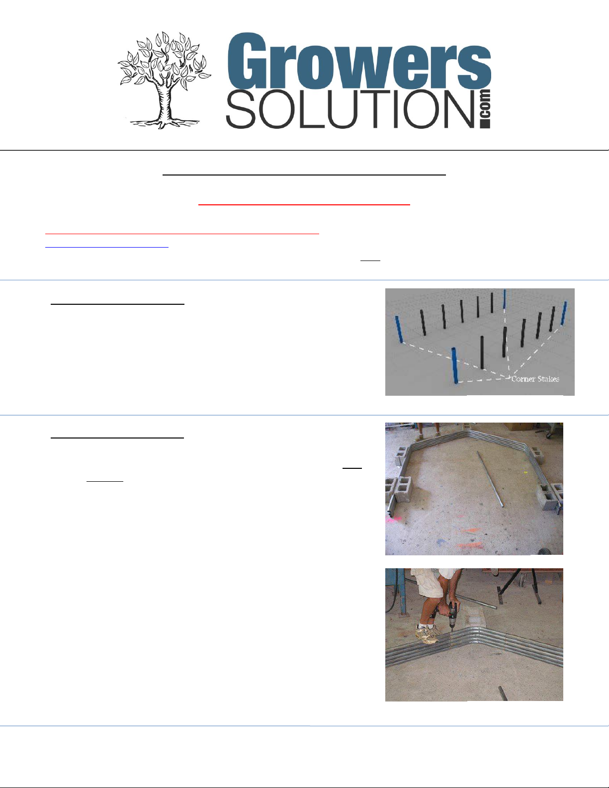
Step 8 –Film Installation
When preparing to install film on your greenhouse be aware of
the wind. Try to pick a calm day. Start by locating the film for
the ends of the greenhouse. Next gather 3 short pieces of
wiggle wire you will use this to hold film in place. Stretch the
film over the bow and attach the film with the wire. You can
adjust film by removing wiggle wire and reinstalling. Once end
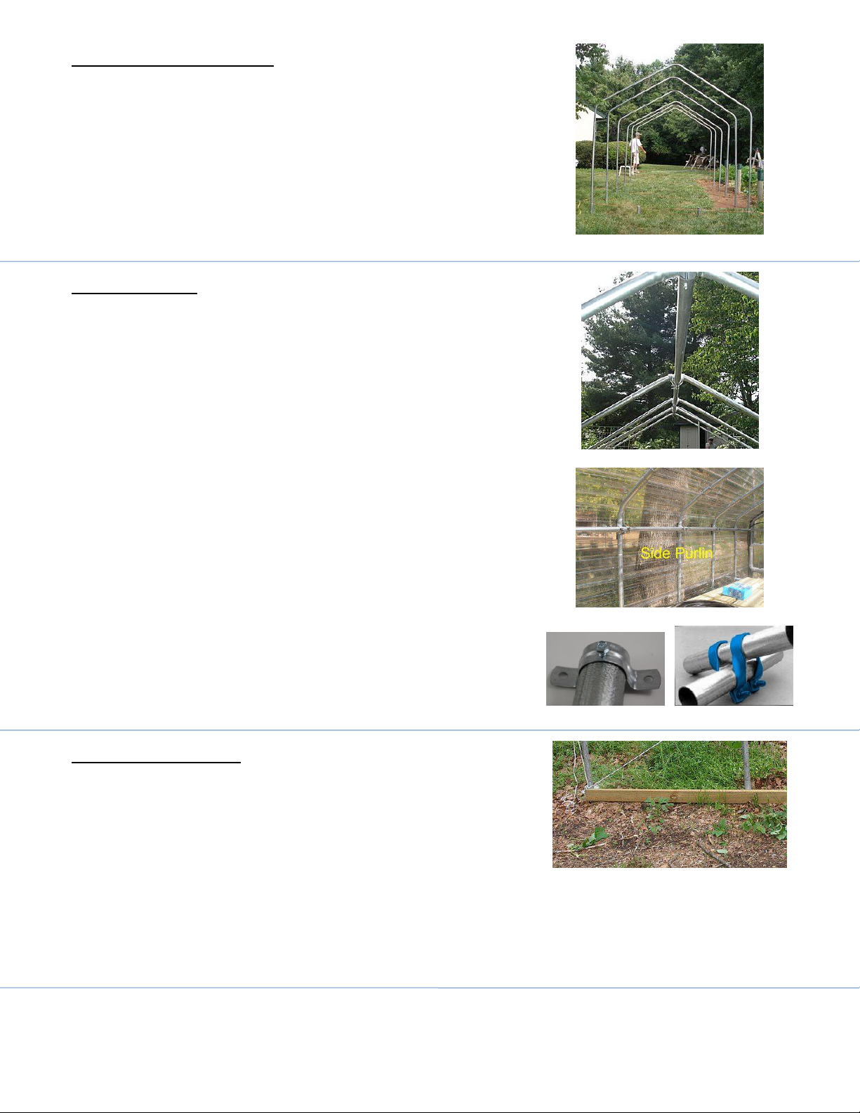
film is in place it is time for the main film. Roll main film out
along side of the green house. Lay wiggle wire out around the
house. Pull film across house and attach on one end. Go to the
other end and pull tight. You may need to go back and adjust
again. Once in place wire lock completely.
Pull Film over the greenhouse (on a non-windy day!)
NOTE: Plastic normally has 12 inches or larger overhang on all sides.
NOTE: Please make sure that you are careful when pulling film. Make
sure film does not get snagged on metal.
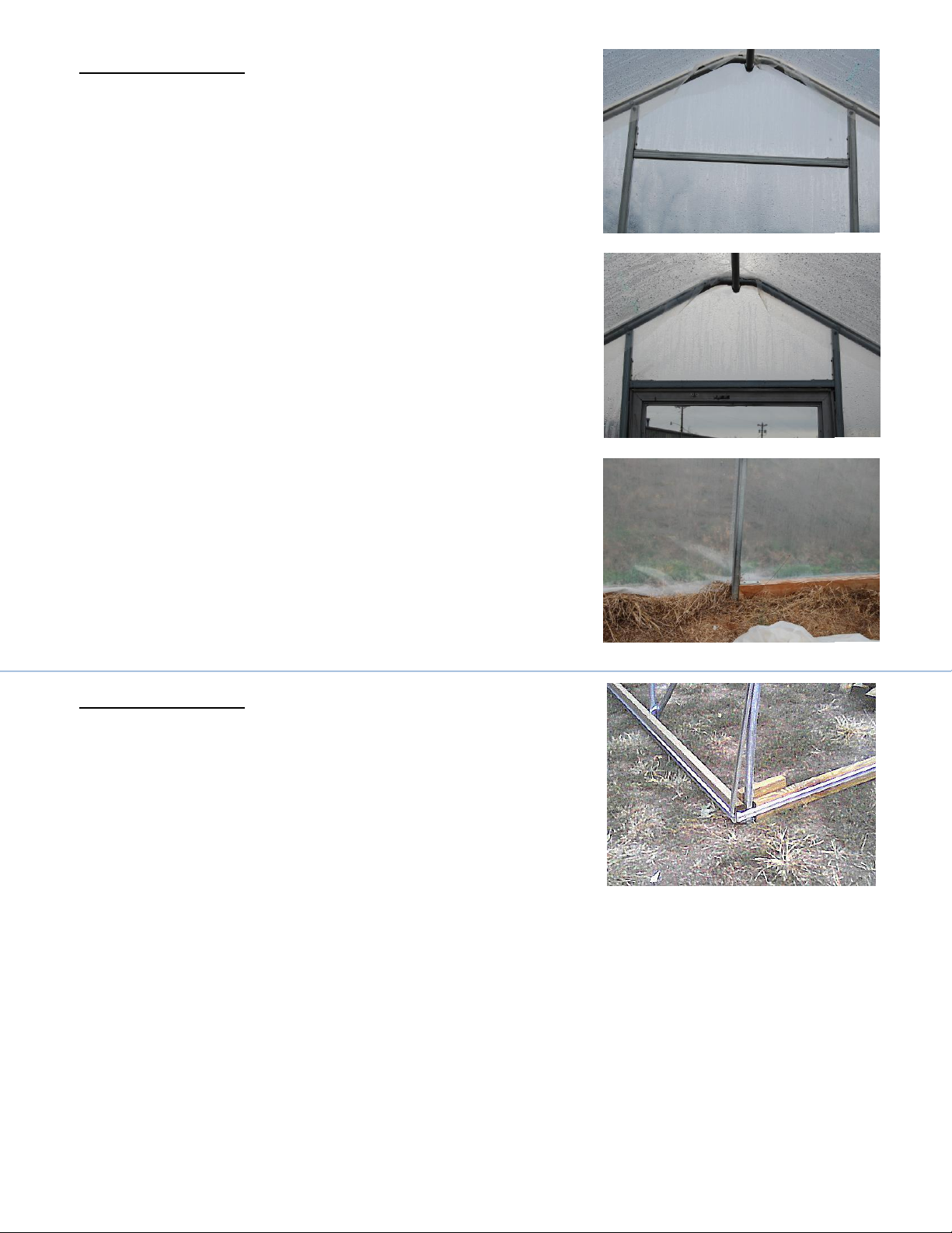
Lay film over the Wire Lock Channel, and fasten the plastic into
the channel by placing the wiggle wire into the channel on top of
the plastic (Fig 8.1).
NOTE: Please watch the video online for more information.
Fig 8.1 Wire Lock / Film Installation
Additional Information Concerning Weather
During windy / stormy / winter conditions it is mandatory to roll sides down and wire lock ends. Lack of
doing this may result in greenhouse damage due to wind uplift. If you are expecting sever snow, 6 inches
plus you should broom snow off of the greenhouse. Feel free to call for more explanation, 931-528-3390.
Please feel free to call us if you have any questions.
GrowersSolution.com 931.528.3390
LIMITATION OF WARRANTY: Grower’s Solution, LLC makes no warranty either expressed or implied, as to any matter in connection with the sale or use of goods or services offered
nor does the company make any warranty of merchantability of fitness for any purpose. Grower’s Solution, LLC Is not responsible for improper assembly or improper installation of
any products. If any item is warranted by the manufacturer, the buyer shall look solely to the manufacturer for redress of the manufacturer’s warranty.
RECOMMENDATIONS: All recommendations by us are compiled for recognized horticultural sources. Because conditions of use which are of critical importance are beyond our
control, we make no warranty or representation, expressed or implied, except that all products conform to the description of the label. We are not responsible for damage or failure
because of any recommendations given by us or our personnel. Our liability as the seller shall be limited to the stated selling price of any defective goods, which in no event shall
include buyers cost, lost profits or good will, or any other special consequential damages.
Other manuals for DAKOTA
1
Table of contents
Other Growers SOLUTION Greenhouse Kit manuals