CLIMA POD Virtue User manual

Walk-in Greenhouse
MODEL A (mm) B (mm) C (mm)
2693
8’10”
2415
7’111/16”
Virtue 4386
14’411/16”
C
B
A
Assembly instructions

2
Climapod Assembly Tips and Tricks
●Prior to the assembly of the greenhouse, you should have a 10mm nut driver,
10mm open-end wrench, Phillips head and slotted screwdriver, spirit level,
ladder, needle nose pliers, flat head screwdriver, and some WD-40 lubricant.
●Caulking Increases the structural integrity of the greenhouse and prevents
water from going into the panels. Caulking the top of the middle seam will pre-
vent algae and water buildup.
●We recommended Henry 212 All Purpose Crystal Clear Sealant
●The base has to be 100% level and square. The easiest way to ensure this is
to make sure that the two diagonal measurements are identical.
●Erection of the greenhouse should only take place in calm and dry weather.
●Pre-Assemble and caulk windows and doors before you erect the greenhouse
●Pre thread aluminum profiles for window and door pieces to make assembly
easier
●Keep bolts loose during assembly and avoid securely attaching (#40) before
the first panel arch has been inserted
●It is far easier to assemble if you have an elevated surface such as two 4’×8’
pieces of plywood on a sawhorses.
Basic Steps to Assembly
1. Prepare Foundation
2. Attach and secure Base and side sills
3. Assemble and Caulk Windows and Doors
4. Assemble Gables
5. Attach Gables to base and side sills and connect with top ridge beam
6. Connect Hanging basket bar, horizontal rails, and partially connect #040
7. On one side begin by inserting B panel, then crossbar, then L1 Panel
8. Secure into place with curved aluminum profile.
9. Continue the process while alternating sides.
10. To fit final panels loosen bolts to partially disconnect front gable and allow for
more space
11. Slide in windows, if needed trim upper corners of arches
12. Install doors and additional accessories
13. Caulk top of outside midseam all around greenhouse

3
Supplementary Instructions
For additional questions or concerns please email sales@climapod.com
or call 360.674.2642
Gather all parts
necessary for as-
sembling the top of
the gable.
Make sure to in-
sert Polycarbonate
pieces into Alumi-
num profiles be-
fore inserting bolts
into channels
Once bolts are in-
serted slightly
tighten nuts, at the
top, working down-
ward to position
and bolt the rest of
the gable.
The completed top of the gable should look like the image on the above.

4
Repeat the steps on the rear gable and continue inserting the rest of the polycarbonate
pieces and aluminum support pieces.

5
Once both gables are completed, insert them into the aluminum base and connect using
the ridgepole

6
Statement
Dear Customer!
May we congratulate you on your new Greenhouse.
We feel sure that by following the detailed assembly instructions you will find as much pleasure in actually
building the greenhouse as the time you will spend in your greenhouse in the future.
The assembly instructions mainly consist of detailed illustrations and no specific technical knowledge is
required for the assembly of the greenhouse.
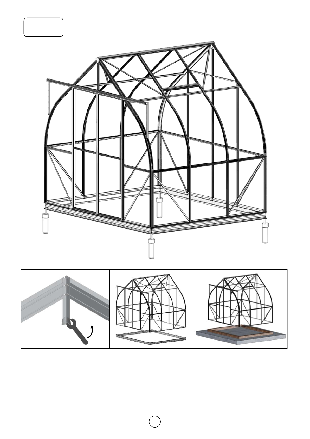
There are four packages for one set of Arched greenhouse totally.
The base is packed in one carton, no matter aluminum base or steel base.
The house frames are packed in two cartons, one for straight profiles and all of fittings, one for curved
frames.
All the polycarbonate panels are packed in one carton.
All of the aluminum profiles are marked with a part number corresponding to the numbers given on the
drawings and in the parts list. Nuts, bolts and fittings will be found in the relevant package.
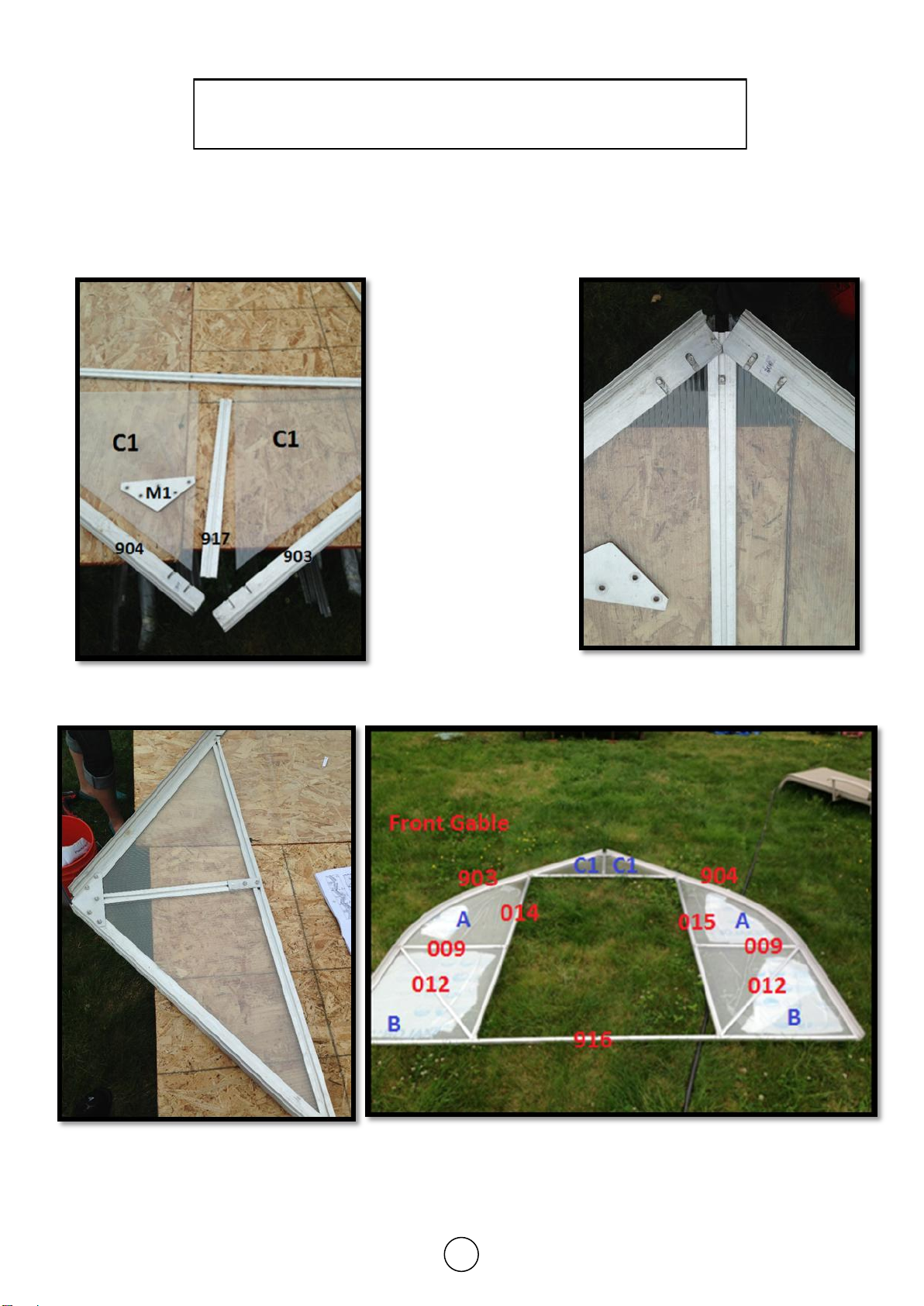
All of the rear gable section straight frames are in package No.1
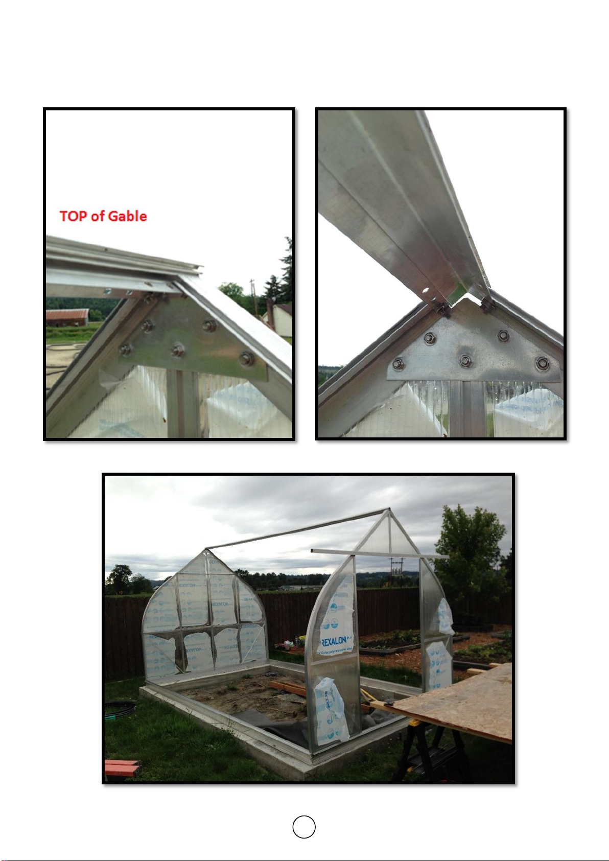
All of the front gable section straight frames are in package No.2
All of the roof/side wall section straight frames are in package No.3
All of the frames and components for the window are in package No.4
All of the frames and components for the door are in package No.5
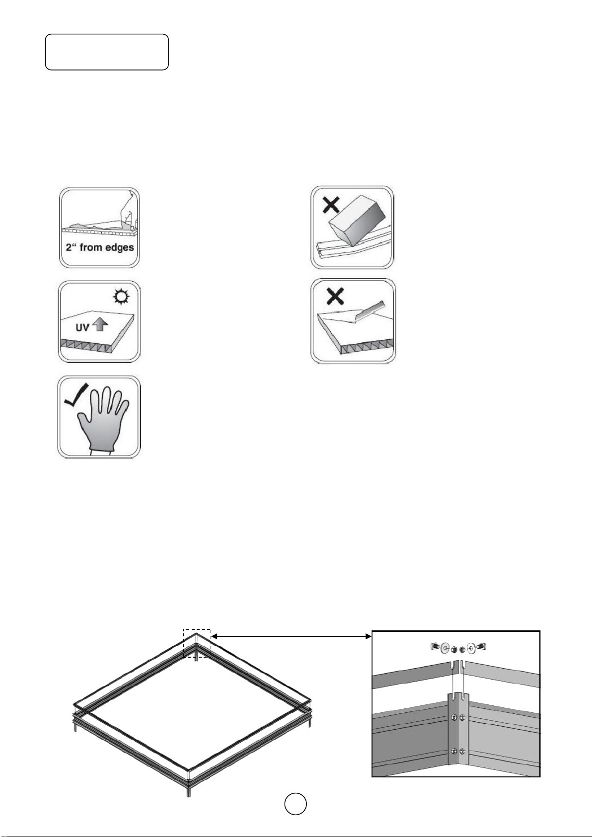
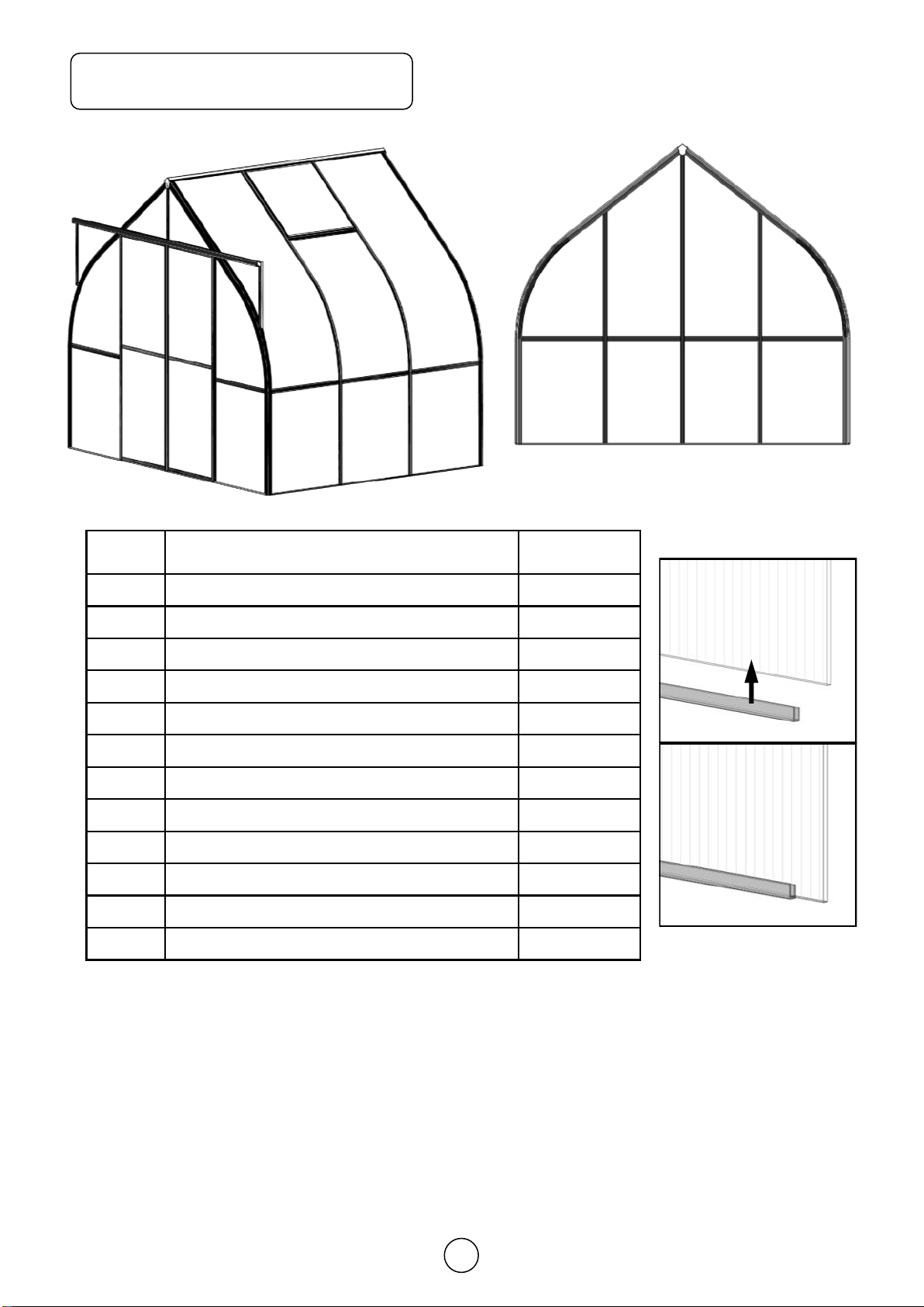
The panels of Polycarbonate are not marked with a part number, but the sizes appear in the overview.
When fitting the Polycarbonate, the side with the opal film/text must turn outward.
Accessories
We offer a wide range of accessories which contribute to a better yield and make life easier for the gar-
dener. A selection of the range is shown in the supplements to these instructions. Your dealer will be
pleased to assist you with further information and a special brochure.
Winter Protection
In areas where snow might be expected we recommend the following in order to protect your green-
house:
1. Support the ridge at the center of the greenhouse.
2. Removed larger snow loads.
3. Take precautions against snow falling down, for instance from a roof.
Complaints
We put severe demands on quality to secure that you get a faultless product. However, should a problem
occur, we kindly ask you to contact the dealer from whom you have bought the greenhouse. For a quick
service, you should specify the extent of the defect by means of the parts list in the assembly
instructions. Please also note the model number which is marked on the front page of these instructions.
Guarantee
We grant a 10 year comprehensive guarantee which covers replacement or repairs of defective parts due
to material or manufacturing defect. The guarantee does not cover polycarbonate, transport, erection.
The guarantee is invalid if the greenhouse is not assembled according to these instructions.
Insurance
Not all insurance companies automatically cover greenhouses. We recommend you contact your insur-
ance company to ensure that you are covered.

7
Statement
Tips
1. The base has to be fastened in a non-freezing depth(80cm).
2. The greenhouse is to be fastened to the base.
3. The base has to be 100% level and square. The easiest way to ensure this is to make sure that the
two diagonal measurements are identical.
4. We recommend that you grease screws for doors and windows for easier assembly.
5. Erection of the greenhouse should only take place in calm and dry weather.
6. All frames are to be assembled around the polycarbonate as shown on the drawings. We recom-
mend that you start with the back gable.
7. IMPORTANT Before assembling aluminum base, the end trough centers of four legs should match
both end trough centers of side sills and front & rear sills at the same time.
Remove approximately 2
inches of film from all
sheet edges before in-
stalling. Remove all film
immediately after the con-
structions is completed.
The UV-protected side of
the sheet is covered with
opal white film/text and
must face towards the
sun.
Please put on gloves
avoid slitting your hands.
Handle with care! Drop-
ping can bend the frame,
and it won’t fit properly.
Keep sharp instruments
away from the polycar-
bonate sheets.
Cautions
Foundation
The base is maintenance free and, of course all fittings are included. Remember to order concrete pipes
and concrete at your local dealer as these are not included in the delivery.
Please match four corner
troughs together at the
same time
side sills
front & rear sills

8
Base
XY
Virtue 2693 4386
XY
Virtue 8’10” 14’411/16”
# m7
Virtue 14
# m5
Virtue 19
# m7
Virtue 19
a2
m7
Alu. Base
a2
m7
Steel
Base
a2
m5
Concrete

9
Base
The left illustration shows length and width marked with “X” and “Y”. Part No. m5 shows
a bracket used to secure the inside base when not using the original supplier’s founda-
tion.
Prior to the assembly of the greenhouse, you should have a 10 mm nut driver, 10 mm
open-end wrench, Philips head and slotted screw driver, spirit level, and some WD-40
lubricant.
When using the aluminum base remember to fill the channels with bolts corre-
sponding to amount of arches per side as well as connecting gables.

10
Polycarbonate sheet
# Size Virtue
A700x1049 (2’39/16” x 3’55/16”) 4
B700x842 (2’39/16” x 2’91/8”) 16
C1 602x487/16 (1’1111/16” x 1’73/16” / 5/8”) 2
D599x913 (1’119/16” x 2’1115/16”) 4
E1 610x1534/1057 (2’ x 5’3/8” / 3’55/8”) 2
F610x842 (2’ x 2’91/8”) 2
G1 700x1330 (2’39/16” x 4’43/8”) 4
H1 696x731 (2’33/8” x 2’43/4”) 4
I1 700x2110 (2’39/16” x 6’111/16”) 8
p6 592 (1’115/16”) 2
p7 682 (2’27/8”) 12
p8 660 (2’2”) 4
I1 G1 AA
A
A
D
D
B
B
BB
E1
F
H1
C1
p6p8 p8
p8
p8
p7
This page shows the positioning of the polycarbonate panels for the front and rear gable as
well as the roof and the sides. It also indicates where the parts #P6, #P7 and #P8 are used.
When fitting parts #P6/P7/P8 on the ends of the panels, try using a narrow piece of bar soap
through the part first. It will allow it to slide on much easier. #P6/P7/P8 must be fitted on one
end of polycarbonate in advance before polycarbonate be inserted into aluminum frame.
The square illustration on the page shows the placement of the gray plastic U shape strips. To
transfer the size of the panels from mm to inches, divide by 25.4.
p6/p7/p8
p6/p7/p8
BBB
E1
F
p6
C1
D
D
I1
p7 p7

11
Louvre
PC Panel 573x97x4mm
Alu. profile
Alu. profile
L573 x 97 5
p6
p6
the new polycar-
bonate panel #E1
Using Alu. clip
to connect louvre and PC panel
p6
Louvre is an optional extra and is not
included in the price.
475
(1’611/16”)
456
(1’515/16”)
456 x 610
(1’515/16” x 2’)

12
Section Part
No. Profile Size Virtue
V
E
N
T
V042 683 (2’27/8”) 4
V044 698 (2’31/2”) 4
V045 698 (2’31/2”) 4
V946 750 (2’51/2”) 8
047 300 (1113/16”) 4
048 200 (77/8”) 4
D
O
O
R
V049 586 (1’111/16”) 2
V050 586 (1’111/16”) 4
V051 1864 (6’13/8”) 2
V952 1864 (6’13/8”) 1
V953 1864 (6’13/8”) 1
054 558 (1’915/16”) 2
a1 M6x10 154
a2 M6 173
a3 M6x18 3
a4 Φ4.2x9.5 16
a5 Φ3.5x19 20
a6 Φ3.5x35 12
a7 Φ4x8 4
a8 M6x15 12
a9 M6x15
crop 4
a10 Φ3x10 4
a11 M3 4
m1 -2
m3 -9
m6 -2
n1 -4
p1 -2
p3 -8
p4 -4
p5 -2
p6 592 (1’115/16”) 2
p7 682 (2’27/8”) 12
p8 660 (2’2”) 4
m11 -1
FLUFF 3.8m 1
The list of Section
Section Part
No. Profile Size Virtue
R
E
A
R
V901 2960 (9’89/16”) 1
V902 2960 (9’89/16”) 1
V005 1912 (6’31/4”) 1
V006 1912 (6’31/4”) 1
V907 2377 (7’99/16”) 1
908 1268 (4’115/16”) 1
V009 683 (2’27/8”) 2
V010 594 (1’113/8”) 2
911 2662 (8’813/16”) 1
057 1100 (3’75/16”) 2
V913 2662 (8’813/16”) 1
F
R
O
N
T
V903 2960 (9’89/16”) 1
V904 2960 (9’89/16”) 1
V009 683 (2’27/8”) 2
057 1100 (3’75/16”) 2
V014 1912 (6’31/4”) 1
V015 1912 (6’31/4”) 1
V916 2662 (8’813/16”) 1
V917 460 (1’61/8”) 1
V918 1220 (4’1/16”) 1
V919 2484 (8’113/16”) 1
056 707 (2’313/16”) 2
R
O
O
F
/
S
I
D
E
V024 4345 (14’31/16”) 1
V029 4324 (14’21/4”) 2
034 4311 (14’13/4”) 2
039 4311 (14’13/4”) 2
012 1100 (3’75/16”) 8
V042
683 (2’27/8”) 12
V943
2954 (9’85/16”) 10
955 400 (1’33/4”) 5

13
1
V005 V006 V907 908 V009 911 057 V913 m1 a1 a2V901 V902Part p6 p8V010 p1a9
1912
6’31/4”
1912
6’31/4”
2377
7’99/16”
1268
4’115/16”
683
2’27/8”
2662
8’813/16”
1100
3’75/16”
2662
8’813/16”-M6x10 M6
2960
9’89/16”
2960
9’89/16”
Size 592
1’115/16”
660
2’2”
594
1’113/8”-
M6x15
11112121124 2611Qty 22212
908
AA
E1
BB
F
2
34
5
Rear Gable
Step1
With this page, you will assemble the rear gable (back). It is far easier if you have an elevated surface
such as two 4’×8’ pieces of plywood on a sawhorses. If not, lay the aluminum profiles out on a hard sur-
face as shown in the main illustration. Remember you are building from the inside with the outside facing
down. Start with one of the “E1” panels and build the aluminum around the polycarbonate panel. the
polycarbonate side with the opal film/text must facing down.
Package No.1
V005 V006
V901 V902
V009 V010 V009
911
057057
V913
6
E1
V907
F
V010

14
2
1Square No.1 This
the Ridge. The
square headed bolt
slides into the chan-
nel in part #V901 &
#V902, and connect
them with part #m1,
Our bolts and nuts
were made of
stainless steel.
Square No.2 Insert part #V005 into
Part #V901 channel, contact with part
#908 together, Please insert extra bolt
#a1 into the channel of Part #V006 for
attaching part #911 use later. Do the
same for the opposite end.
Note: Please connect Part #911 with Part #V901, #V902, #V005, #V006,#V907
firstly before you are inserting PC panel #A &#E1 into profiles’ channel.
3A
Square No.3 After PC
panels in position, then
dismantle part #911 and
adjust the distance same
between PC panel and
keyway edge.
V902V901
m1
908
V005
V901
V901
911
V009
057
911
V901
A
V009
V901 V902
908
911
V006V005
AA
V009 V009V010
AA
E1
V907
V907
E1
E1
E1
V010
Section View
V009
a9 a9 is a
cropped
head
bolt
a9

15
4
BBF
5
6Square No. 5
Inserting PC panel
#B,#F in profiles’
channel. With PVC
anti-dust strip #p6
& #p8 on bottom.
Square No.6
Connect Part
#V913.
Please note: 4 Bolts will need to be slid into each Part #V901 and #V902 for ridge, hanging basket bar or horizontal rail
and side sill beam in advance, Finger tightens the nuts for later use.(Bolts and nuts in Package No.3 of Roof/Side wall)
When finished with the back gable, stand it up out of the wind so it will not blow over.
Square No. 4 Assembly part #V009, #V010 in place, then connect with part #911 again.
911 V010
911
V009
p8
V913
p8 p6 p8
V913
p6
V913
p8
057
p6
F
Please Note: Don’t let this bolt block polycarbonate panel to
insert into part #V901&V902 alu. frame channel. Insert PC panel
first, then slide this bolt in part #V901&V902 profile’s trough.
V901 V902 V901

16
Front Gable
Step2 Package No.2
Square No.1
this step is
very much like
the rear gable.
V009 057 V014 V015 V916 V917 V918 V919 m1 m3 a1V903 V904Part a2 a3 p8p1a9056
683
2’27/8”
1100
3’75/16”
1912
6’31/4”
1912
6’31/4”
2662
8’813/16”
460
1’61/8”
1220
4’1/16”
2484
8’113/16”--
M6x10
2960
9’89/16”
2960
9’89/16”
Size M6
M6x18
660
2’2”
-
M6x15
707
2’313/16”
22111111111811Qty 23 32122
AA
BB
V009 V009
V903 V904
057 057
V916
V014 V015
V918
V919
C1
1
4
6
7
5
3
1
V901V902
m1
V917
C1
V917
2
056056

17
Square No.3
Assemble
polycarbonate
panel #C1 on
part
#V903,#V917,
#V904, use
part #V918 to
fix it.
C1
V918
3
V918
V904
V015
AA
V009 V009
4V904
V009
Square No.4 Af-
ter PC panels in
position, then adjust
the distance same
between PC panel
and keyway edge.
a3
C1
2
V918
V917
a3
m3
V903 V904
V903 V904
a9
Section View
V009
a9 is a
cropped
head
bolt
a9
5V014 V009
056
056
057
a9
V904
Square No.5 Use
the part #056 to con-
nect the part #V009
& #V014.

18
Please note: 4 Bolts will need to be slid into each Part #V903 and #V904 for Ridge, hanging basket bar or horizontal rail
and Side sill beam in advance, Finger tightens the nuts for later use.(Bolts and nuts in Package No.3 of Roof/Side wall)
Square No.8 The bolt #a3 to fix #V918 is an extra
long stainless bolt. The bolt slides into part #V919 and
extends through parts #V903 & #V904.
V919
a3 V919
a3
B
p8
B
p8
V916
6V904
V916
p8
7
8
p8
V916
057
V014
Section view
V918
Square No. 6
Inserting PC panel
#B in profiles’
channel. With PVC
anti-dust strip #p8
on bottom.
Square No.7
Connect Part
#V916.
Please Note: Don’t let this bolt block polycarbonate panel to in-
sert into part #V903&V904 alu. frame channel. Insert PC panel
first, then slide this bolt in part #V903&V904 profile’s trough.
V903 V904

19
Part No. Size Virtue
V024 4345
14’31/16”1
V029 4324
14’21/4”2
1
2
2
1
Step3 Connect front gable with rear gable by Ridge and side sill beam.
Square No.1 Attaching the ridgepole to the gables, this is
where you may have to adjust bolts in plate #m1 to fit the
pole into gables. Slide the bolt with the nut on up the trough
of ridgepole and tighten.
Square No.2 Connect side sill beam with
curved corner bar, this can be one of the easi-
est. This is where you will use an open-end
10mm wrench. Because of the tight corner, it is
difficult to work with the nut driver. Once you
have attached side sill to curved corner bar,
bring the corner together and slide the bolt down
into the slot. Tighten with the open-end wrench.
m1
a1/a2

20
2
2
1
Assemble greenhouse frame on Alu. base.
m7
Square No.1 You may
loosen the bolts in cor-
ners and re-tighten it at
the trough of base legs.
Square No.2 Assemble
greenhouse frame on
base by connector m7 in
the middle of bottom.
a8-M6x15
Center
1
Corner
a1-M6x10 a1-M6x10
Corner
Center
a8-M6x15
This manual suits for next models
3
Table of contents
Other CLIMA POD Greenhouse Kit manuals