Overload protection: 250V DC/250Vrms AC
2.2.8 AC/DC Watt and Cosαtest
Range Accuracy Resolution
40kW 3.5% of rdg+5 digits 0.01kW
400kW 3.5% of rdg+5 digits 0.1kW
Cosα
(0.2~1.0)
±0.2,Voltage≥250V,Current≤50A 0.01
±0.1, Current>50A
NOTE:
1. Minmum measurement voltage: DCV45V/ACV45V,
Maximum measurement voltage: DCV600V/ACV600V.
2. Minmum measurement current: DCA 10A/ACA 10A,
Maximum measurement current: DCA1000A/ACA1000A.
3 .If meter display negative,reversed the clamp or test lead.
2.2.9 Temperature(NiCr-NiSi sensor)
Range Accuracy Resolution
℃-20~300℃3.0% of rdg+3 digits 1℃
300~1000℃3.5% of rdg+3 digits
Overload protection: 36V DC/36Vrms AC
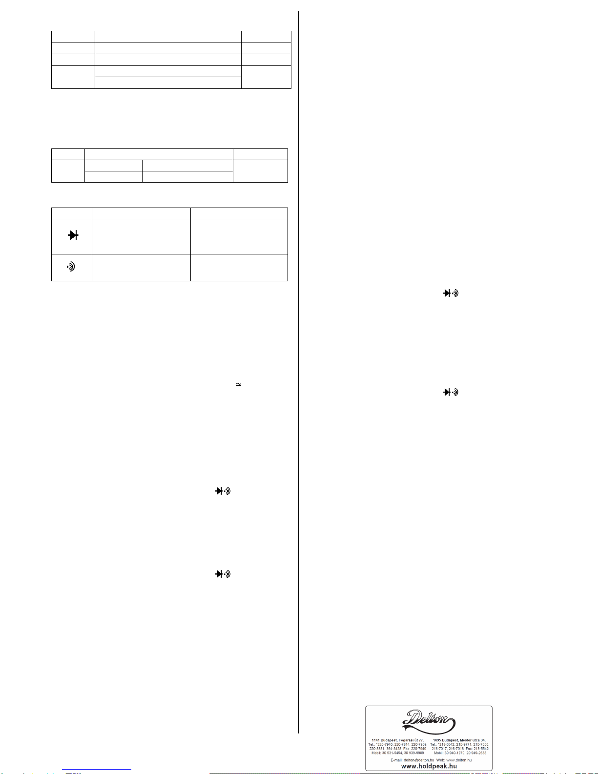
2.2.10 Diode and Audible continuity test
Overload protection: 250V DC/250Vrms AC
3. MEASURING INSTRUCTION
3.1 DC/AC Voltage or Frequency Measurement
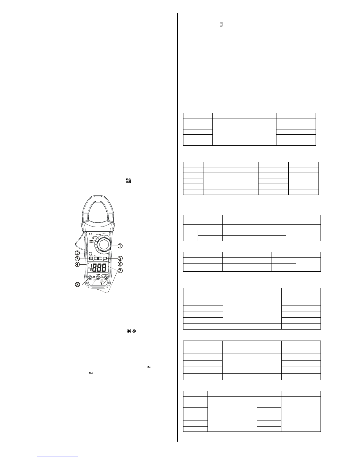
1) Connect the black test lead to "T-COM" socket and red test
lead to the " T+VΩHz " socket.
2) Set the “SELECT”key to desired DC /AC test or Set the
“Hz/Duty”key to desired Hz/Duty test
3) connect the probes across the source or load under
measurement.
4) Read the result from the LCD panel.
Note: Non vnit sign display of DC at DC voltage/current test.
3.2 DC/AC Current Measurement
1) Set the Rotary switch to desired “
”position.
2) Set the SELECT key to desired DC or AC test
3) Press the "RANGE" Key to select 400A or 1000A range, Press
the "REL" Key, the display show "0", ACA auto Zero.
4) Open the clamp by pressing the jaw-opening handle and insert
the cable to be measured into the jaw.
5) Close the clamp and get the reading from the LCD panel.
Note:
Before this measurement, disconnect the test lead with the
meter for safety.
3.3 Resistance Measurement
1) Connect the black test lead to " T-COM " socket and red test
lead to the " T+VΩHz " socket.
2) Set the Rotary switch to desired "ΩCAP " position, the
present function is resistance measurement, if it is other
function,pushtheSELECTKeyto selectresistancemeasurement..
3) Connect the probes across circuit to be tested.
4) Read the result from the LCD panel.
Caution: Ensure that the circuit to be tested is "dead".
Max.input over-load: 250V rms<10sec
3.4 Capacitance Measurement
1) Connect the black test lead to "T-COM" socket and red test
lead to the "T+VΩHz" socket.
2) Set the Rotary switch to desired "ΩCAP " position.
3) push the SELECT to select capacitance measurement.
4) Connect the probes to the capacitance to be tested.
5) Read the result from the LCD panel.
Caution:
a) Capacitors should be discharged before being tested.
b) When testing large capacitance, it will take longer time before
the final indication(For 100uF range, it will take about 15
seconds).
c) When testing small capacitance, to assur the measurement
accuracy, first press "REL", then go on measureing.
Max.input over-load: 250V rms<10sec
3.5 WATT measurement
1) Connect the black test lead to "T-COM" socket and red test
lead to the " U" socket.
2) Set the Rotary switch to desired "40kW "or"400kW" position.
3) Connect the red test head to the live wire of the load by test
and connect the black test head to the N-wire of the load by
test, Push the " REL " Key Until the meter display “000”.
4) Open the clamp by pressing the jaw-opening handle and
clamp the live wire of the load by test, Let the live wire through
The clamp from surface of the meter,The meter will display
working power of the load by test。
Notice:
If meter display negative,reversed the clamp or test lead.
3.6 Cosα TEST
1) Set the Rotary switch to desired " Cosα" position.
2) The way of Connection wire,Please reference 3.5 item 1) ,3),4)
3) The meter will display power factor of the load by test。
Notice:The meter will display “OL”when test value is negative
Cosα ,then reversed the clamp or test lead.
3.7 Temperature Measurement
1) Connect the black test lead of the sensor to "T-COM"
socket and the red test lead to the " T+VΩHz " socket.
2) Set the Rotary switch to "Temp" position.
3) Put the sensor probe into the temperasure field under
measurement.
4) Read the result from the LCD panel.
Max.input over-load: 250V rms<10sec
A. The temperature function shows the random number at
ordinary times, must insert the thermocouple in temperature test
hole while examining temperature.
B. This meter inclosure WRNM-010 type contact thermocouple
limit temperature is 250 ℃(300 ℃shortly ) ;
C. Please don't change the thermocouple at will , otherwise we
can't guarantee to measure accuracy ;
Please don’t importing the voltage in the temperature function.
D. Please use special probe for test high temperature.
3.9 Diode Test
1) Connect the black test lead to "T-COM" socket and red test
lead to the " T+VΩHz " socket.
2) Set the Rotary switch to "ΩCAP " position.
3) Push "SELECT" to select diode test.
4) Connect the black and red test probe to the cathode (-)
and anode (+) ends of diode to be tested
repectively, read the forward voltage drop (junction) value
from the display. If reverse connected the probes to diode,
display shows over-load.
Caution: Ensure that the circuit to be tested is "dead".
Max.input over-load: 250V rms<10sec
3.10 Audible Continuty Test
1) Connect the black test lead to "T-COM" socket and red test
lead to the " T+VΩHz " socket.
2) Set the Rotary switch to "ΩCAP " position.
3) Push "SELECT" to select Audible continuty test.
4) Connect the probes across circuit to be tested, the beeper
sounds continuously if the resistance is less than approx. 60Ω.
Caution: Ensure that the circuit to be tested is "dead".
Max.input over-load: 250V rms<10sec
4. CARE AND MAINTENANCE
4.1 CARING FOR YOUR MULTIMETER
Your Digital Multimeter is an example of superior design and
craftsmanship. The following suggestions will help you care for
the multimeter so you can enjoy it for years.
1) Keep the multimeter dry. If it gets wet, wipe it dry immediately.
Liquids can contain minerals that can corrode electronic circuits.
2) Use and store the multimeter only in normal temperature
environments. Temperature extremes can shorten the life of
electronic devices, damage batteries and distort or melt plastic parts.
3) Handle the multimeter gently and carefully. Dropping it can
damage the circuit boards and cause and can accuse the
multimeter to work improperly.
4) When take current measurement, keep the cable at the center
of the clamp will get more accurate test result.
5) Keep the multimeter away from dust and dirt, which can cause
premature wear of parts.
6) Wipe the mutimeter with a damp cloth occasionally to keep it
looking new. Do not use harsh chemicals, cleaning solvents, or
strong detergents to clean the multimeter.
7) Use only fresh batteries of the required size and type. Always
remove old or weak batteries. They can leak chemicals that
destroy electronic circuits.
8) Please take out the battery when not using for a long time.
4.2 9Volt battery replacement
1) Ensure the instrument is not connected to any
extemal circuit. Set the selector switch to "OFF" position and
remove the test leads from the terminals.
2) Open the cover of the battery cabinet by a screwdriver.
3) Replace the old batteries with the same type batteries.
4) Close the battery cabinet cover and fasten the screw.
Range Description Test condition
“Display read approx.
Forward voltage of
diode.
Forward DC current
approx. 0.4mA
Reversed DC voltage
approx. 1.5V
”Built-in buzzer sounds
if resistance is less
than 60Ωapprox. Open circuit voltage
approx. 0.5V