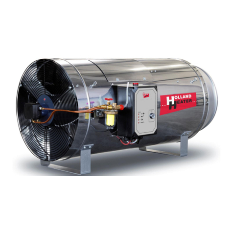
HOLLAND HEATER HHB-40 User manual

HOLLAND HEATER USER MANUAL
HHB Air heater May 2013
Air heater type HHB-40

HOLLAND HEATER USER MANUAL
General
April 2012 HHB Air heater
2
HOLLAND HEATER
Air heater
HHB-40
Many thanks for your confidence in us!
We are convinced that you will be satisfied!
0461BT0933
EC – declaration of conformity
Certificate of Origin
We hereby declare that the models and versions of the above-mentioned appliance, as
launched onto the market by ourselves, comply with the European health and safety
guidelines.
N.B.
We kindly request that you carefully read the operating instructions, prior to using your new
appliance for the first time, in order to guarantee that your new system operates correctly and
efficiently and in order to increase your personal safety. You should especially take note of
the warning symbols.

HOLLAND HEATER USER MANUAL
General
HHB Air heater April 2012
3
1 Holland Heater
All rights reserved. No part of this publication may be reproduced and/or published by means
of print, photocopy, microfilm or any other means, without the prior written permission of
Holland Heater. This similarly applies to the accompanying drawings and diagrams.
Holland Heater reserves the right to change parts at any time, without informing the
consumer either directly or prior to doing so. The content of this manual is also subject to
change, without prior notification.
This manual applies to the standard design air heater. Holland Heater therefore cannot be
held liable for any damages arising from changes made to the specifications of the standard
design appliance.
Please contact your supplier for information not included within this manual relating to
adjustments, maintenance work or repairs.
This manual has been compiled with the utmost care and attention; however Holland Heater
cannot accept responsibility for any errors within this book or the consequences of such
errors.
PLEASE TAKE THE TIME TO READ THIS DOCUMENT CAREFULLY BEFORE USING
YOUR AIR HEATER.
THIS DOCUMENT SHOULD ALWAYS BE KEPT WITHIN REACH OF THE AIR HEATER.

HOLLAND HEATER USER MANUAL
General
April 2012 HHB Air heater
4
GENERAL MANUAL
1
Holland Heater........................................................................................................3
2
General....................................................................................................................5
2.1
Foreword..................................................................................................................5
2.2
Pictograms and symbols...........................................................................................6
2.3
Service and technical support...................................................................................6
2.4
Warranty provisions..................................................................................................6
2.5
Identification of the air heater....................................................................................7
2.6
Ordering parts...........................................................................................................7
3
Safety regulations and hazard warnings...............................................................8
3.1
General.....................................................................................................................8
3.2
User manual.............................................................................................................8
3.3
Pictograms and instructions on the air heater...........................................................8
3.4
Users........................................................................................................................8
3.5
Intended use.............................................................................................................9
MANUAL FOR AUTHORISED PERSONS
4
Technical specifications ......................................................................................10
4.1
Safety devices........................................................................................................11
4.2
Modifications...........................................................................................................11
4.3
Installation..............................................................................................................11
4.4
Use.........................................................................................................................11
5
Installation.............................................................................................................12
5.1
Gas connection.......................................................................................................12
5.2
Electrical connection...............................................................................................12
5.3
General points........................................................................................................14
6
Operation ..............................................................................................................15
6.1
General functioning.................................................................................................15
6.2
Operation................................................................................................................16
6.3
Introduction.............................................................................................................19
7
Maintenance..........................................................................................................21
8
Conversion to another gas type ..........................................................................22
9
Troubleshooting ...................................................................................................24
9.1
General...................................................................................................................24
9.2
Burner relay response to malfunctions....................................................................24
9.3
Burner relay status indicator...................................................................................25
9.4
Burner relay malfunction indicator...........................................................................26
9.5
Malfunctions and potential solutions.......................................................................27
9.6
Technical support...................................................................................................29
10
Annexes ................................................................................................................30

HOLLAND HEATER USER MANUAL
General
HHB Air heater April 2012
5
2 General
2.1 Foreword
Use of this document:
This document is intended as a reference work, which may be used only by authorised
persons for the purpose of safely installing, using and maintaining the product indicated on
the cover of this document.
Holland Heater B.V. shall not be held liable for any damages or injuries arising as a result of
failure to comply with the instructions provided within this manual.
The air heater has been designed and manufactured with the utmost care and attention to
ensure that it will provide you with many years of service.
The air heater complies with the NEN-EN 12669 European standard and bears the CE
quality mark.
As a consequence of this, modifications to the air heater are not permitted.
Prior to being supplied to you, this air heater has been subjected to a close inspection. To
ensure that your air heater continues to serve you for many years, without any problems, we
advise you to contact an authorised specialist to service your appliance once every year. If
you follow the instructions in this manual, you can rest assured that you will enjoy your air
heater for many years to come.

HOLLAND HEATER USER MANUAL
General
April 2012 HHB Air heater
6
2.2 Pictograms and symbols
You may encounter the following pictograms and symbols on the air heater and in this
document.
TIP
Suggestions and recommendations intended to enable you to perform the
relevant procedures more easily.
WARNING
Procedures which – when not performed with the necessary caution – can cause
damage to the air heater or the environment or bodily injury.
WARNING
Risk of electrocution.
WARNING
Risk of burns.
WARNING
Take care when using high pressure hose.
RECYCLING
2.3 Service and technical support
For information regarding specific adjustments, maintenance or repair work that fall outside
the scope of this document, please contact your supplier. Your supplier is always ready to
assist you. Please ensure that you have the information on the identification plate to hand.
2.4 Warranty provisions
The sales and warranty provisions applicable to the air heater, as per the Metaalunie
conditions, form part of the terms and conditions of delivery.
Holland Heater is registered with the Haaglanden Chamber of Commerce under number
27226471.

HOLLAND HEATER USER MANUAL
General
HHB Air heater April 2012
7
2.5 Identification of the air heater
The identification plate of your air heater is fixed to the appliance. This lists the correct
information for the air heater supplied. The figure below shows an example of a possible
identification plate.
2.6 Ordering parts
It is essential that you state the following information when ordering parts:
•The item number for the part you wish to order.
•The name of the part you wish to order.
•The model and serial number of the air heater for which the part is intended.
•The voltage to which your air heater is connected.
Holland Heater
Oud Camp 5,
3155 DL Maasland
The Netherlands
0461BT0933
Manufacturer:
Holland Heater
HHB-40
A3
2013
230 Volt-50 Hz
0.9 Amp
230 Watt
131----
40 kW
10.2 mbar
25 mbar
50 mbar
G20 I
2L
Model:
Type:
Year:
Voltage:
Power:
Capacity:
Serial number:
Nominal load:
Burner pressure:
Min. connection pressure:
Max. connection pressure:
Gas category:
Destination country:

HOLLAND HEATER USER MANUAL
General
April 2012 HHB Air heater
8
3 Safety regulations and hazard warnings
3.1 General
•The manufacturer accepts no liability for damage or injury arising as a result of failure to
comply (strictly) with the safety regulations and instructions in this document, or as a
result of carelessness during installation, use or maintenance of the appliance indicated
on the cover of this document or any accompanying accessories.
•Depending on the specific working conditions or accessories used, additional safety
instructions may need to be taken into consideration. Please contact your supplier
immediately in the event that you observe a potential hazard when using the air heater.
•The user of the air heater is at all times fully responsible for following the site safety
regulations and guidelines.
3.2 User manual
•Any person working on or with the air heater must be aware of the content of this user
manual and must follow the instructions herein precisely. The management must use this
manual to train personnel and must observe all instructions and directions.
•Never change the order of the actions to be performed.
•Always retain this document in a fixed location, in close proximity to the air heater.
3.3 Pictograms and instructions on the air heater (if present)
•Pictograms, warnings and instructions shown on the air heater form part of the safety
precautions in question. Under no circumstances must they be covered or removed and
they must remain in place and legible throughout the entire service life of the air heater.
Pictograms, warnings and instructions that have become illegible must be replaced or
repaired immediately.
3.4 Users
•The operation of the air heater is reserved for persons who have been trained using this
document.

HOLLAND HEATER USER MANUAL
General
HHB Air heater April 2012
9
3.5 Intended use*
•The air heater has been designed for the purpose of heating poultry and livestock
houses. Without ventilation, the dimensions of the room should total at least 200m
3
per
m
3
/h gas consumption.
•For the purpose of heating rooms occupied by persons. The approval of the Directorate-
General for Labour in Voorburg is required for this application. The room must be well
ventilated at all times.
•Any other, additional usage is not considered to be in accordance with the intended
purpose. The manufacturer accepts no liability for damages or injury arising from such
use. The air heater is in keeping with the applicable standards and guidelines. Use the air
heater only when in perfect technical condition and only in accordance with the intended
purpose, as described above.
The "Intended use", as laid down in EN 292-1, is the use for which the technical product
is suited, as specified by the manufacturer and inclusive of the instructions in the sales
brochure. If in doubt, the “intended use” is what appears to be the ordinary use when the
construction, design and function of the product are taken into consideration. Using the
product as intended also comprises following the instructions in the directions for use.

HOLLAND HEATER USER MANUAL
For authorised persons
April 2012 HHB Air heater
10
4 Technical specifications HHB-40
Description: Unit: Value: Unit: Value:
Nominal load at upper limit kW 40 Btu 136.136
Gas consumption natural gas (L-gas, 15°C) m
3
/hour
4.3
Gas consumption propane kg/hour 2.9
Natural gas injector mm 8 x ø 2,1 Inch 10 x ø 0,083
Propane injector mm 8 x ø 1,4 Inch 8 x ø 0,055
Burner pressure natural gas - G20* mbar 10,2 Pa 1020
Burner pressure natural gas - G25 mbar 15 Pa 1.650
Burner pressure propane - G31 (30 mbar) mbar 22 Pa 2.200
Burner pressure butane - G31 (50 mbar) mbar 18,4 Pa 1.840
Connection pressure natural gas mbar 25 Pa 2.500
Connection pressure propane mbar 50 Pa 5.000
Connection voltage 1 phase (phase-sensitive)
VAC 230
Remote control VDC 24
Power consumption Watt 265
Current consumption Amp 1.3
Air displacement m
3
/hour
3800
Throw M +/- 35 ft +/- 114
Revolutions per minute - fan rpm 1.500
Repeat start-up 3x Sec 4
Ionisation current (normal) µA 10 - 15
Mass of appliance Kg 32 lbs 70,6
Length (A) mm 1036 Inch 40.82
Width (B) mm 582 Inch 22.94
Height (C) mm 509 Inch 20.06
See annexe A for differing types of gas.

HOLLAND HEATER USER MANUAL
For authorised persons
HHB Air heater April 2012
11
4.1 Safety devices
•All safety devices must be fitted correctly and may only be removed by trained and
authorised service technicians for the purpose of maintenance and repair works.
•The air heater must never be used when the safety devices are not complete or are not
fitted or if the devices have been turned off or rendered inoperative.
•The safety devices must be checked regularly to ensure they are operating correctly and,
if necessary, be repaired immediately by service technicians.
4.2 Modifications
•It is prohibited to modify the air heater in any way.
•The specifications outlined in this document must not be changed.
4.3 Installation
•The installation, maintenance and repair of the air heater and any adjustments must only
be carried out by authorised service personnel.
•Allow enough free space to the left and right of the air heater to enable maintenance and
repair works to be carried out.
•The air heater must be connected to a reliably earthed and watertight wall socket at all
times. With regard to service and maintenance work, the plug may only be removed from
the wall socket once the air heater has completed the cooling procedure. This will take at
least 1.5 minutes.
•Bear in mind that the air heater is phase-sensitive. See section 5.2.
•The air heater must never be connected to a duct system.
4.4 Use
•Inspect the air heater prior to use and check for damages.
•Avoid exposing the air heater to water and moisture for long periods of time.
•Keep the control instruments free from dirt and grease.
•Never use sharp objects in order to operate the appliance.
•Bear in mind that some parts of the air heater become hot during use.
•When the air heater is not used for long periods of time, remove the plug from the wall
socked and shut off the gas supply.
The plug must not be removed from the wall socket at any time whilst the air
heater is in use. The same applies to removing the supply in any way
whatsoever. You are only permitted to do so once the air heater has completed
the cooling procedure, which takes at least 1.5 minutes. If this instruction is not
followed, the temperature safety mechanism will be activated.
Note!
The air heater is phase-sensitive. In order for the air heater to function, it
is essential that the plug is inserted into the wall socket in the correct manner.
See section 5.2.

HOLLAND HEATER USER MANUAL
For authorised persons
April 2012 HHB Air heater12
5 Installation
5.1 Gas connection
Pursuant to NEN 1078 and NEN 3324, the connection of the gas supply must
be carried out by qualified personnel. It is also essential that the site regulations
are observed.
Natural gas: the air heater can be connected to a gas mains with a maximum pressure of 60
mbar without a gas pressure regulator.
Propane / butane: A propane pressure regulator must always be fitted when connecting the
air heater to a gas mains with a pressure in excess of 60 mbar. This propane pressure
regulator must have a minimum consumption of 12 kg/hour. A blow-off pipe should also be
fitted to the vent on the propane pressure regulator.
5.2 Electrical connection
Pursuant to NEN 1010, the connection of the electrical supply must be carried
out by qualified personnel. It is also essential that the site regulations are
observed.
Connection to the electric mains with a reliably earthed and watertight wall socket, which is
provided with power via a load circuit with a guaranteed value of 16 Amp.
A 3-core cable must be used for the single-phase connection, which must be connected to
the terminals marked L, N and PE (earth) in the air heater control box. In connection with the
phase sensitivity of the air heater, a waterproof wall socket must be used in order to connect
the appliance to the mains voltage. For an illustration of the correct way to insert the plug into
the wall socket, please see figure 5.2-1. The circuit and wiring diagram (figure 5.2-2) on the
following page shows the connections to the terminal strip*.
Note! The air heater is phase-sensitive. In order for the air heater
to function, it is essential that the plug is inserted into the wall
socket in the correct manner.
Fig. 5.2-1 Correct method for inserting plug into wall socket
Annexe B shows the electrical diagram for the HHB air heater.

HOLLAND HEATER USER MANUAL
For authorised persons
HHB Air heater April 2012 13
LME 39 100 A2
LME 39 100 A2LME 39 100 A2
LME 39 100 A2
PE
PEPE
PE
12 3
12 312 3
12 3
11
1111
11
4 5 6 Ni
4 5 6 Ni4 5 6 Ni
4 5 6 Nil
ll
l
230 V.
230 V.230 V.
230 V.
in
inin
in
MT
MT MT
MT
24 C 10 2
24 C 10 224 C 10 2
24 C 10 24
44
4
11 K1
11 K111 K1
11 K1
K1 K2
K1 K2K1 K2
K1 K2
11 K2
11 K211 K2
11 K2
Br W W Br
Br W W BrBr W W Br
Br W W Br
--
----
--
Gr Gr W W
Gr Gr W WGr Gr W W
Gr Gr W W
Y
YY
Y
Y
YY
Y
Br
Br Br
Br --
----
--
Bk
BkBk
Bk
Bk
BkBk
Bk
W
W W
W
Blu
BluBlu
Blu
Gr
GrGr
Gr n /
n / n /
n / Y llow
Y llowY llow
Y llow
Br Gr Br
Br Gr Br Br Gr Br
Br Gr Br Bk
BkBk
Bk
Y
YY
Y
Bk
BkBk
Bk
Br
BrBr
Br
Bk
BkBk
Bk
Bl Bl Bl N PE
Bl Bl Bl N PEBl Bl Bl N PE
Bl Bl Bl N PE
IN
ININ
IN
0 3 2 1 P
PP
P
s l ctor switch th rmostat pr ssur switch
gas block
M
MM
M
fan
OMRON G2R
OMRON G2R OMRON G2R
OMRON G2R
11 12 11 12 11 Com.
12 NC
14 NO
24 1 14 14
K1
K1K1
K1
K2
K2K2
K2
A1 A2 A1 A2
v ntilation +
24 VDC
Nil ----------
h ating + 24 VDC
Fig. 5.2-2 Circuit and wiring diagram HHB-40, 70, 100 and 120
1
11
1
2
22
2
3
33
3
4
44
4
5
55
5
6
66
6
7
77
7
8
88
8
9
99
9
10
1010
10
11
1111
11
12
1212
12
13
1313
13
14
1414
14
15
1515
15
16
1616
16
17
1717
17
18
1818
18
19
1919
19
20
2020
20
2
22
21
11
1
22
2222
22
23
2323
23
24
2424
24
S l ctor switch
S l ctor switchS l ctor switch
S l ctor switch
0
0 0
0 Off
1
11
1 Automatic h ating / v ntilation
2
22
2 H at
3
33
3 V ntilat
M
MM
M V ntilator/motor
MT
MTMT
MT Maximum Th rmostat
K1
K1K1
K1 24VDC r lay h ating
K2
K2K2
K2 24VDC r lay v ntilation
PE
PE PE
PE Earth
N
NN
N Nil
Colours
ColoursColours
Colours
Br
Br Br
Br Brown
Bl
BlBl
Bl Blu
Bk
Bk Bk
Bk
Black
W
W W
W Whit
Gr
Gr Gr
Gr Gr n
Y
Y Y
Y
Y llow
Typ : HHB
-
40, 70, 1
00 and 120
Voltag 230 V 50 Hz
Holland H at r
Holland H at rHolland H at r
Holland H at r

HOLLAND HEATER USER MANUAL
For authorised persons
April 2012 HHB Air heater14
5.3 General points
The air heater must be suspended horizontally. Ensure the air heater is protected from rain,
leaks, etc. Figure 5.3-1 shows how the air heater should be installed and positioned.
Under no circumstances must hoses and/or ducts be mounted on the sides where the
inlet and outlet are located.
The air heater outlet must not directly face flammable elements. A minimum
distance of 2 metres should be allowed. A minimum distance of 1 metre from
the wall should be allowed on the suction side.
When used to heat rooms occupied by persons, thorough ventilation should be
provided. Oxygen deficiencies or CO
2
surpluses can occur more rapidly in
extremely cold weather. The statutory regulations should be observed. If in
doubt, please contact your supplier.
Fig. 5.3-1 Installation and positioning of the HHB air heater
Recommended width (A) is 2 to 2.5 metres, depending on the feeding and watering system.
Recommended height (B) is 1.8 metres, or tailored to the height of the air inlet valves.
Pos.
Name:
Item no.
1 Gas mains
2 Wall socket and plug
3 ¾” gas ball valve + coupling
520086
4 ¾” gas hose 1250mm + coupling
520042
5
5a gas pressure regulator (optional) propane
gas pressure regulator (optional) natural gas 520083
520029
6 Air inlet

HOLLAND HEATER USER MANUAL
For authorised persons
HHB Air heater April 2012 15
6 Operation
6.1 General functioning
The Holland Heater Broiler heater is a direct gas-fired air heater, which means that the flue
gases formed through the combustion of gas are fed directly into the air to be warmed. The
major benefit of this is that it maximises the efficiency of the heating (all of the heat is utilised
effectively, as a result of which 100% efficiency is achieved). Another benefit is that no
exhaust system is required for the flue gases, which keeps the installation costs low. Since
the flue gases are mixed directly into the surrounding air, the CO
2
percentage in the room will
ultimately increase. This makes it essential to ventilate the room with air from outdoors, to
prevent the CO
2
level from becoming too high. Further information in this regard is provided
in section 5.3 of the manual.
Fig. 6.1-1 Cross-section HHB Air heater
The integrated fan ensures that a portion of the air flows through the blades of the rotating
plate on the inlet side of the combustion chamber and through the cone in the combustion
chamber. The majority of the air flows between the combustion chamber and the outer
mantle and ensures that a maximum throw is achieved at an average, low temperature. This
secondary air also serves to cool the outer mantle.
Pos.
Name:
Item no.
Pos.
Name:
Item no.
1 Grill 500036 8 Capillary sensor
510173
2 Intake ring
500004 max. thermostat
3 Fan + motor 500017 9 Nozzle See Fig. 8-2
4 Flexible gas pipe
020044 10 Ignition set + cable
020031
5 Wind vane switch
510101 11 Combustion chamber
020036
6 Coupling nut
520109 12 Outer mantle
020040
7 Union nut joint
520068 13 Foot support
530103

HOLLAND HEATER USER MANUAL
For authorised persons
April 2012 HHB Air heater16
The gas is injected into the cone through a radial nozzle (9). The rotating gas / air mixture
generated as a result of this is ignited by means of a high voltage spark. The rotating flame
provides a stable, blue and compact combustion, with low NOx and CO emissions. The
amount of C2H4 (ethylene) formed during this process is nil.
An ionisation flame sensor (10) has been installed as a safety precaution. This device
switches the burner off immediately via the burner relay (40) in the event that the flame is
extinguished or becomes unstable, to prevent unburned gas from flowing into the room. As
an additional safety precaution, a vane has been fitted, which will cause the burner to switch
off in the event that the fan malfunctions or fails to provide a sufficient amount of air. If, for
whatever reason, the temperature in the air heater gets too high, the maximum thermostat
switches the burner off. This results in the maximum thermostat freezing, which must then be
reset by pressing the reset button (35).
6.2 Operation
After the air heater is switched on (see fig. 6.2-3), the program for the burner relay is
activated. The burner relay (40) then checks the position of the vane (5) and checks that a
flame is present (flame monitoring position), following which the fan (3) is started up. After a
pre-programmed pre-purge period, the ignition will be activated, following which the gas
valves in the gas block (31) will be opened.
Fig.6.2-1 Front of control box
Pos.
Name:
Item no.
Pos.
Name:
Item no.
20 Gas block
protective casing
020033 24 Reset button
510135
25 Suspension eye
21 Inspection panel
530061 26 Identification plate
22 Control box
020032 27 Failure indicator
23 Fault lamp
510146 28 Selector switch
510140

HOLLAND HEATER USER MANUAL
For authorised persons
HHB Air heater April 2012 17
The gas is now injected into the combustion chamber via the nozzle and is ignited. The
burner relay (40) now checks whether a stable flame is formed within three seconds of the
gas valve opening. If a stable flame does not form, the burner relay allows the system to
restart twice more before generating a fault (freezing).
When the air heater is switched off, the gas valves are shut off and ventilation continues for a
further 1.5 minutes to ensure that the combustion chamber is sufficiently cooled.
If the vane is engaged due to a lack of air, the burner will switch off, following which it will
freeze and an error report will be generated. When the maximum thermostat is engaged, the
burner is switched off and freezes, following which both the burner relay (40) and maximum
thermostat (35) will need to be reset.
Fig. 6.2-2 Overview diagram of Gas Block and HHB Control Box
Pos.
Name:
Item no.
Pos.
Name:
Item no.
23 Fault lamp
510146 35 Max. thermostat
510173
28 Selector switch
510140 36 Circuit breaker
510069
30 Gas block connector
510094 37 Relay K1
510125
31 Gas block*
520039 38 Relay K2
510125
32 Terminal R¾”
39 Terminal strip
510094
33 Capacitor
510058 40 Burner relay
510047
34 Ignition transformer
510109
For further details on the gas block, please refer to fig 6.3-1.

HOLLAND HEATER USER MANUAL
For authorised persons
April 2012 HHB Air heater18
Fig. 6.2-3 Operation of selector switch
The selector switch has the following positions:
0 = Off
1 = Automatic heating / automatic ventilation*
2 = Continuous heating
3 = Continuous ventilation
When the air heater is set to automatic ventilation (position 1), it must first be set to idle
for 30 seconds before it can be set to automatic heating.

HOLLAND HEATER USER MANUAL
For authorised persons
HHB Air heater April 2012 19
6.3 Introduction
The air heater may only be used by authorised persons, as specified previously
in sections 5.1 and 5.2.
Once the air heater is connected according to the directions specified in sections 4 and 5, it
is essential that the following points are checked prior to first using the appliance:
•The gas connections and ventilation of the gas pipe, see section 5.1.
•The connection to the mains voltage, see section 5.2.
•That the plug has been correctly inserted into the wall socket, see fig. 5.2-1.
When you have completed this checklist, the air heater can be started up. This can be done
manually, via thermostat control or via a computer-controlled 24VDC voltage.
Fig. 6.3-1 Details gas block HHB-100
Pos.
Name:
31.1 Supply pressure measuring nipple (using manometer).
31.2 Pressure adjustment screw (using socket-head screw wrench 3).
31.3 Burner pressure measuring nipple (using manometer).
At the factory, the gas block has been set according to the standard in your
country. Nevertheless, you should always have this value and the settings on
the gas block verified by the person authorised to set up the air heater for use.
Direction of
gas flow

HOLLAND HEATER USER MANUAL
For authorised persons
April 2012 HHB Air heater20
A manometer can be used to check the supply pressure and the burner pressure and to
compare these with the values shown in annexe A. You can do this by turning the screw in
the measuring nipple (31.1 and 31.3) one quarter, using an appropriate, short screwdriver.
The pressure can be adjusted where necessary using the pressure adjustment screw (31.2).
Following the measurement, check that the screw is screwed into the measurement nipple. If
the gas specification is unknown, this can be requested from the energy company.
Table of contents
Other HOLLAND HEATER Heater manuals
Popular Heater manuals by other brands

Heat & Glo
Heat & Glo 550TRSI-AUF manual

German pool
German pool HTB-716 user manual

Casa Fan
Casa Fan CasaTherm S2000 FB Gold Mounting and operating manual

AirVac
AirVac PHS1500 user guide

MrHeater
MrHeater MH15TS Operating instructions and owner's manual

Johnson & Starley
Johnson & Starley WARMCAIR C10D instructions

VOGEL&NOOT
VOGEL&NOOT FULDA Assembly and operating manual

MrHeater
MrHeater MH12HB Operating instructions and owner's manual

Soler & Palau
Soler & Palau HE3 - 2000 Installation manual. instructions for use

Easy@Home
Easy@Home TNP-2008I-E3 user manual

Pro Breeze
Pro Breeze PB-H10 instruction manual

MrHeater
MrHeater MH50K Operating instructions and owner's manual