manuals.online logo
Brands
  1. Home
  2. •
  3. Brands
  4. •
  5. Hologic
  6. •
  7. Laboratory Equipment
  8. •
  9. Hologic Compass ASY-05576 User manual

Hologic Compass ASY-05576 User manual

Compass
™
Stainer
Operator’s Manual
For Use With Version 1.x.y Software US English AW-18006-001
Hologic, Inc.
250 Campus Drive
Marlborough, MA 01752 USA
Tel: 1-800-442-9892
1-508-263-2900
Fax: 1-508-229-2795
Web: www.hologic.com
Caution: Federal law restricts this device to sale by or on the order of a physician, or any other
practitioner licensed by the law of the State in which the practitioner practices to use or order the use
of the device and are trained and experienced in the use of the Compass™ Stainer.
© Hologic, Inc., 2020. All rights reserved. No part of this publication may be reproduced,
transmitted, transcribed, stored in a retrieval system, or translated into any language or computer
language, in any form, or by any means, electronic, mechanical, magnetic, optical, chemical, manual,
or otherwise, without the prior written permission of Hologic, 250 Campus Drive, Marlborough,
Massachusetts, 01752, United States of America.
Although this guide has been prepared with every precaution to ensure accuracy, Hologic assumes no
liability for any errors or omissions, nor for any damages resulting from the application or use of this
information.
This product may be covered by one or more U.S. patents identified at
http://hologic.com/patentinformation
Hologic and Compass are trademarks and/or registered trademarks of Hologic, Inc. or its
subsidiaries in the United States and/or other countries. All other trademarks are the property of
their respective owners.
Changes or modifications to this unit not expressly approved by the party responsible for
compliance could void the user’s authority to operate the equipment.
Document Number: AW-18006-001 Rev. 002
1-2020
Compass
™
Stainer Operator’s Manual page 1
TABLE OF CONTENTS
OVERVIEW OF THE COMPASS
™
STAINER. . . . . . . . . . . . . . . . . . . . . . . . . . . . . . . . . . . . 5
Materials Provided . . . . . . . . . . . . . . . . . . . . . . . . . . . . . . . . . . . . . . . . . . . . . . . . . . . 5
TECHNICAL SPECIFICATIONS . . . . . . . . . . . . . . . . . . . . . . . . . . . . . . . . . . . . . . . . . . . . . . 6
Electrical Characteristics . . . . . . . . . . . . . . . . . . . . . . . . . . . . . . . . . . . . . . . . . . . . . . . . . . . . . 6
Power Input . . . . . . . . . . . . . . . . . . . . . . . . . . . . . . . . . . . . . . . . . . . . . . . . . . . . . . . . . 6
Fuse Rating. . . . . . . . . . . . . . . . . . . . . . . . . . . . . . . . . . . . . . . . . . . . . . . . . . . . . . . . . . 6
Display . . . . . . . . . . . . . . . . . . . . . . . . . . . . . . . . . . . . . . . . . . . . . . . . . . . . . . . . . . . . .6
Keyboard . . . . . . . . . . . . . . . . . . . . . . . . . . . . . . . . . . . . . . . . . . . . . . . . . . . . . . . . . . . . . . . . . . 6
USB Flash Drive Interface . . . . . . . . . . . . . . . . . . . . . . . . . . . . . . . . . . . . . . . . . . . . . . . . . . . .6
Physical Characteristics . . . . . . . . . . . . . . . . . . . . . . . . . . . . . . . . . . . . . . . . . . . . . . . . . . . . . . 6
Operating Environmental Conditions . . . . . . . . . . . . . . . . . . . . . . . . . . . . . . . . . . . 6
Storage/Transportation Conditions . . . . . . . . . . . . . . . . . . . . . . . . . . . . . . . . . . . . . 7
Functional Capabilities. . . . . . . . . . . . . . . . . . . . . . . . . . . . . . . . . . . . . . . . . . . . . . . . 7
Installation Category. . . . . . . . . . . . . . . . . . . . . . . . . . . . . . . . . . . . . . . . . . . . . . . . . . 7
Pollution Degree . . . . . . . . . . . . . . . . . . . . . . . . . . . . . . . . . . . . . . . . . . . . . . . . . . . . . 7
Safety, EMI and EMC Standards. . . . . . . . . . . . . . . . . . . . . . . . . . . . . . . . . . . . . . . . . . . . . . . 7
Compass Stainer System Hazards . . . . . . . . . . . . . . . . . . . . . . . . . . . . . . . . . . . . . . . . . . . . . 8
Symbols Used On the Instrument . . . . . . . . . . . . . . . . . . . . . . . . . . . . . . . . . . . . . . . . . . . . . 8
Location of Labels on the Instrument . . . . . . . . . . . . . . . . . . . . . . . . . . . . . . . . . . . . . . . . . . 9
Important Safety and Operational Information . . . . . . . . . . . . . . . . . . . . . . . . . . . . . . . . . . 10
Disposal . . . . . . . . . . . . . . . . . . . . . . . . . . . . . . . . . . . . . . . . . . . . . . . . . . . . . . . . . . . . . . . . . . . 10
Disposal of the Instrument. . . . . . . . . . . . . . . . . . . . . . . . . . . . . . . . . . . . . . . . . . . . . 10
Disposal of Waste Electrical and Electronic Equipment (WEEE). . . . . . . . . . . . . 10
Your Responsibility . . . . . . . . . . . . . . . . . . . . . . . . . . . . . . . . . . . . . . . . . . . . . . . . . . . 10
Symbol Used on the Instrument . . . . . . . . . . . . . . . . . . . . . . . . . . . . . . . . . . . . . . . . 10
Reclamation . . . . . . . . . . . . . . . . . . . . . . . . . . . . . . . . . . . . . . . . . . . . . . . . . . . . . . . . . 11
INSTALLATION . . . . . . . . . . . . . . . . . . . . . . . . . . . . . . . . . . . . . . . . . . . . . . . . . . . . . . . . . . . . 12
Action Upon Delivery . . . . . . . . . . . . . . . . . . . . . . . . . . . . . . . . . . . . . . . . . . . . . . . . . . . . . . . 12
page 2 Compass
™
Stainer Operator’s Manual
Preparation Prior to Installation. . . . . . . . . . . . . . . . . . . . . . . . . . . . . . . . . . . . . . . . . . . . . . . 12
Location . . . . . . . . . . . . . . . . . . . . . . . . . . . . . . . . . . . . . . . . . . . . . . . . . . . . . . . . . . . . . . . . . . . 12
Moving the Compass Stainer . . . . . . . . . . . . . . . . . . . . . . . . . . . . . . . . . . . . . . . . . . . . . . . . . 12
Storage and Handling Post Installation. . . . . . . . . . . . . . . . . . . . . . . . . . . . . . . . . . . . . . . . . 13
Power on the Compass Stainer. . . . . . . . . . . . . . . . . . . . . . . . . . . . . . . . . . . . . . . . . . . . . . . . 13
Shutdown Procedure . . . . . . . . . . . . . . . . . . . . . . . . . . . . . . . . . . . . . . . . . . . . . . . . . . . . . . . . 14
System overview. . . . . . . . . . . . . . . . . . . . . . . . . . . . . . . . . . . . . . . . . . . . . . . . . . . . . . . . . . . . 14
Description of Various Functional Areas. . . . . . . . . . . . . . . . . . . . . . . . . . . . . . . . . . . . . . . . 15
Display . . . . . . . . . . . . . . . . . . . . . . . . . . . . . . . . . . . . . . . . . . . . . . . . . . . . . . . . . . . . .15
Fume Shield . . . . . . . . . . . . . . . . . . . . . . . . . . . . . . . . . . . . . . . . . . . . . . . . . . . . . . . . . 15
Transport Arm Mechanism . . . . . . . . . . . . . . . . . . . . . . . . . . . . . . . . . . . . . . . . . . . . 15
USB Data Port . . . . . . . . . . . . . . . . . . . . . . . . . . . . . . . . . . . . . . . . . . . . . . . . . . . . . . . 16
Keypad . . . . . . . . . . . . . . . . . . . . . . . . . . . . . . . . . . . . . . . . . . . . . . . . . . . . . . . . . . . . .16
OPERATION . . . . . . . . . . . . . . . . . . . . . . . . . . . . . . . . . . . . . . . . . . . . . . . . . . . . . . . . . . . . . . . 19
Operating Procedure Overview . . . . . . . . . . . . . . . . . . . . . . . . . . . . . . . . . . . . . . . . . . . . . . . 19
Run a Program . . . . . . . . . . . . . . . . . . . . . . . . . . . . . . . . . . . . . . . . . . . . . . . . . . . . . . . . . . . . . 19
Start a Run - Single Rack . . . . . . . . . . . . . . . . . . . . . . . . . . . . . . . . . . . . . . . . . . . . . . 19
Pause or Stop a Run . . . . . . . . . . . . . . . . . . . . . . . . . . . . . . . . . . . . . . . . . . . . . . . . . . 21
Completion of a Run. . . . . . . . . . . . . . . . . . . . . . . . . . . . . . . . . . . . . . . . . . . . . . . . . . 22
Running Multiple Racks. . . . . . . . . . . . . . . . . . . . . . . . . . . . . . . . . . . . . . . . . . . . . . . 22
Pause or Stop a Run of Multiple Racks . . . . . . . . . . . . . . . . . . . . . . . . . . . . . . . . . . 24
Completion of Multiple Racks. . . . . . . . . . . . . . . . . . . . . . . . . . . . . . . . . . . . . . . . . . 25
Create, Review and Edit Programs . . . . . . . . . . . . . . . . . . . . . . . . . . . . . . . . . . . . . . . . . . . . 25
Parameter Definitions. . . . . . . . . . . . . . . . . . . . . . . . . . . . . . . . . . . . . . . . . . . . . . . . . 26
Parameter Entry/Selection Scheme . . . . . . . . . . . . . . . . . . . . . . . . . . . . . . . . . . . . . 27
Create a New Program. . . . . . . . . . . . . . . . . . . . . . . . . . . . . . . . . . . . . . . . . . . . . . . . . . . . . . .28
Review and Edit a Program . . . . . . . . . . . . . . . . . . . . . . . . . . . . . . . . . . . . . . . . . . . . . . . . . . 30
Insert a Step . . . . . . . . . . . . . . . . . . . . . . . . . . . . . . . . . . . . . . . . . . . . . . . . . . . . . . . . . 31
Delete a Step. . . . . . . . . . . . . . . . . . . . . . . . . . . . . . . . . . . . . . . . . . . . . . . . . . . . . . . . . 32
Utility Menu . . . . . . . . . . . . . . . . . . . . . . . . . . . . . . . . . . . . . . . . . . . . . . . . . . . . . . . . . . . . . . . 33
Compass
™
Stainer Operator’s Manual page 3
Contrast. . . . . . . . . . . . . . . . . . . . . . . . . . . . . . . . . . . . . . . . . . . . . . . . . . . . . . . . . . . . .33
Agitation . . . . . . . . . . . . . . . . . . . . . . . . . . . . . . . . . . . . . . . . . . . . . . . . . . . . . . . . . . . .33
Programs. . . . . . . . . . . . . . . . . . . . . . . . . . . . . . . . . . . . . . . . . . . . . . . . . . . . . . . . . . . . 34
Export . . . . . . . . . . . . . . . . . . . . . . . . . . . . . . . . . . . . . . . . . . . . . . . . . . . . . . . . . . . . . . 35
Import . . . . . . . . . . . . . . . . . . . . . . . . . . . . . . . . . . . . . . . . . . . . . . . . . . . . . . . . . . . . . .35
Password Implementation . . . . . . . . . . . . . . . . . . . . . . . . . . . . . . . . . . . . . . . . . . . . . 36
Event Log . . . . . . . . . . . . . . . . . . . . . . . . . . . . . . . . . . . . . . . . . . . . . . . . . . . . . . . . . . . 37
MAINTENANCE . . . . . . . . . . . . . . . . . . . . . . . . . . . . . . . . . . . . . . . . . . . . . . . . . . . . . . . . . . .38
General Information . . . . . . . . . . . . . . . . . . . . . . . . . . . . . . . . . . . . . . . . . . . . . . . . . . 38
Routine Maintenance Schedule. . . . . . . . . . . . . . . . . . . . . . . . . . . . . . . . . . . . . . . . . 38
Cleaning Procedures . . . . . . . . . . . . . . . . . . . . . . . . . . . . . . . . . . . . . . . . . . . . . . . . . . 38
Charcoal Filter Replacement (Once every 3 months, or as needed) . . . . . . . . . . 39
Changing the Fuses (as needed) . . . . . . . . . . . . . . . . . . . . . . . . . . . . . . . . . . . . . . . . 39
SERVICE INFORMATION . . . . . . . . . . . . . . . . . . . . . . . . . . . . . . . . . . . . . . . . . . . . . . . . . . . 40
Corporate Address . . . . . . . . . . . . . . . . . . . . . . . . . . . . . . . . . . . . . . . . . . . . . . . . . . . 40
Business Hours . . . . . . . . . . . . . . . . . . . . . . . . . . . . . . . . . . . . . . . . . . . . . . . . . . . . . . 40
Customer Service. . . . . . . . . . . . . . . . . . . . . . . . . . . . . . . . . . . . . . . . . . . . . . . . . . . . . 40
Technical Support . . . . . . . . . . . . . . . . . . . . . . . . . . . . . . . . . . . . . . . . . . . . . . . . . . . . 40
Protocol for Returned Goods. . . . . . . . . . . . . . . . . . . . . . . . . . . . . . . . . . . . . . . . . . . 41
ORDERING INFORMATION. . . . . . . . . . . . . . . . . . . . . . . . . . . . . . . . . . . . . . . . . . . . . . . . . 42
Mailing Address . . . . . . . . . . . . . . . . . . . . . . . . . . . . . . . . . . . . . . . . . . . . . . . . . . . . . 42
Remittance Address . . . . . . . . . . . . . . . . . . . . . . . . . . . . . . . . . . . . . . . . . . . . . . . . . . 42
Business Hours . . . . . . . . . . . . . . . . . . . . . . . . . . . . . . . . . . . . . . . . . . . . . . . . . . . . . . 42
Customer Service. . . . . . . . . . . . . . . . . . . . . . . . . . . . . . . . . . . . . . . . . . . . . . . . . . . . . 42
Protocol for Returned Goods. . . . . . . . . . . . . . . . . . . . . . . . . . . . . . . . . . . . . . . . . . . 42
OPTIONAL ACCESSORIES . . . . . . . . . . . . . . . . . . . . . . . . . . . . . . . . . . . . . . . . . . . . . . . . . . 43
TROUBLESHOOTING GUIDE. . . . . . . . . . . . . . . . . . . . . . . . . . . . . . . . . . . . . . . . . . . . . . . . 44
STAINING PROTOCOL, 95% Reagent Alcohol Fixed ThinPrep® Slides
for use with ThinPrep Imaging. . . . . . . . . . . . . . . . . . . . . . . . . . . . . . . . . . . . . . . . . . . . . . . . 45
Stain Protocol Worksheet. . . . . . . . . . . . . . . . . . . . . . . . . . . . . . . . . . . . . . . . . . . . . . . . . . . . .47
page 4 Compass
™
Stainer Operator’s Manual
This page intentionally left blank.
Compass
™
Stainer Operator’s Manual page 5
OVERVIEW OF THE COMPASS™ STAINER
The Compass Stainer is an automated stainer designed for use in cytology/anatomical pathology
laboratories as a stand-alone, bench top unit for staining histologic and cytologic samples on slides.
The system must be operated only according to the instructions contained in this manual and only
for its intended use as defined above.
Any other use of the system
is considered improper and
voids the warranty!
These instructions are for use in the United States. If you are in another country, follow the
instructions in the file called “English” with the part number AW-19788-001. The instructions for
using the Compass Stainer are the same regardless of the instrument color.
The Compass Stainer must be operated only by trained laboratory personnel. As with all laboratory
procedures, universal precautions should be followed.
The Compass Stainer offers flexibility and programmability for routine and special stains of samples
mounted on glass slides. This bench top unit contains 24 stations. Specific functions of some of these
stations are as follows.
The stations are organized in a circular fashion and are numbered in clockwise direction on the
platform. LOAD and UNLOAD Stations are located in the front of the unit. The station numbers for
the reagent stations (1 – 22) are clearly laser etched on the platform.
This manual covers information about initial set up, programming test protocols, and slide staining
operations only.
Materials Provided
The following items are included when the Compass Stainer is delivered for installation. (These
items may vary according to your order.)
Station Number/Name How Many Function
LOAD 1 Load Station
UNLOAD 1 Unload Station
1 - 22 22 Reagent Stations
Part Number Description Quantity
ASY-05576 Compass Stainer 1
OEM-01078 Reagent Containers with Lids 24
51873-001 Sakura 20-Slide Rack 4
OEM-01100 Adapter (Hanger) for Sakura or Leica Slide Rack 4
50077-013 Fuse (pack of 2 fuses) 1 spare set (1 set installed in the
unit)
5008∗-001 Line Cord (* country specific) 1
MAN-06370-001 Operator’s Manual, English Text and CD with translations 1
OEM-01081 Charcoal filter 2
page 6 Compass
™
Stainer Operator’s Manual
TECHNICAL SPECIFICATIONS
Electrical Characteristics
Power Input
Voltage: 100–230 VAC, 50/60 Hz
Power: 1.0 Amp max
Fuse Rating
1 Amp x 250 volts Slo-Blo (Time Delayed) fuse
Display
5 volts dc, max 0.5 amp, 8 lines x 20 characters per line presentation, LCD with white LED
back light.
Keyboard
Membrane keypad with 20 keys
USB Flash Drive Interface
USB 2.0 (low power) Flash Drive interface to exchange Programs
Physical Characteristics
Dimensions:
Width: 32" (81 cm) Additional required clearance 6” (15 cm)
Depth: 31" (79 cm) Additional required clearance 6” (15 cm)
Height: 16" (41 cm) Additional required clearance 12” (30 cm)
Weight:
Actual Weight: 55 lbs (25 kg) Max – without reagents in the container
Shipping Weight: 110 lbs (52 kg)
Operating Environmental Conditions
All Compass Stainer products are laboratory systems and should be used ONLY in laboratories with
the following conditions:
Indoor use Only
Ambient Temperature 15
o
C to 35
o
C (59
o
F to 95
o
F)
Relative Humidity 20-80% non-condensing
Ambient Pressure 29”-31” (740-790 mm) of Hg
Altitude Less than 6500 feet (Less than 2000 Meters)
OEM-01084 Fume Shield 1
Compass
™
Stainer Operator’s Manual page 7
Storage/Transportation Conditions
Temperature 10-40°C (50 to 102
o
F)
Humidity 15-80% non-condensing
Pressure 28”-32” (70-80 mm) of Hg
Functional Capabilities
Number of Stations 24
Dedicated Stations 2: one Load Station and one Unload Station
Reagent Stations 22
Reagent Volume 350 - 360 ml
Number of Programs Up to 15
Steps in a Program Up to 35
Step Duration 10 seconds up to 99 Minutes 59 Seconds per step
(programmable in 1 second increments)
Simultaneous Processing Up to 4 reagent racks at a time
Installation Category
In reference to Installation category as defined in UL 61010-1 standard, the Compass Stainer products
are categorized as Category II systems.
Pollution Degree
In reference to Pollution Degree as defined in UL 61010-1 standard, the Compass Stainer products are
categorized as Pollution Degree 2
SAFETY, EMI AND EMC STANDARDS
This system has been built and tested in accordance with the following safety regulations on
electrical measuring, control, regulating and laboratory devices: IEC 61010 – 1, 2nd Edition.
page 8 Compass
™
Stainer Operator’s Manual
Compass Stainer System Hazards
Symbols Used On the Instrument
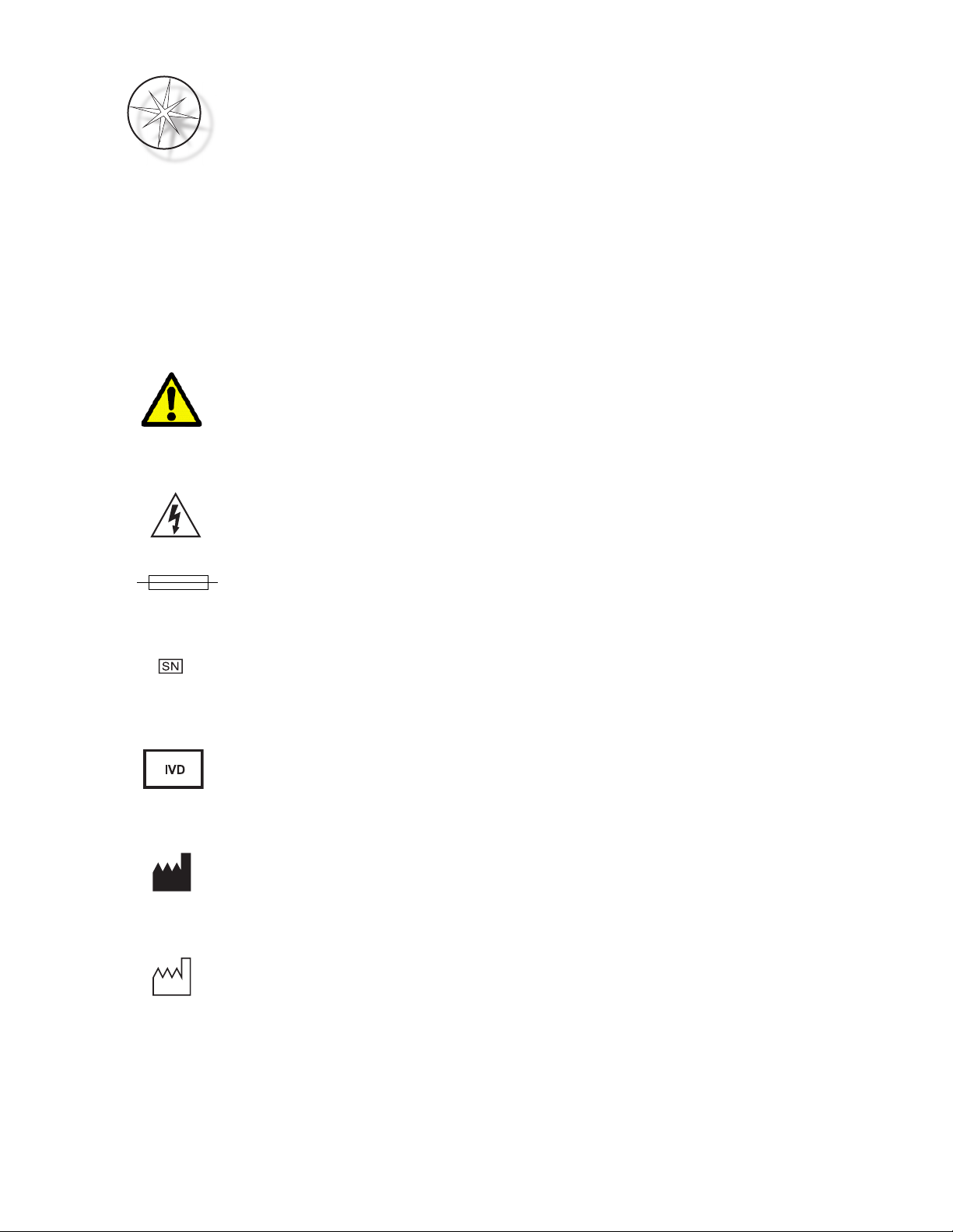
Symbol Title Description Standard Information
Caution
To indicate that caution is nec-
essary when operating the
device or control close to where
the symbol is placed, or to indi-
cate that the current situation
needs operator awareness or
operator action in order to avoid
undesirable consequences
ISO 7000 Graphical symbols for
use on equipment, symbol
0434B
Caution, risk of electric
shock
To identify equipment that has
risk of electric shock
IEC 60417 Graphical symbols
for use on equipment, symbol
5042
Fuse To identify fuse boxes or their
location.
IEC 60417 Graphical symbols
for use on equipment, symbol
5016
Serial number
Indicates the manufacturer’s
serial number so that a specific
medical device can be identi-
fied.
ISO 15223-1 Medical devices—
Symbols to be used with medi-
cal device labeling and informa-
tion to be supplied, Section
5.1.7
In vitro diagnostic medi-
cal device
Indicates a medical device that
is intended to used as an in vitro
diagnostic medical device
ISO 15223-1 Medical devices—
Symbols to be used with medi-
cal device labeling and informa-
tion to be supplied, Section
5.5.1
Manufacturer
Indicates the medical device
manufacturer, as defined in the
EU Directives 90/385/EEC, 93/
42/EEC and 98/79/EC
ISO 15223-1 Medical devices—
Symbols to be used with medi-
cal device labeling and informa-
tion to be supplied, Section
5.1.1
Date of manufacture
Indicates the date when the
medical device was manufac-
tured
ISO 15223-1 Medical devices—
Symbols to be used with medi-
cal device labeling and informa-
tion to be supplied, Section
5.1.3
Compass
™
Stainer Operator’s Manual page 9
Location of Labels on the Instrument
Figure 8-1 Rear of the Compass Stainer
Authorized Representa-
tive in the European Com-
munity
Indicates the Authorized Repre-
sentative in the European Com-
munity
ISO 15223-1 Medical devices—
Symbols to be used with medi-
cal device labeling and informa-
tion to be supplied, Section
5.1.2
Catalogue
Number
Indicates the manufacturer's
catalogue number so that the
medical device can be identified
ISO 15223-1 Medical devices—
Symbols to be used with medi-
cal device labeling and informa-
tion to be supplied, Section
5.1.6
“On” power
To indicate connection to the
mains, at least for mains
switches or their positions, and
all those cases where safety is
involved.
IEC 60417 Graphical symbols
for use on equipment, symbol
5007
“Off” power
To indicate disconnection from
the mains, at least for mains
switches or their positions, and
all those cases where safety is
involved
IEC 60417 Graphical symbols
for use on equipment, symbol
5008
Model/Rating Label Power/Fuse Label On/Off Switch
page 10 Compass
™
Stainer Operator’s Manual
Important Safety and Operational Information
•This instruction manual includes important information related to the operating safety and
maintenance of the system and it is an important part of the product.
•Obtain, review and retain the Safety Data Sheets (SDS) for the reagents used from the
manufacturers of the reagents. Follow the safety precautions and disposal recommendations
provided in SDS.
•Caution - flammable liquids. Keep away from fire, heat, sparks and flame. Be sure to close the
fume shield cover when instrument is in use.
•Caution - glass. This instrument processes microscope slides, which have sharp edges. Use
caution when handling glass slides.
•Caution - moving parts. Be sure to keep hands away from the transport arm mechanism
while the instrument is operating. Keep the fume shield doors closed while running the
instrument.
•As with all laboratory procedures, universal precautions should be followed.
Disposal
The system or the parts of the system must be disposed of according to prevailing local applicable
regulations.
Disposal of the Instrument
Disposal of Waste Electrical and Electronic Equipment (WEEE)
Hologic is dedicated to meeting country specific requirements associated with the environmentally
sound treatment of our products. Our objective is to reduce the waste arising from our electrical and
electronic equipment. Hologic realizes the benefits of subjecting such WEEE equipment to potential
reuse, treatment, recycling or recovery to minimize the amount of hazardous substances entering the
environment.
Your Responsibility
As a Hologic customer, you are responsible for ensuring that devices marked with the symbol shown
below are not placed into the municipal waste system unless authorized to do so by the authorities in
your area. Please contact Hologic (see below) prior to disposing of any electrical equipment provided
by Hologic.
Symbol Used on the Instrument
Do not dispose in municipal waste.
Contact Hologic (see below) for information regarding proper disposal.
Compass
™
Stainer Operator’s Manual page 11
Reclamation
Hologic will provide for the collection and proper reclamation of electrical devices we provide to
our customers. Hologic strives to reuse Hologic devices, subassemblies, and components
whenever possible. When reuse is not appropriate, Hologic will ensure the waste material is
properly disposed of.
Manufacturer/Corporate Headquarters Hologic, Inc.
250 Campus Drive
Marlborough, MA 01752 USA
Tel: 1-800-442-9892 1-508-263-2900
Fax: 1-508-229-2795
web:www.hologic.com
page 12 Compass
™
Stainer Operator’s Manual
INSTALLATION
WARNING:
Service installation only.
The Compass Stainer must be installed by personnel who have completed Hologic Service Training.
Action Upon Delivery
Inspect the packing cartons for damage. Report any damage immediately to the shipper and/or
Hologic Technical Support as soon as possible.
Leave the instrument in the packing cartons for Hologic Service installation.
Store the instrument in a suitable environment until installation (cool, dry, vibration-free area).
Retain all packaging material for the duration of the warranty period.
Preparation Prior to Installation
A pre-installation site assessment is performed by Hologic Service Personnel. Be sure to have
prepared any and all site configuration requirements as instructed by Service personnel.
Location
Locate the Compass Stainer near (within 3 meters) a 3-wire grounded power outlet that is free of
voltage fluctuations and power surges. If your system is configured with the optional UPS
(uninterruptable power supply), the UPS will be plugged into the electrical outlet and the stainer
plugged into the UPS.
Be sure the table or bench where the stainer is located can support a weight of 100 lbs (46 kg). The
system must be on a vibration-free surface.
The Instrument must be installed in an area in the laboratory that is well ventilated and free from
any ignition sources. The chemicals used in the Compass Stainer are flammable and noxious and
the system should not be operated in rooms with explosion hazards.
The instrument must not be located in direct sunlight or under a source of light that has a high
ultra violet light content.
If the laboratory’s bench depth is too shallow, the instrument may be allowed to overhang the table
by no more than 7 inches (18 cm). For stability, the rear 8 feet must be securely positioned on the
table.
Note:
Adequate clearance is necessary on the rear of the instrument.
Please review the section on hazards and safety before operating this unit (page 8.10).
Moving the Compass Stainer
CAUTION:
the system weighs approximately 55 lbs (25 kg) and should always be moved by at
least two people.
Compass
™
Stainer Operator’s Manual page 13
The Compass Stainer should be handled with care. Prior to relocating the stainer, unload any items
which may spill or break. Shut down the stainer. Disconnect power to the unit by removal of the
power cord from the electrical outlet or the UPS, depending on your configuration.
If the stainer must be moved, it should be grasped and lifted by the bottom of the housing.
If the stainer is to be shipped to a new location, please contact Hologic Technical Support. (Refer to
Service Information, page 8.40.)
Storage and Handling Post Installation
The Compass Stainer may be stored where it is installed. Be sure to clean and maintain the stainer as
described in the Maintenance section of this manual, page 8.38.
Power on the Compass Stainer
WARNING:
Grounded Outlet, Moving Parts
The power switch to the stainer is located on the rear of the unit. Refer to Figure 8-3. Press the rocker
switch to the ON position. The interface will display software version and a message that the
mechanisms are initializing while the system starts up and then standby screen will appear when the
stainer is ready for use.
Note
: The Compass Stainer can be left ON or you can choose to power it down when not in use. For
shut down or extended shut down, see page 8.14.
The startup display shows the software versions of Master Controller software and IO Controller
Software. It also prompts the user to remove all sample slide racks from the system before the system
begins mechanism initialization.
When the user presses the ENTER key, the system assumes that there are no racks in the system and
that the user’s hand or fingers are not obstructing the path of the transport mechanism. While the
system initializes the transport mechanism, the transport mechanism can move across the UNLOAD
and LOAD stations. During normal operation of the system the transport arm never crosses from
UNLOAD to LOAD stations to avoid accidental obstruction by the user while loading or unloading a
sample rack.
COMPASS STAINER
HOST SW: 2.00
IOC SW: 0.85
REMOVE ALL RACKS
PRESS ENTER
COMPASS STAINER
ADD SLIDES AT
LOAD STATION,
THEN PRESS RUN.
Startup Display Standby Display
page 14 Compass
™
Stainer Operator’s Manual
Shutdown Procedure
Remove all racks, cover all baths, close the fume shield.
The Stainer can be left ON when not in use or it can be powered down.
To power down, press the On/Off switch on the rear of the stainer to OFF.
For
extended
shutdown or if the stainer is to be taken out of service, remove any items that may be
on board and close the fume shield. Press the On/Off switch on the rear of the stainer to OFF.
Completely remove power to the stainer by unplugging the power cord from the power source.
System overview
Major functional areas of the Compass Stainer are shown in the following figures.
Figure 8-2 Compass Stainer - Front View
Fume Shield
Transport Arm
Mechanism
Slide Rack
Reagent Container
Keypad
Display
Fume Shield
Compass
™
Stainer Operator’s Manual page 15
Figure 8-3 Compass Stainer - Rear View
Description of Various Functional Areas:
Display
The Compass Stainer uses a 20 character wide x 8 line alpha-numeric passive LCD display
for an operator interface. The user can adjust the contrast of the displayed information in the service
mode to obtain the clearest text, based on User’s viewing angle.
Fume Shield
The cover helps minimize the reagent fumes escaping to the ambient air. It also allows
the user to observe the progress of the processing.
The Transport Arm Mechanism
The transport arm mechanism provides two types of travel to the
slide rack – up/down (z-axis) and rotary. Up/down motion allows immersing, agitating and
Charcoal Filter
Drain Hose Connector
(optional)
Power Entry and
On/Off Switch
Fuse Module
USB Data Port
Fume Shield
page 16 Compass
™
Stainer Operator’s Manual
removing of the sample slide racks from a reagent station and the rotary motion transports the slide
rack from one station to another station.
USB Data Port
The operator can use one of the Utilities to upload the user programs to an optional
external flash drive. The USB Flash Drive must be inserted into the USB Port in the rear of the unit.
The Utility mode software also allows for downloading programs from the drive.
It should be noted that when programs are downloaded, all the programs in the system memory
are erased except for Program 1 (ThinPrep Imaging protocol) and only the programs in the USB
Flash Drive are loaded.
Keypad
The Compass Stainer uses a membrane-style keypad with 20 keys. For user convenience, the keys are
arranged in three functional groups. The first group is for numeric entry; it includes the number keys
(0 – 9), CLEAR and ENTER. The second group is for programming and running the specimen
processing protocols, and includes the RUN, PROG, REVIEW and STOP keys. The third group,
consisting of the UP and DOWN ARROW keys, UTIL and SVC, is used to set up and maintain the
system.
Figure 8-4 Compass Stainer Keypad
The keypad has the following Keys:
KEY FUNCTION
0-9: These keys are used to provide a numeric entry.
Compass
™
Stainer Operator’s Manual page 17
CLEAR: Use this key to delete a programmed step from a processing protocol. Press the
CLEAR key when requested to erase stored information (e.g. to delete Stored
Programs).
ENTER: Use this key to accept or confirm the Numeric Data entry just made.

Arrow Keys are used to scroll through selection menus, and to raise and lower
the transport mechanism.
RUN: Use this Key to initiate a RUN.
PROG (PROGRAM): Use this key to start entering processing steps for a new program.
UTIL (UTILITY): This key allows access to various Utility functions to set up the system as well
as to view the status of the last Run.
REVIEW: Use this key to review programs that have previously been created and to edit
programs that have previously been stored.
SVC (SERVICE): This key provides access to various functions for servicing and troubleshooting
the system. Access to the Service Mode Function is password protected and is
intended for Hologic Service Personnel use only.
STOP: This Key is used to either Pause or Stop a Run in progress or exit various
Operator Interaction Modes.
The user interactions with the system are divided into the following categories:
1. Program, Review and Edit processing protocols
2. Running programmed protocols
3. Utility Functions (System setup, Review Last Run, etc.)
4. Service Functions (Troubleshooting information)
The system powers up in the Standby Mode. During Standby mode the mechanisms are not moving.
From Standby mode, the user must press ENTER to initialize the system - the transport arm moves
clockwise through all positions, stopping at Station1.
page 18 Compass
™
Stainer Operator’s Manual
The user can start a slide staining run by pressing the RUN key or select the UTILITY mode by
pressing UTIL. Once in RUN mode, the user can add another rack without exiting the RUN mode or
can initiate a PAUSE or CANCEL the run. Once the run is completed for all the racks that are
running, the system will enter the Standby Mode.
Several examples of display and keypad interactions are described below to clarify some of the
conventions and the nomenclature used in the displayed messages. Please contact Technical Support
if you have any questions or need further assistance.

Other Hologic Laboratory Equipment manuals

Hologic ThinPrep 5000 User manual

Hologic

Hologic ThinPrep 5000 User manual

Hologic ThinPrep 5000 User manual

Hologic

Hologic ThinPrep 5000 User manual

Hologic Rapid fFN 10Q User manual

Hologic

Hologic Rapid fFN 10Q User manual

Hologic Panther System User manual

Hologic

Hologic Panther System User manual

Hologic thinprep 2000 User manual

Hologic

Hologic thinprep 2000 User manual

Hologic ThinPrep 5000 User manual

Hologic

Hologic ThinPrep 5000 User manual

Hologic thinprep 2000 User manual

Hologic

Hologic thinprep 2000 User manual

Popular Laboratory Equipment manuals by other brands

Bruker 700'54 Ascend user manual

Bruker

Bruker 700'54 Ascend user manual

Excillum MetalJet D2+ operating manual

Excillum

Excillum MetalJet D2+ operating manual

Kurabo QuickGene-810 Operation manual

Kurabo

Kurabo QuickGene-810 Operation manual

Showa Denko Shodex IC SI-90 4E Operation manual

Showa Denko

Showa Denko Shodex IC SI-90 4E Operation manual

Labnet S0200 instruction manual

Labnet

Labnet S0200 instruction manual

Ele 38-1000 operating instructions

Ele

Ele 38-1000 operating instructions

Glass Expansion D-Torch manual

Glass Expansion

Glass Expansion D-Torch manual

Peak Scientific Solaris 10 user manual

Peak Scientific

Peak Scientific Solaris 10 user manual

Diesse MINI-CUBE user manual

Diesse

Diesse MINI-CUBE user manual

Thermo Scientific 1371 Operating manual and parts list

Thermo Scientific

Thermo Scientific 1371 Operating manual and parts list

TAN Bead Smart LabAssist Series user manual

TAN Bead

TAN Bead Smart LabAssist Series user manual

ibidi 11920 instruction manual

ibidi

ibidi 11920 instruction manual

Appleton appMix instruction manual

Appleton

Appleton appMix instruction manual

BioLAB BCFL-203 Operation manual

BioLAB

BioLAB BCFL-203 Operation manual

Bungard Hellas-E Instructions for use

Bungard

Bungard Hellas-E Instructions for use

Thermo Scientific AI 3000 operating manual

Thermo Scientific

Thermo Scientific AI 3000 operating manual

Drucker Diagnostics Horizon 6 FA Service manual

Drucker Diagnostics

Drucker Diagnostics Horizon 6 FA Service manual

NUVE NF 1200 user manual

NUVE

NUVE NF 1200 user manual

manuals.online logo
manuals.online logoBrands
  • About & Mission
  • Contact us
  • Privacy Policy
  • Terms and Conditions

Copyright 2025 Manuals.Online. All Rights Reserved.