manuals.online logo
Brands
  1. Home
  2. •
  3. Brands
  4. •
  5. Homefibre
  6. •
  7. Switch
  8. •
  9. Homefibre OMS 105 User manual

Homefibre OMS 105 User manual

POF Fast Ethernet Media Switch
OMS 105-150
Bedienungsanleitung / User’s Manual
Beschreibung
Der OMS105-150 ist ein Ethernet Switch mit fünf OPTOLOCK™
Kunststofflichtwellenleiter (POF) Anschlüssen. Er arbeitet normalerweise als
Layer 2 Switch mit 50m Datenübertragungslänge mittels POF für ein optisches
Heimnetzwerk. Die IEEE802.3 und IEEE802.3u Standards werden erfüllt. Die
Datenübertragung erfolgt über switching und store-and-foreward
Technologie, basierend auf einem IK MAC adress table. Die switching
Funktionen werden automatisch aufgerufen wenn die Quell- und Zieladressen
klar festgelegt sind. Der OMS105-150 hat 1.5 mm OPTOLOCK™ Anschlüsse und
ist RoHS konform.
Description
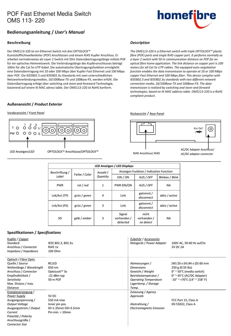
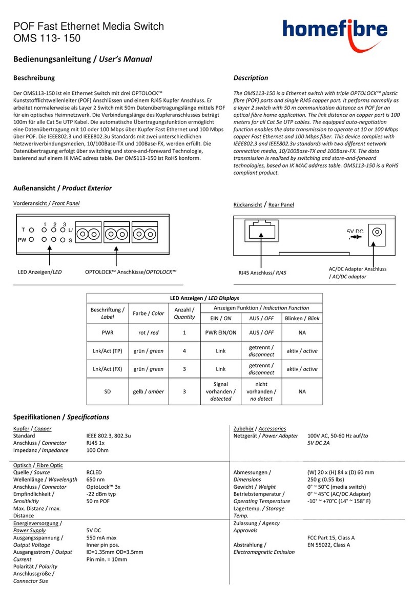
The OMS105-150 is a Ethernet switch with quintuple OPTOLOCK™ plastic fibre
(POF) ports. It performs normally as a layer 2 switch with 50 m communication
distance on POF for an optical fibre home application. This device complies
with IEEE802.3 and IEEE802.3u standards. The data transmission is realized by
switching and store-and-forward technologies, based on IK MAC address table.
Switching functions will be automatically invoked when source and destination
addresses are clearly specified. OMS105-150 is with 1.5 mm OPTOLOCK™
connector and is a RoHS compliant product.
Außenansicht / Product Exterior
Vorderansicht / Front Panel
Rückansicht / Rear Panel
LED Anzeigen / LED Displays
Beschriftung /
Label
Farbe /
Color
Anzahl /
Quantity
Anzeigen Funktion / Indication Function
EIN / ON
AUS / OFF
Blinken / Blink
PWR
rot / red
1
PWR EIN/ON
AUS / OFF
NA
Lnk/Act
grün / green
5
Link
getrennt / disconnect
aktiv / active
SD
gelb / amber
5
Signal vorhanden /
detected
nicht vorhanden / no detect
NA
Spezifikationen / Specifications
Standard
Standard
IEEE 802.3, 802.3u
Zubehör / Accessories
Netzgerät / Power Adapter
100V AC, 50-60 Hz auf/to
5V DC 2A
Optisch / Fibre Optic
Quelle / Source
Wellenlänge / Wavelength
Anschluss / Connector
Empfindlichkeit / Sensitivitiy
Max. Distanz / max. Distance
RCLED
650 nm
1.5 mm OptoLock™ 5x
-22 dBm typ
50 m on POF
Abmessungen / Dimensions
Gewicht / Weight
Betriebstemperatur / Operating
Temperature
Lagertemp. / Storage Temp.
(W) 120 x (H) 20 x (D) 80 mm
250 g (0.55 lbs)
0° ~ 50°C (media switch)
0° ~ 45°C (AC/DC Adapter)
-10° ~ +70°C (14° ~ 158° F)
Energieversorgung / Power Supply
Ausgangsspannung / Output Voltage
Ausgangsstrom / Output Current
Polarität / Polarity
Anschlussgröße / Connector Size
5V DC
550 mA max
Inner pin pos.
ID=1.35mm OD=3.5mm
Pin min. = 10mm
Zulassung / Agency Approvals
Abstrahlung / Electromagnetic
Emission
FCC Part 15, Class A
EN 55022, Class A
LED Anzeigen/LED Indicators
OPTOLOCK™ Anschlüsse/OPTOLOCK™ Connectors
3
2
1
5
4
U:L/A
L:SD
AC/DC Adapter Anschluss / AC/DC adaptor connector
PWR
5V DC IN
+
-
Power LED
Verbindungsdiagramm /
Connection Diagram
Stromversorgung
Der Media Switch ist automatisch eingeschaltet sobald der AC/DC Adapter mit
einer AC Steckdose verbunden ist. Ist der Media Switch korrekt an die
Stromversorgung angeschlossen leuchtet die „PWR“LED rot.
Power
The power of the media switch is automatically ON when the AC/DC adaptor is
connected to the AC power. The”PWR”LED (red) indicates the status of the
power.
Installation
Umgebung
Betreiben Sie den Media Switch in kühler, trockener Umgebung um
eine optimale Funktion zu gewährleisten.
Betreiben Sie den Media Switch in einem gut belüfteten Raum.
Lassen Sie allseitig genug Platz zur Belüftung des Media Switch.
Verbindung
1. Schließen Sie den Media Switch über den AC/DC Adapter an das
Stromnetz an.
2. Schneiden Sie die POF Kabel mit einem scharfen Messer um eine
flache, vertikale Oberfläche an den Kabelenden zu erhalten.
Vergewissern Sie sich, dass das POF Kabel den richtigen
Durchmesser hat.
3. Verbinden Sie die POF Medien Konverter oder Geräte mit POF
Kabeln mit dem Media Switch. Vergewissern Sie sich, dass die T
Seite des OPTOLOCK™ Anschlusses mit der R Seite des Gerätes
verbunden ist, und umgekehrt. Hat das eingehende optische Signal
einen ausreichenden Pegel leuchtet die „SD“ LED.
4. Sind die Verbindungen hergestellt leuchten die „Lnk/Act“ LEDs.
Installation
Place
Place the media switch at a cool dry place to make a good working
condition.
Place the media switch in an airy chamber. Leave enough space to
vents on each side of the media switch.
Connection
1. Power the media switch by using the AC/DC adaptor.
2. Cut the plastic optical fiber by a sharp knife to make a flat and
vertical surface on the fiber end. Make sure the diameter of the POF
is correct.
3. Connect the POF media converters or devices with the media switch
through plastic optical fibres. Note that terminal T of the
OPTOLOCK™ connector on the media switch should connect to
terminal R on the device and vice versa. The LED “SD” will turn ON
when the incoming optical signal is at a right level.
4. If links are good, the LEDs “Lnk/Act” will be ON.
Lieferumfang
1 OMS105-150 Media Switch
1 AC/DC Netzgerät
1 Netzkabel
1 Bedienungsanleitung
Package
1 OMS105-150 Media Switch
1 AC/DC Adaptor
1 power extension cord
1 User’s Manual
Richtlinie 2002/96/CE zur Behandlung, Sammlung, Wiederverwertung
und Entsorgung von Elektro- und Elektronikgeräten und deren
Bestandteile (waste electrical and electronic equipment –WEEE).
Das durchkreuzte Symbol eines Müllcontainers weist
darauf hin, dass das Gerät nicht im Hausmüll entsorgt
werden darf, sondern in dafür ausgerüsteten
Sammelzentren zur sachgemäßen Wiederverwendung
bzw. Entsorgung abzugeben ist.
Guideline 2002/96/CE concerning the handling, collection, recycling
and disposal for electrical and elelctronic equipment and their
components („waste electrical and electronic equipment“, known as
WEEE).
The crossed symbol on a rubbish container indicates
that the machine or device is not allowed to be disposed
of but it must be handed over to a suitably equipped
collection centre for proper recycling or disposal.
T R
OPTOLOCK™Anschluss/
OPTOLOCK™Connector
Media Switch
POF MK/Gerät
MC/Device
POF MK/Gerät
MC/Device
POF MK/Gerät
MC/Device
Rückseite / Rear
Vorderseite / Front
POF MK/Gerät
MC/Device
POF MK/Gerät
MC/Device
Änderungen und Druckfehler vorbehalten. Errors and omissions excepted. © Homefibre digital network gmbH 2009 OMS105-150_Manual_de-en_2009-10-22
homefibre digital network gmbh
Fratresstrasse 20
9800 Spittal a.d. Drau / Austria
www.homefibre.at
welcome@homefibre.at
Vertriebspartner/
Distribution Partner:

This manual suits for next models

1

Other Homefibre Switch manuals

Homefibre OMS 126S-150 User manual

Homefibre

Homefibre OMS 126S-150 User manual

Homefibre OMS 113- 150 User manual

Homefibre

Homefibre OMS 113- 150 User manual

Homefibre OMS 126 RR-DL User manual

Homefibre

Homefibre OMS 126 RR-DL User manual

Homefibre OMS 1412 RS-GIG User manual

Homefibre

Homefibre OMS 1412 RS-GIG User manual

Homefibre OMS 1034 FUS-GIG User manual

Homefibre

Homefibre OMS 1034 FUS-GIG User manual

Homefibre OMS 113- 220 User manual

Homefibre

Homefibre OMS 113- 220 User manual

Homefibre OMS 1412 RS-GIG+ User manual

Homefibre

Homefibre OMS 1412 RS-GIG+ User manual

Homefibre OMS 113-150 User manual

Homefibre

Homefibre OMS 113-150 User manual

Homefibre OMS 105 User manual

Homefibre

Homefibre OMS 105 User manual

Popular Switch manuals by other brands

SMC Networks SMC6224M Technical specifications

SMC Networks

SMC Networks SMC6224M Technical specifications

Aeotec ZWA003-S operating manual

Aeotec

Aeotec ZWA003-S operating manual

TRENDnet TK-209i Quick installation guide

TRENDnet

TRENDnet TK-209i Quick installation guide

Planet FGSW-2022VHP user manual

Planet

Planet FGSW-2022VHP user manual

Avocent AutoView 2000  AV2000BC AV2000BC Installer/user guide

Avocent

Avocent AutoView 2000 AV2000BC AV2000BC Installer/user guide

Moxa Technologies PT-7728 Series user manual

Moxa Technologies

Moxa Technologies PT-7728 Series user manual

Intos Electronic inLine 35392I operating instructions

Intos Electronic

Intos Electronic inLine 35392I operating instructions

Cisco Catalyst 3560-X-24T Technical specifications

Cisco

Cisco Catalyst 3560-X-24T Technical specifications

Asante IntraCore IC3648 Specifications

Asante

Asante IntraCore IC3648 Specifications

Siemens SIRIUS 3SE7310-1AE Series Original operating instructions

Siemens

Siemens SIRIUS 3SE7310-1AE Series Original operating instructions

Edge-Core DCS520 quick start guide

Edge-Core

Edge-Core DCS520 quick start guide

RGBLE S00203 user manual

RGBLE

RGBLE S00203 user manual

Thrustmaster FLIGHT SIMULATOR X quick guide

Thrustmaster

Thrustmaster FLIGHT SIMULATOR X quick guide

Southwire SURGE GUARD 41390 RVC troubleshooting guide

Southwire

Southwire SURGE GUARD 41390 RVC troubleshooting guide

Buhler Nivotemp NT 61 Brief instructions

Buhler

Buhler Nivotemp NT 61 Brief instructions

Kramer VS-41HDCP user manual

Kramer

Kramer VS-41HDCP user manual

Techly IDATA AU-270 user manual

Techly

Techly IDATA AU-270 user manual

Belkin F1U109 user manual

Belkin

Belkin F1U109 user manual

manuals.online logo
manuals.online logoBrands
  • About & Mission
  • Contact us
  • Privacy Policy
  • Terms and Conditions

Copyright 2025 Manuals.Online. All Rights Reserved.