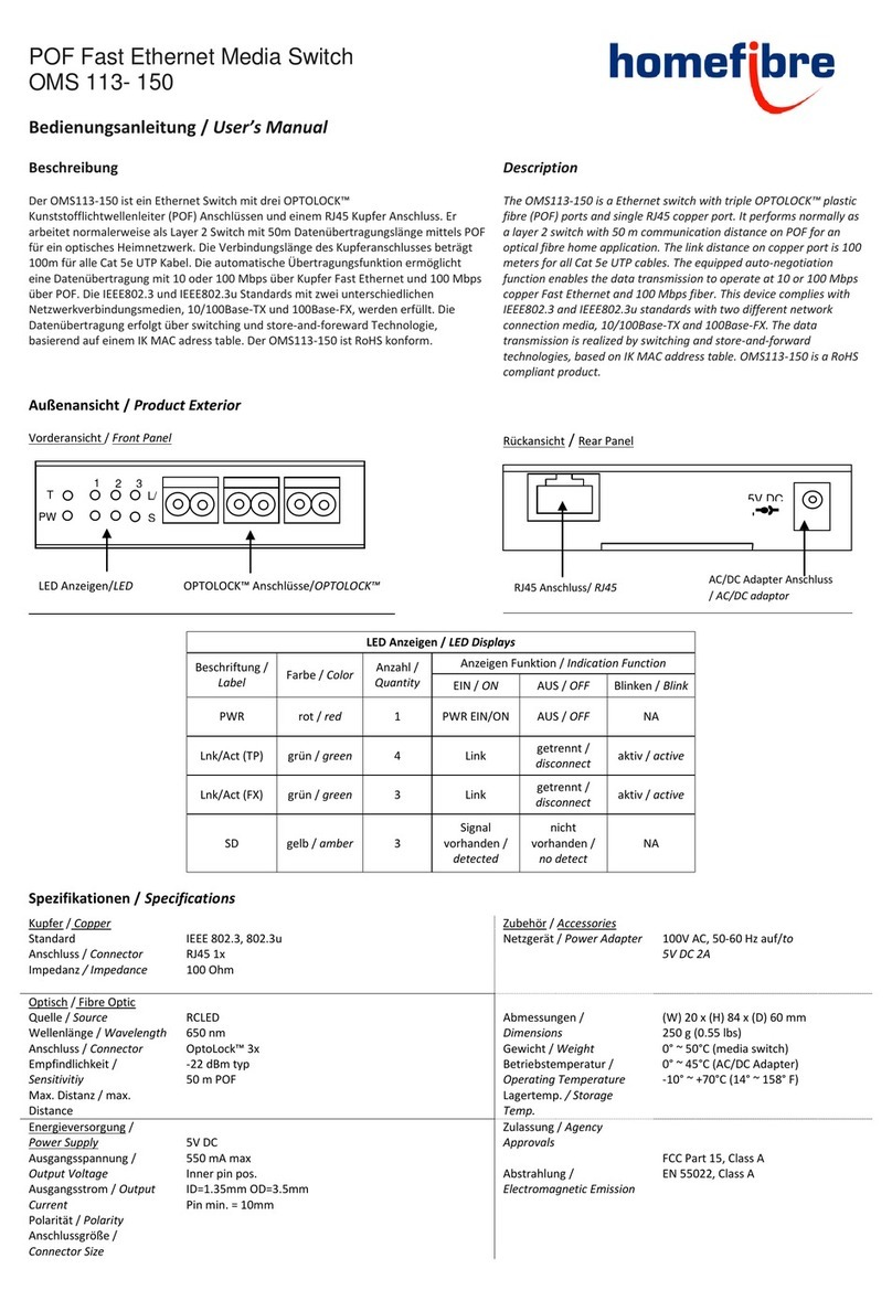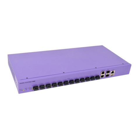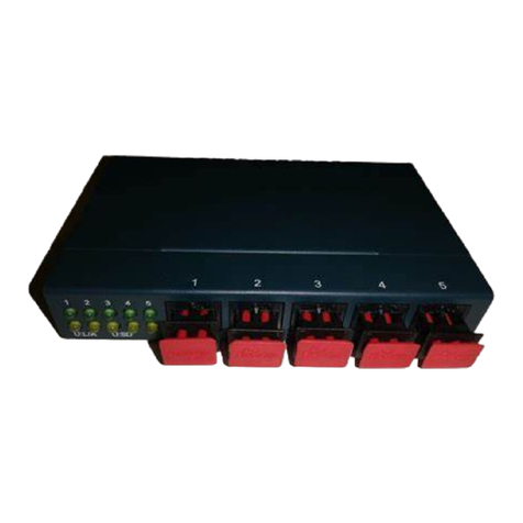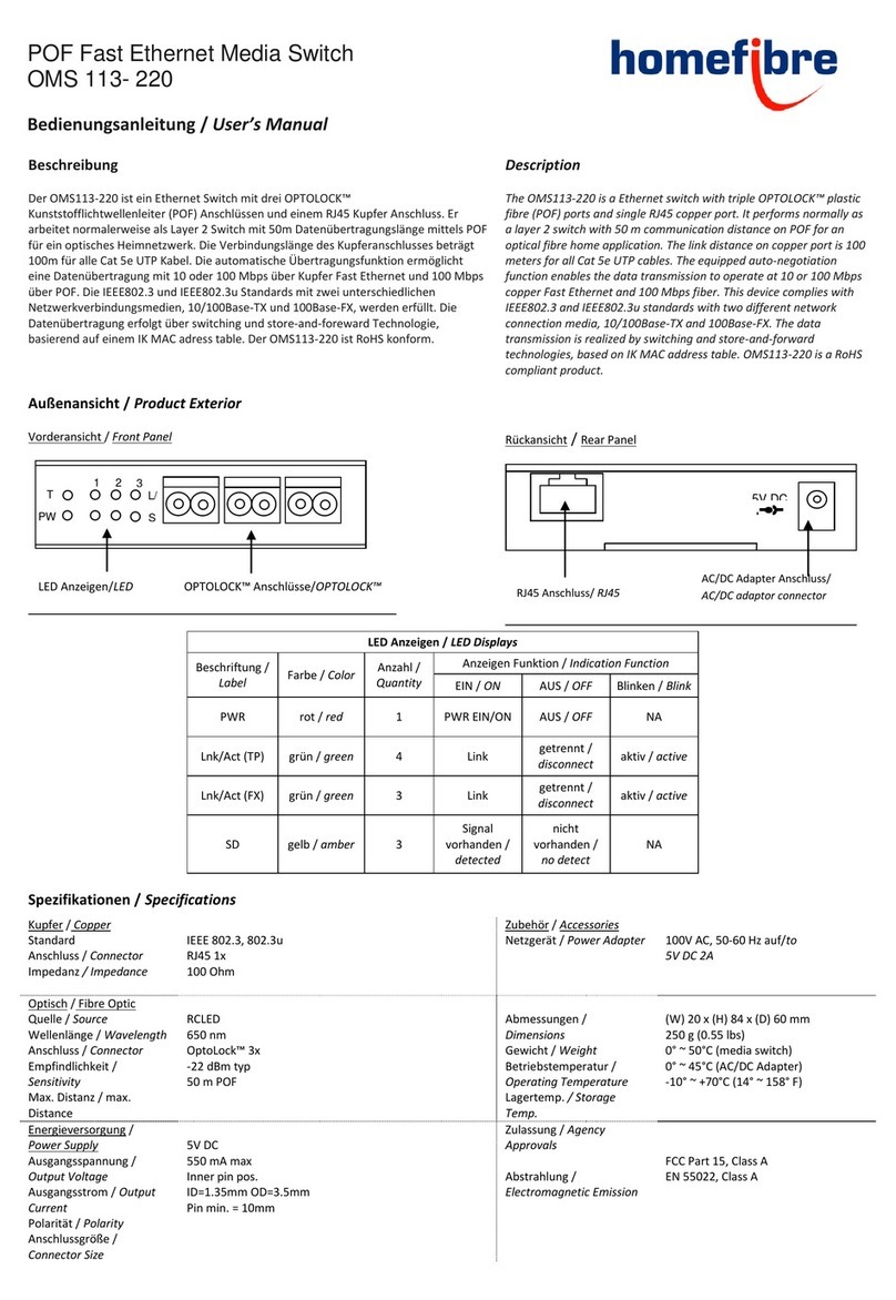
Verbindungsdiagramm /
Connection Diagram
Stromversorgung
Der Media Switch ist automatisch eingeschaltet sobald der AC/DC Adapter mit einer
AC Steckdose verbunden ist. Ist der Media Switch korrekt an die Stromversorgung
angeschlossen, leuchtet die PWR LED rot.
Power
The power of the media switch is automatically ON when the AC/DC
adaptor is connected to the AC power. The PWR LED (red) indicates
the status of the power.
Installation
Umgebung
•Betreiben Sie den Media Switch in kühler, trockener Umgebung um eine
optimale Funktion zu gewährleisten.
•Betreiben Sie den Media Switch in einem gut belüfteten Raum. Lassen Sie
allseitig genug Platz zur Belüftung des Media Switch.
Verbindung
1. Schließen Sie den Media Switch über den AC/DC Adapter an das Stromnetz
an.
2. Verbinden Sie 10Base-T oder 100Base-TX Geräte mittels UTP Kabel mit
dem Media Switch. Der RJ45 Anschluss hat eine AUTO MDI/MDI-X
Funktion.
3. Schneiden Sie die POF Kabel mit dem POF-Unicut (falls dieser nicht zur
Hand sein sollte, können Sie auch ein scharfes Messer verwenden) um eine
flache, vertikale Oberfläche an den Kabelenden zu erhalten.
4. Verbinden Sie die POF Medien Konverter oder Geräte mit POF Kabeln mit
dem Media Switch. Vergewissern Sie sich, dass die T Seite des
OPTOLOCK™ Anschlusses mit der R Seite des Gerätes verbunden ist, und
umgekehrt.
5. Sind die Verbindungen hergestellt leuchten die „Link/Act“ LEDs.
Installation
Environment
•Place the media switch at a cool dry place to make a good
working condition.
•Place the media switch in an airy chamber. Leave enough
space to vents on each side of the media switch.
Connection
1. Power the media switch by using the AC/DC adaptor.
2. Connect 10Base-T or 100Base-TX Ethernet devices to the
media switch by using UTP cable. The RJ45 connector
here is AUTO MDI/MDI-X function.
3. Cut the plastic optical fiber with the POF-Unicut (if not at
hand you can also use a sharp knife) to make a flat and
vertical surface on the fiber end.
4. Connect the POF media converters or devices with the
media switch through plastic optical fibres. Note that
terminal T of the OPTOLOCK™ connector on the media
switch should connect to terminal R on the device and vice
versa.
5. If links are established, the LEDs “Link/Act” will be ON.
Lieferumfang
•1 OMS113-150 bzw. 220 Media Switch
•1 AC/DC Netzgerät
•1 Netzkabel
•1 Bedienungsanleitung
Scope of delivery
•1 OMS113-150 or 220 Media Switch
•1 AC/DC Adaptor
•1 power extension cord
•1 User Manual
Richtlinie 2002/96/CE zur Behandlung, Sammlung, Wiederverwertung und
Entsorgung von Elektro- und Elektronikgeräten und deren Bestandteile
(„waste electrical and electronic equipment – WEEE“).
Das durchkreuzte Symbol eines Müllcontainers weist darauf hin, dass das
Gerät nicht im Hausmüll entsorgt werden darf, sondern in dafür ausgerüsteten
Sammelzentren zur sachgemäßen Wiederverwendung bzw. Entsorgung abzugeben ist.
Guideline 2002/96/CE concerning the handling, collection, recycling
and disposal for electrical and electronic equipment and their
components („waste electrical and electronic equipment“, known as
WEEE).
The crossed symbol on a rubbish container indicates
that the machine or device is not allowed to be
disposed of but it must be handed over to a suitably
equipped collection centre for proper recycling or
disposal.
T R
™
OPTOLOCK™Connector
POF
MK/Gerät
MC/Device
POF
MK/Gerät
MC/Device
PC/HUB
Rückseite/
Rear
Vorderseite/
Front
POF
MK/Gerät
MC/Device
homefibre digital network gmbh
Fratresstrasse 20
9800 Spittal a.d. Drau / Austria
www.homefibre.at
welcome@homefibre.at
Vertriebspartner/
Distribution artner:
Änderungen und Druckfehler vorbehalten.
Errors and omissions excepted.
© Homefibre Digital Network GmbH


